Joysway 8803V2 User manual
- Category
- Remote controlled toys
- Type
- User manual
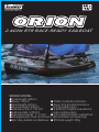
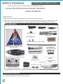
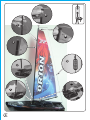
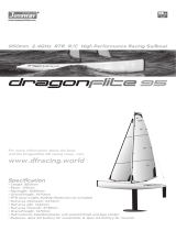
Joysway 8803V2 is a 2.4GHz RTR race-ready sailboat with a total length of 465mm and a beam of 150mm. It features a plastic molded boat stand, a 637mm fiberglass pipe mast and booms, a 37g standard sail servo and a 9g rudder servo, and a 2.4GHz 2CH digital proportional radio control system. With a sail area of 11.17 dm², the boat has a hull material that is plastic molded and a zinc alloy ballast. The RTR total weight is 950g. The boat is easy to assemble and operate, making it suitable for both beginners and experienced sailors.
Joysway 8803V2 is a 2.4GHz RTR race-ready sailboat with a total length of 465mm and a beam of 150mm. It features a plastic molded boat stand, a 637mm fiberglass pipe mast and booms, a 37g standard sail servo and a 9g rudder servo, and a 2.4GHz 2CH digital proportional radio control system. With a sail area of 11.17 dm², the boat has a hull material that is plastic molded and a zinc alloy ballast. The RTR total weight is 950g. The boat is easy to assemble and operate, making it suitable for both beginners and experienced sailors.


-
 1
1
-
 2
2
-
 3
3
-
 4
4
-
 5
5
-
 6
6
-
 7
7
-
 8
8
-
 9
9
-
 10
10
-
 11
11
-
 12
12


Joysway 8803V2 User manual
- Category
- Remote controlled toys
- Type
- User manual
Joysway 8803V2 is a 2.4GHz RTR race-ready sailboat with a total length of 465mm and a beam of 150mm. It features a plastic molded boat stand, a 637mm fiberglass pipe mast and booms, a 37g standard sail servo and a 9g rudder servo, and a 2.4GHz 2CH digital proportional radio control system. With a sail area of 11.17 dm², the boat has a hull material that is plastic molded and a zinc alloy ballast. The RTR total weight is 950g. The boat is easy to assemble and operate, making it suitable for both beginners and experienced sailors.
Ask a question and I''ll find the answer in the document
Finding information in a document is now easier with AI
Related papers


Other documents
-
 DRAGONFLITE 95 8811 User manual
-
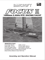 Bancroft Focus II 1000mm 2.4GHz RTR Racing Yacht User manual
-
Hobbico VELA ONEmeter Specification
-
 Catalina Capri 22 Owner's manual
-
AquaCraft Paradise AquaCraft User manual
-
 RS SAILING Vision Rigging Manual
-
Laser SB3 Rigging Manual
-
Hobie Open 5.00 Assembly Manual
-
-


