
Page|1
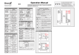
1496 & 1498
1/16 & 1/8 DIN Industrial Controller
User Manual

Page|2
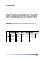
DYNISCO 1496/1498 Temperature Controller QUICK START CARD
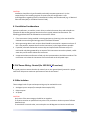
This guide is intended to provide basic information on setting up the Dynisco 1496/1498 controller. Other
configurations are possible. See the main part of 1496/1498 manual for additional parameters and options.
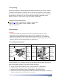
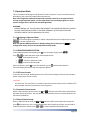
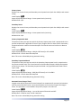
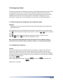
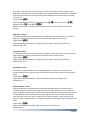
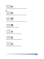
1. Wring
Dynisco 1496 Dynisco 1498
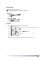
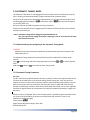
2. Configuration
From the main operator screen:
Enter Select mode by holding and pressing
Press until upper display reads ConF
Press , ULoc is displayed
Press to change ULoc code to then press . Func is displayed
Press or to select required function then press to save
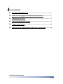
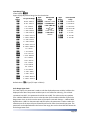
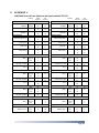
Press , Inpt is displayed. Use or to select sensor type from table below then press to save.
Press until PLA1 is displayed. Use or to adjust low alarm setpoint then press to save
Press until bAL2 is displayed. Use or to set band alarm setpoint then press to save
Hold and press to return to Select mode
Press until OPtr is displayed, then press to return to Operator Mode
For the alarms to align with the LEDs and labeling on the front of the controller Alarm 1 Type and Alarm 2 Type
should be left at their default settings. Other parameters in the configuration mode can be left at the default settings.
Code
Input Type
Code
Input Type
Code
Input Type
Code
Input Type
Code
Input Type
bC
TC B °C
KC
TC K °C
NC
TC N °C
P24C
PtRh 20%/40% °c
)_20
0-20 mA DC
bF
TC B °F
KF
TC K °F
nF
TC N °F
P24F
PtRh 20%/40% °F
4_20
4-20 mA DC
CC
TC C °C
K.C
TC K °C 0.1
rC
TC R °C
ptC
RTD °C
)_50
0-50 mV DC
CF
TC C °F
K.F
TC K °F 0.1
rF
TC R °F
ptF
RTD °F
10.50
10-50 mV DC
JC
TC J °C
LC
TC L °C
SC
TC S °C
Pt.C
RTD °C 0.1
)_5
0-5 V DC
JF
TC J °F
LF
TC L °F
SF
TC S °F
Pt.f
RTD °F 0.1
1_5
1-5 V DC
J.C
TC J °C 0.1
L.C
TC L °C 0.1
TC
TC T °C
)_10
0-10 V DC
J.F
TC J °F 0.1
L.F
TC L °F 0.1
tF
TC T °F
2_10
2-10 V DC
HEAt
Heat Only
CooL
Heat/Cool
Indc
Indicator Only

Page|3
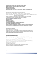
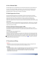
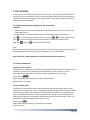
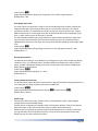
3. Operation Mode
There are 3 modes of operation in the controller.
Off – No temperature control in this mode. Temperature is still displayed
Auto – Normal temperature control mode
MAN – Manually adjust output power level
To change mode:
Press , lower display will read Cntr
Press or to select required mode
Press
To adjust Setpoint in Auto Mode
Press , Lower display will read SP
Press or to set required value.
Press to return to normal display
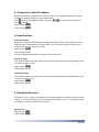
4. Auto Tune
To perform an Auto-Tune, the machine needs to be at ambient temperature.
Press to go to setpoint display.
Adjust setpoint to normal operating temperature (must be at least 15°C/29°F higher than process value)
Hold and press to enter Select Mode
Press until upper display reads Atun
press , ULoc is displayed
Press to change ULoc code to 44 then press . Ptun is displayed
Press to change Ptun to On.
Hold and press to return to Select Mode
Press until OPtr is displayed
Press to return to Operator Mode
AT light will flash while Pre-Tune is running. Once the Pre-Tune is complete, the AT light will go off.

Page|4
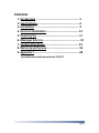
Contents
1. Introduction …………………………………………………….. 5
2. Specifications……………………………………………………. 6
3. Installation……………………………………………………….. 9
4. Electrical Installation………………………………………… 13
5. Powering Up…………………………………………………….. 17
6. Messages & Errors……………………………………………… 19
7. Configuration & Use…………………………………………. 22
8. Warranty and Service……………………………………….. 46
9. Appendix 1 ………………………………………………………..48
Cross Reference with Dynisco Model TCS/TCE

Page|5
1 INTRODUCTION
The 1496, 1498 temperature controller is an economic solution to precision temperature
control of extruders. With two DIN sizes and multiple output configurations, the controller
is suitable for twin and single screw extruders, both heat only die and adapter zones, in
addition to heat cool for barrel zones. 1496, 1498 can also be used in an indicator-only
mode, allowing one instrument to be used for all applications. With three default
parameter sets for Indicator, Heat and Heat/Cool modes, the 1496, 1498 controller offers
the ultimate in flexibility for the control of industrial plastic extruders. 1496, 1498 was
designed for fast configuration to match specific settings and default parameters of the
extruder. Two alarm settings are possible for process high, process low, SP deviation,
band, logical OR / AND, loop alarm for process control security. Process alarms have
adjustable hysteresis.
WARNING NOTE: The user should be aware that if this equipment is used in a manner not
consistent with the specifications and instructions in this manual, the protection provided by the
equipment might be impaired.
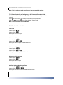
Product Codes (ordering options)
149
Configuration
Option 1
Option 2
Option 3
Option A
Power
Supply
6
1/16 DIN
Temperature
Controller
0
Not Fitted
0
Not Fitted
0
Not Fitted
0
Not Fitted
0
100-
240VAC
1
Relay
1
Relay
1
Relay
1
RS485
2
24-48VAC
or DC
8
1/8 DIN
Temperature
Controller
2
DC drive
for SSR
2
DC drive
for SSR
2
DC drive
for SSR
8
Triac
8
Triac

Page|6
2 SPECIFICATIONS
2.1 Mechanical Specifications……………………………………………………….. 7
2.2 Main Power Supply & Environmental Specification………………… 7
2.3 Display Specification……………………………………………………………….. 7
2.4 Universal Input Specification…………………………………………………… 7
2.5 Output Specification………………………………………………………………….8
2.6 Optional Serial Communication Interface Specification…………….8
2.1 Mechanical Specification

Page|7
Front Panel Size: 1/16 DIN = 48 x 48mm; 1/8 DIN = 96 x 48mm,
Depth Behind Panel: 1/16 DIN = 110mm; 1/8 DIN = 100mm.
Weight: 0.21kg maximum.
Installation: Panel mounting.
Rear Terminal Block: 1/16 DIN = 16 screw terminals; 1/8 DIN = 23 screw terminals.
2.2 Main Power Supply & Environmental Specification
Main Power Supply: 100 to 240VAC, 50/60Hz switching. Option: 24VAC/DC.
Power supply variation: From -15% to +10% (for 100 to 240Vac). From 22 to 65Vdc or from 20 to
48Vac (for optional 24Vac/dc).
Power Consumption: 7.5VA for 100 to 240Vac; 7.5VA for 24Vac; 5W for 24Vdc.
Temperature: 0 °C to 55 °C (Operating), -20 °C to 80 °C (Storage)
Relative humidity: 20% to 95% non-condensing.
Altitude: <2000m
Standards: CE, UL, ULC
CE: Directive 2004/108/EC
EMI: Complies with EN61326 (Susceptibility & Emissions)
ISO: ISO 9001:2008 production environment
Safety consideration: Complies with EN61010-1, UL61010-1 & CSA 22.2 No 1010.192
Panel sealing: Front to IP66 when correctly mounted – refer to section 3 installing.
2.3 Display Specification
Display: LED technology, custom type.
Upper digits: Red color, 4 numeric digits, 7 segments with decimal point 10mm high.
Lower digits: Green color, 4 numeric digits, 7 segments with decimal point 8mm high.
Scaling: -1999 to 9999, with adjustable decimal point
2.4 Universal Input Specification
Thermocouple input types: J, K, C, R, S, T, B, L, N & PtRh20% vs. PtRh40%
Thermocouple calibration: 0.1% of full range, 1LSD (1°C for Thermocouple CJC).
BS4937, NBS125 & IEC584.
RTD 3 Wire input: PT100, 50Ω per lead maximum (balanced)
PT100 calibration: 0.1% of full range, 1LSD. BS1904 & DIN43760 (0.00385//°C).
Accuracy: ±0.1% of input range ±1 LSD (T/C CJC better than 1°C)
Sampling Rate: 4 per second.
Impedance: >10Mresistive.
Sensor Break Detection: Thermocouple, RTD. Control outputs turn off.
Isolation: Isolated from all outputs (except SSR driver).
Note:

Page|8
Universal input must not be connected to operator accessible circuits if relay outputs are
connected to a hazardous voltage source. Supplementary insulation or input grounding would
then be required.
2.5 Output Specification
Relay
Contact Type & Rating: Single pole double throw (SPDT); 2A resistive at 120/240VAC.
Lifetime: >500,000 operations at rated voltage/current.
Isolation: Basic Isolation from universal input and SSR outputs.
SSR Driver
Drive Capability: SSR drive voltage >10V into 500 min.
Isolation: Not isolated from universal input or other SSR driver outputs.
Triac
Operating Voltage: 20 to 280Vrms (47 to 63Hz).
Current Rating: 0.01 to 1A (full cycle rms on-state @ 25°C); derates linearly above 40°C to 0.5A
@ 80°C.
Isolation: Reinforced safety isolation from inputs and other outputs.
2.6 Optional Serial Communication Interface Specification
Serial interface: RS-485 type.
Baud rate: 1200, 2400, 4800, 9600 or 19200 bps.
Protocol type: Modbus/West ASCII
Isolation: Reinforced safety isolation from all inputs and outputs.

Page|9
3 INSTALLATION
3.1 Unpacking ………………………………………………………………………………….10
3.2 Dimensional Information…………………………………………………………..10
3.3 Installation ………………………………………………………………………………..10
3.3.1 Installing Option Modules……………………………………………………………….10
3.3.2 Option Module Connectors………………………………………………………………11
3.4 Panel-Mounting ………………………………………………………………………….11

Page|10
3.1 Unpacking
Remove the product from its packing. Retain the packing for future use, in case it is necessary
to transport the instrument to a different site or to return it to the supplier for repair/testing.
The instrument is supplied with a panel gasket and push-fit fixing strap. A quick start manual is
supplied with the instrument, in one or more languages. Examine the delivered items for
damage or defects. If any are found, contact your supplier immediately.
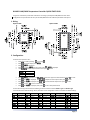
3.2 Dimensional Information
Dimensions: 1/16DIN = 48×48×120mm, 1/18DIN = 96×48×110mm
Depth behind panel: 1/16DIN = 110mm, 1/18DIN = 100mm
Wight: 0.21kg Maximum
3.3 Installation
CAUTION:
Installation should be only performed by technically competent personnel. It is the
responsibility of the installing engineer to ensure that the configuration is safe. Local
Regulations regarding electrical installation & safety must be observed - e.g. US National
Electrical Code (NEC) or Canadian Electrical Code. Impairment of protection will occur if the
product is used in a manner not specified by the manufacturer.
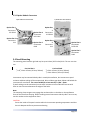
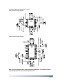
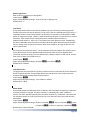
3.3.1 Installing Option Modules
1/16 DIN Size Instruments
1/8 DIN Size Instruments
CPU PCB
Option
Module 1
Option
Module2
Mounting
Struts
Option
Module A
Option
Module 3
PSU PCB
CPU PCB
Option
Module2
Option
Module1
Mounting
Struts
Option
Module A
Option
Module 3
PSU PCB
To access modules 1 or A, first detach the PSU and CPU boards from the front by lifting first the
upper, and then lower mounting struts. Gently separate the boards.
a. Plug the required option modules into the correct connectors, as shown below.
b. Locate the module tongues in the corresponding slot on the opposite board.
c. Hold the main boards together while relocating back on the mounting struts.
d. Replace the instrument by aligning the CPU and PSU boards with their guides in the housing,
and then slowly push the instrument back into position.

Page|11
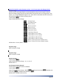
3.3.2 Option Module Connectors
1/16 DIN Size Instruments
1/8 DIN Size Instruments
Option Slot 1
Connectors
PL7 & PL8
Option Slot 2
Connectors
PL4
Option Slot A
Connectors
PL5 & PL6
Option Slot 3
Connectors
PL4B
Option Slot
1
Connectors
PL7 & PL8
Option Slot
2
Connectors
PL4
Option Slot A
Connectors
PL5 & PL6
Option Slot 3
Connectors
PL4B
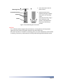
3.4 Panel-Mounting
The mounting panel must be rigid and may be up to 6.0mm (0.25 inches) thick. The cut-out sizes
are:
Cut-Out Dim A
Cut-Out Dim B
1/16 & 1/8 DIN = 45mm (+0.5mm/-0.0mm)
1/16 DIN = 45mm (+0.5mm/-0.0mm)
1/8 DIN = 92mm (+0.5mm/-0.0mm)
Instruments may be mounted side-by-side in a multiple installation, but instrument to panel
moisture and dust sealing will be compromised. Allow a 20mm gap above, below and behind the
instrument for ventilation. The cut-out width (for n instruments) is: (48n – 4)mm.
If panel sealing must be maintained, mount each instrument into an individual cut-out with
6mm or more clearance between the edges of the holes.
Note:
The mounting clamp tongues may engage the ratchets either on the sides or the top/bottom
faces of the Instrument housing. When installing several Instruments side-by-side in one cut-out,
use the ratchets on the top/bottom faces.
CAUTION:
Ensure the inside of the panel remains within the instrument operating temperature and that
there is adequate airflow to prevent overheating.

Page|12
Mounting Panel
1. Insert instrument into the
panel cut-out.
Instrument Housing
2. Hold front bezel firmly
(without pressing on display
area), and re-fit mounting
clamp.
Push clamp forward, using a
tool if necessary, until
gasket is compressed and
instrument held firmly in
position.
Ratchets
Gasket
Figure 2 Panel-Mounting the instrument
CAUTION:
For an effective IP66 seal against dust and moisture, ensure gasket is well compressed
against the panel, with the 4 tongues located in the same ratchet slot.
Once the instrument is installed in its mounting panel, it may be subsequently removed from
its housing, if necessary, as described in the Fitting and Removing Option Modules section.

Page|13
4 ELECTRICAL INSTALLATION
4.1 Installation Considerations …………………………………………………………………14
4.2 AC Power Wiring - Neutral (for 100-264 V AC versions) ………………………14
4.3 Wire Isolation ……………………………………………………………………………………...14
4.4 Use of Shielded Cable …………………………………………………………………………...15
4.5 Noise Suppression at Source ………………………………………………………………...15
4.6 Sensor Placement (Thermocouple or RTD) ………………………………………….15
4.7 Connections and Wiring ……………………………………………………………………….15

Page|14
CAUTION:
Installation should be only performed by technically competent personnel. It is the
responsibility of the installing engineer to ensure that the configuration is safe.
Local Regulations regarding electrical installation & safety must be observed (e.g. US National
Electrical Code (NEC) or Canadian Electrical Code).
4.1 Installation Considerations
Ignition transformers, arc welders, motor drives, mechanical contact relays and solenoids are
examples of devices that generate electrical noise in typical industrial environments. The
following guidelines MUST be followed to minimize their effects.
1 If the instrument is being installed in existing equipment, the wiring in the area should be
checked to ensure that good wiring practices have been followed.
2 Noise-generating devices such as those listed should be mounted in a separate enclosure. If
this is not possible, separate them from the instrument, by the largest distance possible.
3 If possible, eliminate mechanical contact relays and replace with solid-state relays. If a
mechanical relay being powered by an output of this instrument cannot be replaced, a solid-
state relay can be used to isolate the instrument.
4 A separate isolation transformer to feed only the instrumentation should be considered. The
transformer can isolate the instrument from noise found on the AC power input.
4.2 AC Power Wiring - Neutral (for 100-264 V AC versions)
It is good practice to ensure that the AC neutral is at or near ground (earth) potential. A proper
neutral will help ensure maximum performance from the instrument.
4.3 Wire Isolation
Three voltage levels of input and output wiring may be used with the unit:
1 Analogue input or output (for example thermocouple, RTD)
2 Relays outputs
3 AC power
CAUTION:
Only wires of the same category should be run together.
If any wires need to run parallel with any other lines, maintain a minimum space of 150mm
between them.
If wires MUST cross each other, ensure they do so at 90 degrees to minimize interference.

Page|15
4.4 Use of Shielded Cable
All analog signals must use shielded cable. This will help eliminate electrical noise induction on
the wires. Connection lead length must be kept as short as possible while keeping the wires
protected by the shielding. The shield should be grounded at one end only. The preferred
grounding location is at the sensor, transmitter or transducer.
4.5 Noise Suppression at Source
Usually when good wiring practices are followed, no further noise protection is necessary.
Sometimes in severe electrical environments, the amount of noise is so great that it has to be
suppressed at the source. Many manufacturers of relays, contactors etc supply 'surge
suppressors' which mount on the noise source. For those devices that do not have surge
suppressors supplied, Resistance-Capacitance (RC) networks and/or Metal Oxide Varistors (MOV)
may be added.
Inductive coils:- MOVs are recommended for transient suppression in inductive coils, connected
in parallel and as close as possible to the coil. Additional protection may be provided by adding
an RC network across the MOV.
4.6 Sensor Placement (Thermocouple or RTD)
If the temperature probe is to be subjected to corrosive or abrasive conditions, it must be
protected by an appropriate thermo well. The probe must be positioned to reflect true process
temperature:
1. In a liquid media - the most agitated area
2. In air - the best circulated area
CAUTION: The placement of probes into pipe work some distance from the heating vessel leads
to transport delay, which results in poor control. For a two wire RTD, a wire link should be used
in place of the third wire (see the wiring section for details). Two wire RTDs should only be used
with lead lengths less than 9 feet (3 meters). Use of three wire RTD's is strongly recommended
to reduce errors do to lead resistance.
4.7 Connections and Wiring
CAUTION:
All external circuits connected must provide double insulation. Failure to comply with the
installation instructions may impact the protection provided by the unit.
WARNING:
TO AVOID ELECTRICAL SHOCK, AC POWER WIRING MUST NOT BE CONNECTED TO THE SOURCE
DISTRIBUTION PANEL UNTIL ALL WIRING PROCEDURES ARE COMPLETED. CHECK THE
INFORMATION LABEL ON THE CASE TO DETERMINE THE CORRECT VOLTAGE BEFORE
CONNECTING TO A LIVE SUPPLY.

Page|16
Use Copper Conductors (except for T/C Input):
1496 Controller wiring diagram:
1498 Controller wiring diagram:
Note: The wiring diagrams above shows all possible combinations. The actual connections
required depend on the exact model and options fitted.


Page|18
CAUTION:
Ensure safe wiring practices have been followed. When powering up for the first time,
disconnect the output connections.
The instrument must be powered from a supply according to the wiring label on the side of
the unit. The supply will be either 100 to 240V AC, or 24/48V AC/DC powered. Check carefully
the supply voltage and connections before applying power.
5.1 Powering Up Procedure
At power up, a self-test procedure is automatically started, during which the display and LED
indicators are all lit. At the first power up from new, the message “Go to Configuration mode”
(Goto
ConF) is displayed. Access to other menus is denied until configuration mode is completed. At
all other times, the instrument returns to Operation Mode once the self-test procedure is
complete.
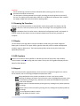
5.2 Display
The instrument has 4 digit 10mm red upper and 8mm inched (mm) green lower 8 segment
display plus 5 indicators. The upper display typically shows the process variable and adjustable
variables ranges or descriptions. The lower display typically shows the set point values and
adjustable parameters.
5.3 LED Functions
There are five red LED's that by default. It indicates the status of the primary and secondary
control outputs, automatic tuning and alarm status. The top line of the graphical display has four
labels for LED indicators.
5.4 Keypad
Each instrument has four keypad switches, which are used to navigate through the user menus,
set the manual, auto or off tunings and adjust the parameter values.
Moves backwards to the previous parameter or screen in the current mode.
CAUTION: If editing a parameter, ensure that the current (highlighted) parameter value
is saved before pressing the key; otherwise this action will not update the instrument
to the value displayed.
Editable values can be decreased by pressing this key. Holding the key down speeds up
the change.
Editable values can be increased by pressing this key. Holding the key down speeds up
the change.
Turn the Operation mode on and off.
Save and update parameter’s value.


Page|20
6.1 Parameters in Default Conditions
When the instrument is powered on for the first time or the hardware configuration has been
changed, the display will display “Go to configuration”.
Press to enter the configuration mode, next press or to enter the unlock code, then
press to proceed.
Upper Display: Conf
Lower Display: Goto
6.2 Input Problems
Input Sensor Break
Whenever a problem is detected with the process variable or auxiliary input connections, their
displayed value is replaced with the word “OPEN”. This may be the result of a failed sensor, a
broken connection or an input circuit fault.
Upper Display: OPEN
Lower Display: Normal
Correct the signal/wiring problem to continue normal operation.
Input Over Range
If the measured process variable value is more than 5% above than the Scale Range Upper Limit,
its value is replace by “[HH]”.
Upper Display: [HH]
Lower Display: Normal
Input Under Range
If the measured process variable value is more than 5% below than the Scale Range Lower Limit,
its value is replace by “[LL]”.
Upper Display: [LL]
Lower Display: Normal
6.3 Option Module Errors
The “Option n Error” display is shown when an error detected with the installed option modules
- where “n” is the slot number for the fault. Replace the module in slot “n”. If this does not solve
the problem, return the instrument for servicing.
Option 1 Error
Upper Display: Err
Lower Display: OPn1
Page is loading ...
Page is loading ...
Page is loading ...
Page is loading ...
Page is loading ...
Page is loading ...
Page is loading ...
Page is loading ...
Page is loading ...
Page is loading ...
Page is loading ...
Page is loading ...
Page is loading ...
Page is loading ...
Page is loading ...
Page is loading ...
Page is loading ...
Page is loading ...
Page is loading ...
Page is loading ...
Page is loading ...
Page is loading ...
Page is loading ...
Page is loading ...
Page is loading ...
Page is loading ...
Page is loading ...
Page is loading ...
Page is loading ...
-
 1
1
-
 2
2
-
 3
3
-
 4
4
-
 5
5
-
 6
6
-
 7
7
-
 8
8
-
 9
9
-
 10
10
-
 11
11
-
 12
12
-
 13
13
-
 14
14
-
 15
15
-
 16
16
-
 17
17
-
 18
18
-
 19
19
-
 20
20
-
 21
21
-
 22
22
-
 23
23
-
 24
24
-
 25
25
-
 26
26
-
 27
27
-
 28
28
-
 29
29
-
 30
30
-
 31
31
-
 32
32
-
 33
33
-
 34
34
-
 35
35
-
 36
36
-
 37
37
-
 38
38
-
 39
39
-
 40
40
-
 41
41
-
 42
42
-
 43
43
-
 44
44
-
 45
45
-
 46
46
-
 47
47
-
 48
48
-
 49
49


Dynisco 1496 User manual
- Type
- User manual
- This manual is also suitable for
Ask a question and I''ll find the answer in the document
Finding information in a document is now easier with AI
Related papers
-
Dynisco UPR900 Process Indicator User manual
-
-
-
-
-
-
-
-
-
Other documents
-
 West Control Solutions 4170+ User manual
-
 PPI OmniX Single Set Point Temperature Controller User manual
-
MULTISPAN TC-49 Owner's manual
-
-
-
PPI AIMS-4-8X User manual
-
Chromalox 4040 Operating instructions
-
-
-

