Acewell ACE-2956 series User manual
- Category
- Bicycle accessories
- Type
- User manual

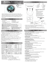
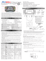
Thank for purchasing an Acewell ATV/Motorcycle/Scooter computer. This
manual is specially designed for the ACE-2956xx series. Each model has 4-6
LED indicators. Different models have different LED indicators; a fuel meter is
optional, but all other functions are the same. You may find that the photo above
has a set of LED indicators different from your computer; the photo is for
reference only.
ATV Computer
FEATURES
SPECIFICATIONS
Power Input: 12VDC.
Speed Sensor: No Contact Magnetic Sensor.
Tachometer Input: CDI or Ignition-coil signal.
Wheel Circumference Setting: 1mm - 3999 mm (1 mm increment)
Operation Temperature: -10°C - +80°C (inner housing)
Storage Temperature: -25°C - +85°C (inner housing)
FUNCTIONS
www.acewell-meter.com
Includes analog and digital tachometer, speedometer
(300km/h), trip meter, odometer, clock, average
speedometer, maximum speedometer, riding timer and
cumulative riding timer.
Computer unit has 4-6 built-in LEDs for different
purpose indicators.
LCD has two rows of digital and one analog
bar-graphic tachometer displays, with blue LED
backlight.
Odometer and cumulative riding timer measurements
are stored in memory, even when power is off.
The computer's clock is always on, even when other
functions are power-off.
Universal wheel circumference setting range of
1-3999mm.
Metric/ British system options.
1 Second
1 Minute
9999H59'
0.00'00"- 99:59'59"
Riding Time
Total Time
SPECIFICATIONS
2.3-300KM/h (187.5M/h)
MAX 2.3-300KM/h (187.5M/h)
AVG 2.3-300KM/h (187.5M/h)
0.0-999.9 Km (624.9 Miles)
0 - 999999 Km (0.0- 624999 Miles)
500-12,000 rpm
Bar Tachometer
Odometer
Trip Meter
Maximum Speed Meter
Speed Meter
SymbolFUNCTIONS
500 rpm
1 Km or Miles
0.1 Km or Miles
0.1 KM/H or M/H
0.1 KM/H or M/H
0.1 KM/H or M/H
INCREMENTS
+/- 50PPM
+/-1% or
+/- 0.1(KPH/MPH)
+/- 0.1%
+/- 0.1%
+/- 50PPM
ACCURACY
Average Speed Meter
+/-1% or
+/- 0.1(KPH/MPH)
+/-1% or
+/- 0.1(KPH/MPH)
TT
RT
ODO
TRIP 1&2
AVG
MAX
Digital Tachometer
RPM
100-19,900rpm
100 rpm
Shift Warning
Maximum Tachometer
MAX
RPM
RPM
100-19,900rpm
100-19,900rpm
100 rpm
100 rpm
Clock
0.00'00"- 24:59'59"
1 Second/1 Minute
+/- 50PPM
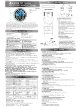
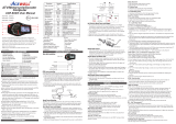
INSTALLATIONS & PARTS
Speed Sensor & Magnet Mounting
RPM Sensor Mounting
2.
1.
7.
3.
4.
6.
5.
8.
ACE-2956
Attention:
1.Align the center of the magnet to
either the sensor marking line
or the end of the sensor.
2.Installing the sensor parallel to
the vibration direction creating
optimal anti-vibration effect.
3.Be sure the gap between the magnet
and the sensor is within 8mm.
Max8mm
Vibration Direction
sensor
Max8mm
Vibration Direction
sensor
Main Unit Mounting
Fixing Screw Nut
Rubber Pad
Washer
Spring Washer
CDI
Ignition Coil
RPM-INPUT
Either One
2-5 Turns
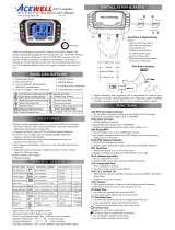
PANEL DESCRIPTIONS
1. Bar Speed Scale 5. RESET Button
2. Bar Speed 6. MODE Button
3. 1st row display: Speedometer, 7. Temp Bar: (optional)
Maximum Speed 8. LED indicator symbols
4. 2nd row display: Other functions .
Left-Direction Indicator/Green
Main-Beam Headlamp/Blue
Right-Direction Indicator/Green
Hazard Warning/ Red
Parking/Green
Direction Indicator/Green
Engine Oil/Red
Neutral Gear/Green
Reverse Gear/Red
Drive Gear/Green
Engine Coolant Temperature/Red
P
D
R
N
Rear Fog Lamp/Amber
Trailer Flashers/Green
Engine "Not In Use"/ Red
BAR RPM: Bar Graphic Tachometer
1. The bar graphic tachometer reading is always displayed at the bar graph.
2. Tachometer bar graphic displays up to 12,000 RPM.
RPM: Digital Tachometer
1. RPM is displayed in 2nd row.
2. Digital tachometer displays up to 19,900 RPM.
3. Tachometer signal picked up from either CDI or Ignition coil.
Shift Warning RPM
1. Function enables you to set up an RPM shift warning.
2. Bar-graphic tachometer flashes when RPM reaches pre-set value, and stops
flashing after you shift gear.
MAX RPM: Maximum Tachometer
1. MAX RPM is displayed on 2nd row.
2. Displays highest tachometer reading achieved after last RESET operation.
SPD: Speed Meter
1. Speed meter display is on 1st row of the screen.
2. Displays speedometer reading up to 300.0 Km/H or 187.5 mph.
MAX: Maximum Speed Meter
1. MAX is displayed on 1st row.
2. Displays highest speed achieved after last RESET operation.
AVG: Average Speed Meter
1. AVG is displayed on 2nd row.
2. Calculates average speed from last RESET.
TRIP 1 & 2: Trip Meter 1& 2
1. TRIP function registers cumulative trip distance from last RESET while bike is
being ridden.
2. Display is on 2nd row of screen.
ODO: Odometer
1. ODO registers cumulative distance traveled during motorbike operation.
2. ODO data is stored in memory, even when power is off.
RT: Riding Timer
1. Calculates total operation time from last RESET.
2. Count automatically begins with vehicle movement.
TT: Total Riding Timer
1. Calculates total operation time from the beginning of bike use.
2. Count automatically begins with vehicle movement.
3. TT data is stored in memory, even when power is off.
12/24 hour Clock
It displays 12- or 24-hour current time.
Fuel Meter (Only for models with the function)
1. Has 7 bargraphic indicator of fuel status.
2. Last bar flashes to indicate low fuel level.
℃ or �F
: Temperature Meters
1. It displays -L-
℃ or -L- �F when temperature is lower
than 0
℃ or 32 �F , and
displays-H- ℃ or -H- �F when temperature is over
180
℃ or 356�F .
2.
The LCD screen will automatic change to temperature screen and flashes the
digits of temperature when the thermo sensor detects temperature over the
presetting warning temperature; The MODE key is out of function until the
temperature cooling down and lower than the presetting waring temperature.
E
13
10R-022811
1. Signal intensity from ignition coli is dependent on vehicle type.
2. Circles 2-5 turns around ignition coil, with more turns creating steadily
signal, fewer turns creating weaker signal.
3. The computer can use all type of ignition system, only if the RPM is not
stable you must sometimes add the attached 1MOhm resistor in the wire of
the RPM input.
ACE-2956 series User's Manual
H
C
Temperature
0℃-180℃/ 32
℉
- 356
℉
℃
℉
/
1℃/
℉
±
1℃/
℉

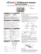
BUTTON OPERATIONS
RESET BUTTON
1. Press MODE button to the desired screen then press RESET button for
2 seconds to reset TRIP 2, MAX, and MAX RPM data from stored
values to zero individually.
2. The data of TRIP 1, AVG & RT can be reset at the same time when one
of the three data functions is being reset.
3. ODO, Clock and TT data cannot be reset.
MODE BUTTON
1. Press the MODE button to move all functions in loop sequence from one function screen to another when the speed sensor does not detect
any signal input.
SPEEDOMETER CALIBRATION
UNIT & WHEEL CIRCUMFERENCE SETTING
1. Setup operations include 12/24hour clock, shift RPM warning, numbers of engine rotations per signal, wheel circumference and units.
These must be set up step by step. The computer will automatic reversion to main screen if no button operation for 75 seconds at any
setting screen.
2. Press both MODE & RESET buttons to go into setting screen. In setting screens, press RESET button to add the flashing digit by 1,
press MODE button to confirm the digital setting and jump to next digit or next setting screen to be set. Press MODE button for 2
seconds at any setting screen to finish the setting and go to main screen.
3. It displays "12 or 24H and XX:XX-XX" symbols and AM/PM in case you select 12H.
4. Press RESET button converts 12/24H, press MODE button to complete the setting and jump to clock digit setting.
5. Press RESET button to increase flashing digit by one; press MODE button to confirm digit setting and jump to next digit.
6. Press MODE button to go to shift warning RPM setting screen after set clock.
7. It displays "rXXX00 RPM". Press RESET button to increase flashing digit by one; press MODE key to confirm digit setting and jump
to next digit.
8. Press MODE button to go to numbers of engine rotations per signal setting screen after completed shift warning RPM setting.
9. It displays "RPM SP 1r1P", the default value is 1r1P; there are 5 options: 1r1P, 1r2P, 1r3P, 1r4P, 2r1P, means the numbers of
enginerotation, “P” means number of signals from engine. For example the value 2r1P means the engine rotates 2 turns to output one
signal.
10. Press RESET button to move in loop sequence from one to another value of the 4 values. Press MODE button to confirm the setting
and go to wheel circumference setting screen.
11. In "cXXXX" display, "c" means "Circumference", following 4 default digits; flashing digit is digit to be set.
12. Press RESET button to increase flashing digit by one; press MODE button to confirm digit setting and jump to next digit.
13. Press MODE button to jump to unit setting screen.
14. It displays KM/h or M/h, each press of RESET button converts unit; press MODE button for 2 seconds to confirm unit setting and
jump to main screen.
15.It displays "SPD P-001", the pulses screen, the number of pulses into the computer per turn of the wheel. Follow item 2 of button
operation to finish the setting and jump to unit setting.
16. It displays KM/H or MPH, each press of RESET button converts unit; press MODE button to confirm unit setting and jump to
decimal point setting.
17.
It displaysm "°C or °F" , each press of RESET button converts °C or °F ; press MODE button to confirm temperature setting and jump
to temperature warning setting.
18.It displays “ODO & 00000X km”, the “X” is from odometer testing in factory, follow item 2 to set a desired odometer value and jump
to clock setting or return to Normal Mode. This setting screen will disappear when the odometer is over 30km (18.6Miles) or your
setting is over 30km
SHIFT RPM WARNING OPERATION
1. Press MODE button to the RPM screen; pull on the throttle until the desired
shift RPM warning displayed.
2. Press RESET button to confirm and set up the shift warning RPM.
3. Bar-graphic tachometer will flash to warning you shift gear.
4. Operate items 1 & 2 to readjust the shift warning RPM.
RESET
2 sec
2. Press the MODE button to move partial functions in loop from one function screen to another
when speed sensor detects signal input.
MODE
MODE
MODEMODEMODEMODE
MODE
MODE
MODE
MODE
MODE
MODE
reset
mode
reset
+
2 sec
mode
mode
mode
mode mode modemode
mode
2sec
mode
mode
mode modemode mode
resetmode mode
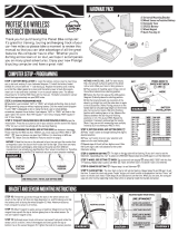
The speedo works by receiving electric pulses from the speed sensor. As the pulse rate increases the speed reading increases. To display an accurate speed reading the
distance travelled between each pulse needs to be entered in millimetres.
The first piece of information needed is the distance travelled per turn of the wheel.
Mathematically wheel circumference (in mm) = Tyre Diameter (in mm) x 3.1415 = Tire Diameter (inch) x 25.4(mm/inch) x 3.1416
To easily obtain the reading, mark the tyre and the ground where they touch. Push the wheel forward one revolution and mark where the ground again. Measure the
distance in mm - this is the rolling circumference, enter the distance into the "C" screen following the instructions below.
The second piece of information needed is the number of pulses per turn of the wheel - and this is entered into the "P" screen as below.
When using a magnet sensor system enter the number of magnets on the wheel - if you have 1 magnet then P=001, 4 magnets then P=004
If using a cable drive adaptor then enter the number of turns of the speedo cable per turn of the wheel, it will most likely be 2 or 3.
When using a factory speed sensor on the front hub, front sprocket or inside the gearbox then the number of teeth on the sensor need to be counted (and multiplied by the
drive ratio in some cases).
Always check your calibration against a GPS and ensure that the displayed speed is greater than the speed shown on GPS.
To increase a speed reading increase the number entered into the "C" screen.
-
 1
1
-
 2
2


Acewell ACE-2956 series User manual
- Category
- Bicycle accessories
- Type
- User manual
Ask a question and I''ll find the answer in the document
Finding information in a document is now easier with AI
Related papers
-
 Acewell ACE-27 series User manual
-
 Acewell ACE-28 series User manual
-
 Acewell ACE-38xx series User manual
-
Acewell ACE-MD085-5 Series User manual
-
 Acewell ACE-31 SERIES User manual
-
 Acewell ACE-3200 Series User manual
-
 Acewell ACE-395X-XX series User manual
-
 Acewell ACE-64 Series User manual
-
 Acewell MD-052-3 Series User manual
-
 Acewell ACE-2XX User manual


Other documents
-
Dakota Digital SIM-1a-M Technical Manual
-
PYLE Audio PBKCM4WL User manual
-
Giant Continuum 7 User manual
-
-
-
 Planetbike Protege 9.0 wireless - 2016 Owner's manual
-
Viper ACEWELL 1100 Quick start guide
-
 HER CHEE ACE-7XXX series User manual
-
Acumen SP500 User manual
-

