Page is loading ...

ATV/Motorcycle Computer
ACE-2XX User Manual
23
6
7
4 5
1
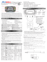
Speed Sensor:
The ACE-2XX can use either a 2 wire hall sensor or a reed sensor
when it is connected to the bike’s power.
FEATURES
Displays speedometer, Trip and odometer and bar-graphic fuel gauge
at the same me.
Built-in 4-6 LED indicators for different applicaons and backlight.
Odometer and total riding mer are always kept in memory.
Metric/Empire unit opons are available.
Adjustable wide wheel circumference seng from 1 to 3999mm.
Fuel gauge includes +/- 100, 250 and 510 Ohm opons for fuel sender
input resistance, as well as “fuel gauge off” mode.
Includes bracket, speed sensor, fing kits and wiring harness.
SPECIFICATIONS
Power Input
Speed Sensor
Wheel circumference setting
Dimensions
DC 9-18V
Reed Sensor or Hall sensor with 2 wires
1mm-3999mm
96.7mm x 53.9mm x 24.5 mm
Function Specifications
Simbolo
Speedometer
2.4-399 km/h
(248 MPH)
0.0-999.9 KM/Miles
Maximum speed 2.4-399 KM/h (248 MPH)
Trip meter 1&2
Riding timer 0-99H59`59``
+/- 100Ω, 250Ω, 500Ω options and Off
Total Riding Time 0-999999H
Odometer
TRIP 1/2
12/24 Hour Clock 0:00`-11H59`/23H59`
RT
Bar-Fuel Gauge
Km/H /
MPH
0- 999999 KM, 0-624999 Miles
ODO
Average speed
AVG
2.4-399 KM/h (248 MPH)
MAX
T T
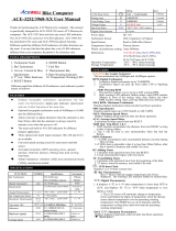
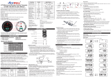
Reed Speed Sensor and Magnet:
1. This sensor is universal sensor for motorcycle, find a rotang part
to install magnet (for example disk, sprocket or drivesha) and a
locaon to install the sensor where it can be aligned to the magnet.
2. Align the center of the magnet to either of the sensor marking lines
or the side of the sensor.
3. Installing the sensor parallel to the vibraon direcon creates
oponal an-vibraon effect.
4. Make sure the gap between the magnet and the sensor is
within 8mm.
Hall Effective Speed Sensor and Magnet:
1. This is universal sensor for ATV front or rear wheel installaon
or motorcycle front wheel installaon. For some fitments an
accessory speed sensor holder may need to be purchased.
2. Find a rotang part to install magnet (for example disk, sprocket
or drivesha) and a locaon to install the sensor where it can be
aligned to the magnet
3. Align the center of the magnet to center of side face of the sensor.
4. Make sure the gap between the magnet and the sensor is
within 5mm.
Specific Hall sensors:
Cable drive adaptors for most bikes originally fied with cable
driven speedometers or milemeters are available. When using these
cables it is necessary to divide the circumference seng by the
number of rotaons of the cable per rotaon of the wheel.
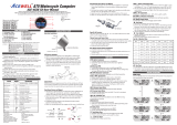
Thanks for purchasing this ATV/Motorcycle/Scooter computer; this manual is designed for ACE-2XX series. Each model has 4-6 LED indicators.
Different model has different LED indicators. You may found above photo has different LED indicators from your computer; the photo above is for reference only.
PANEL DESCRIPTIONS
1. 1 row: Speedometer
2. 2 row: Trip 1&2, RT, AVG
3. 3 row: ODO, TT, MAX
4. RESET Buon
5. MODE Buon
6. Fuel Gauge
7. LED Indicators
st
nd
rd
Left-Direction Indicator/Green
Main-Beam Headlamp/Blue
Right-Direction Indicator/Green
Hazard Warning/ Red
Direction Indicator/Green
Engi ne Oi l / Red
Neutral Gear /Green
Reverse Gear /Red
R
N
Max. 8mm
Vibration Direction
sensor
Max. 8mm
Vibration Direction
sensor
Max. 8mm
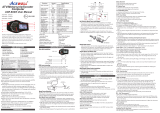
INSTALLATION
Rubber Pad
Washer
Spring Washer
Fixing Screw Nut
Main Unit Mounting
Main Unit
Mounng
English
10R-039949

BUTTON OPERATIONS
MODE BUTTON
Press the MODE buon to move between all funcons in loop
sequence as “→ ” path from one funcon screen to another.
1. Setup operaons include 12/24hour clock,, wheel circumference,
units and fuel meter input resistance selecon. These must be
set up step by step. The computer will be automac reversion to
normal mode if no buon operaon for 75 seconds at any seng
screen.
2. Press both MODE & RESET buons to go into seng screen. In
each seng screen, press RESET buon to increment the flashing
digit by 1 or convert units, press MODE buon to confirm the digit
seng and jump to next digit or next seng screen to be set. Press
MODE buon for 2 seconds at any seng screen to finish the seng
and go to normal mode.
3. It displays "12 or 24H and XX:XX-XX" symbols as well AM/PM in
12H mode. Operates buons as per descripons of item 2 to finish
clock seng and jump to wheel circumference seng.
4. In "cXXXX" display, "c" means "Circumference", following 4 default
digits; flashing digit is digit to be set. Follow the item 2 of buon
operaon to finish the wheel circumference seng and jump to
unit seng.
5. It displays KM/H or MPH, each press of RESET buon switches
units; press MODE buon to confirm unit seng and jump to fuel
sensor resistance seng.
6. It displays “100r” and fuel tank symbol, follow the item 2 to select
100, 250, 510ohm, oFF, -100, -250 and -510Ohm and jump to jump
to clock seng or return to Normal Mode. The fuel meter bar will
disappear if you select oFF mode.
Clock,Wheel Circumference,Units and Fuel Gauge Resistance SET UP
RESET BUTTON
1. Press MODE buon to get to the desired screen then press
RESET buon for 2 seconds to reset Trip 2, MAX SPD and
AVG speedometer from stored values to zero individually.
2. The data of Trip 1, AVG & RT can be reset at the same me
when one of the 3 data funcons is being reset.
3. ODO, clock and TT data cannot be reset.
Mode
FUNCTIONS
Km/H or MPH: Speedometer
Displays speed meter up to 399 Km/H or 248 MPH.
MAX: Maximum Speed Meter
Displays highest speed achieved since last Reset operaon.
AVG: Average Speed Meter
It calculates average speed since last RESET. The AVG is calculated
from TRIP 1 be divided by RT.
TRIP 1&2: Trip Meter 1 and 2
TRIP funcon accumulates trip distance since last RESET as long as
bike/vehicle is in moon.
ODO: Odometer
ODO accumulates total accumulated distance traveled during
bike moving.
RT: Riding Timer
1. Calculates total running me since last RESET.
2. Count automacally begins with movement.
TT: Total Riding Time
1. Calculates total riding me traveled during bike moving.
2. TT data is stored in memory, and cannot be reset.
: 12/24 hour Clock
It displays 12 or 24 hour current me.
: Fuel Gauge
1. Have 7 bars to indicate how much fuel remains.
2. Built-in +/- 100, 250 and 510Ohm fuel sender resistance,
the fuel bar display will disappear in when you select “ off ”
mode.
3. Last bar flashes to indicate low fuel level automacally.
Mode
Mode
Mode
Mode
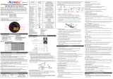
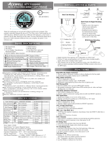
Tire Size
Circumferen
ce number
(mm)
Tire Size
Circumferen
ce number
(mm)
Tire Size
Circumferen
ce number
(mm)
23 inch
24 inch
25 inch
26 inch
19 inch
20 inch
21 inch
22 inch
15 inch
16 inch
17 inch
18 inch
1835
1915
1995
2075
1516
1596
1676
1756
1197
1277
1357
1436
WHEEL CIRCUMFERENCE TABLE
1. The details below have been calculated using following formula: Tire
Diameter (inches) x 25.4(mm/inches) x 3.1416 = wheel circumference
(in mm).
2. Idenfy the re size of your ATV/Motorcycle when you need to change
different re size and key in the corresponding number shown in the
following chart.
3. The computer calculates the wheel rotang length between 2 passes
of the magnet; use this table to find the sengs when you are using
a reed sensor or an universal hall sensor with magnet to measure
your speed.
4. If you are using a cable drive speed sensor then divide the number in
the above table by the number of turns of the cable drive for each
revoluon of the wheel. For example if 1 wheel revoluon equals
5 turns of speed cable then the wheel circumference has to be
divided 5.
5. You can use more magnets, but the wheel circumference seng
must be divided by the number of magnet you installed.
RESET
2 sec

RESET+
MODE
2 Sec
RESET
Mode
Mode
Mode
Clock: Hour
Clock: Minute
Mode
Mode
Wheel Size: 1 ~ 3999 mm
Unit: KM/H / MPH
Fuel Type: 100/250/510/-100/-250/-510/off
Clock,Wheel Circumference,Units and Fuel Gauge Resistance SET UP
Clock: Second
Mode
RESET
RESET
RESET
RESET
RESET
RESET
RESET
RESET
Mode
Mode
2 sec
/