Page is loading ...

ACE-6XXX User Manual
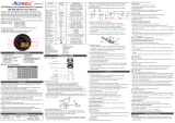
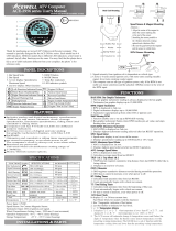
RPM sensor mounting:
Reed Speed Sensor and Magnet:
1. This sensor is universal sensor for motorcycle, find a rotang part to
install magnet (for example disk, sprocket or drivesha) and a locaon
to install the sensor where it can be aligned to the magnet.
2. Align the center of the magnet to either of the sensor marking lines or
the side of the sensor. The magnet must not travel down the body of
the sensor.
3. Installing the sensor parallel to the vibraon direcon creates oponal
an-vibraon effect.
4. Make sure the gap between the magnet and the sensor is within 8mm.
Max. 8mm
Vibration Direction
sensor
Max. 8mm
Vibration Direction
sensor
Speed Sensor Mounting:
ACEWELL has several speed sensors; the unit may include one of them.
If the model is intended to be connected to a gearbox electronic speed
output to obtain the speed reading, no speed sensor will be included.
FUNCTIONS
RPM: Digital Tachometer
1. It displays digital tachometer up to 19,990RPM and displays 19,999
rpm when tachometer is over 20,000rpm..
2. It has 2 wires to pick up RPM signal, the yellow wire is to connect to
Plug,and white wire is for signal from ECU or Ignion coil.
Shift Warning RPM
1. The funcon enables you to set up a shi warning RPM.
2. A indicator flashes when RPM reaches 500rpm before seng value.
3. Shi warning LED indicator flashes when RPM reaches seng value, and stops
flashing aer you shi gear.
Km/H or MPH: Speedometer
1. Displays speed mete r up to 399.9 Km/H or 248.5 MPH.
2. The maximum frequency of soware divider is 7K Hz.
3. With a small wheel size and large number of pulses per wheel
revoluon it may not be possible to display very high speeds.
MAX: Maximum Speed Meter
Displays highest speed achieved since last Reset operaon
AVG: Average Speed Meter
It calculates average speed from last RESET. The AVG is calculated from
TRIP1 be divided by RT.
TRIP 1&2: Trip Meter 1&2
TRIP funcon accumulates trip distance since last RESET as long as bike/
vehicle is moving.
Specific Hall sensors:
Cable drive adaptors for most bikes originally fied with cable driven
speedometers or odometers are available. When using these cables it
is necessary to divide the circumference seng by the number of
rotaons of the cable per rotaon of the wheel.
Thermo Sensor and Sensor Tube:
1. The unit includes a water temperature sensor; you may have to
purchase a suitable water pipe temperature sensor tube to install
the sensor on some bikes.
2. Cut the water pipe, insert the temperature tube into the pipe and
secure it by aached pipe clamps.
3. Screw the sensor into the tube.
4. If your vehicle is fied with a thermostat that stops water flowing to
the radiator when the engine is cold, you will not get a reading unl
the thermostat opens.
5.Custom sensors are available for carbureed bikes to replace the
original sensor.
Wire Remote Control Switch Installation:
1. Install the switch arm on handlebar.
2. Install the switch box to one of 3 fixing holes and adjust switch box to
a suitable angle.
3. Plug the switch box connector into the main unit matching connector.
Hall Effective Speed Sensor and Magnet:
1. This is universal sensor for ATV or motorcyclefront or rear wheel
installaon or motorcycle front wheel installaon. For some fitments
an accessory speed sensor holder may need to be purchased.
2. Find a rotang part to install magnet (for example disk, sprocket or
drivesha) and a locaon to install the sensor where it can be aligned
to the magnet
3. Align the center of the magnet to center of side face of the sensor.
4. Make sure the gap between the magnet and the sensor is within 5mm.
INSTALLATION & PARTS
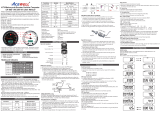
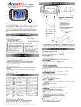
Main Unit Installation:
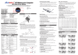
PANEL DESCRIPTIONS
FEATURES
1. Tachometer Scale
2. Needle Tachometer
3. 1st row: Speedometer
4. 2nd row: Other funcons
5. Gear Indicator
6. RESET Buon
7. MODE Buon
8. RPM Shi Warning Indicator
9. Bar Temperature gauge
10. Bar Fuel gauge
11. LED indicators
Different models have different LED indicators, each indicator symbol
means as below:
SPECIFICATIONS
ACE-64XX: 9,000rpm
ACE-65XX: 12,000rpm
ACE-66XX: 15,00rpm
Needle tachometer, integrated digital funcons and 6-10 LED
indicators for different models.
Displays needle tachometer, speedometer, bar temperature and
fuel gauges, gear indicator and one other funcon simultaneously.
Features a 99 lap mer and an oponal cable connected remote
control switch.
Gear indicator which calculates gear by comparing speed and RPM.
An oponal air temperature sensor can measure outside
temperature.
Fuel gauge full and empty resistances are fully adjustable and it can
connect to sender units with resistance range up to 990 ohms. In
reserve mode, the fuel gauge is not displayed and fuel symbol lights
when the input wire is connected to -ve. The gauge can be switched
off enrely if not required.
Flexible baery warning voltage seng from 11.0 to 15.0V.
Speedometer can show nearest 1 or 0.1 mph or km/h speed if
required by user. E.g. 100 or 100.5.
Highly visible 12mm shi warning LED indicator.
Allows end user to adjust odometer when the odometer is less than
30km / 18.6 miles.
Universal wheel circumference seng range from 1 to 3999mm.
Includes bracket, RPM sensing wire, hall or reed speed sensor,
fing kits, wiring harness and temperature sensor.
Excellent water resistant, an vibraon structure and noise
immunity design.
Power Input DC 12V
Tachometer Sensor CDI or Ignition Coil Signal
Speed Sensor Reed or hall Sensor
Temperature Sensor Thermo Sensor
Speed input divider setup 1-199 Pulses
Maximum speed input frequency 7K Hz
Wheel circumference setting 1mm-3999mm
Dimensions 130.6mm x83.4mmx31.3mm
Thanks for purchasing the ATV/Motorcycle/scooter computer; this
manual is specifically designed for ACE-6XXX-XX series. Different series
have different needle tachometer scales, each series has different
models, each model has different LED indicators. You may find that the
photo has a set of LED indicators different from your computer, the
photo is for reference only.
Different series with different needle tachometer scales
are as bellows:
Main Unit
Le direcon indicator/Green
Main-beam headlamp/Blue
Right direcon indicator/Green
Hazard Warning/ Red
Parking/Green
Direcon indicator/Green
Engine oil / Red
Neutral Gear /Green
Reverse Gear /Red
Drive Gear /Green
Engine coolant temperature/ Red
P
D
R
N
Rear fog lamp/Amber
Flash Trailer/Green
Engine in out of use/ Red
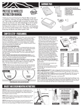
Functions SpecificationsSymbol
Needle Tachometer
ACE-64XX 9,000rpm
ACE-65XX 12,000rpm
ACE-66XX 15,000rpm
Digital Tachometer
Speedometer
Maximum speed
Average speed
Temperature 1
Temperature 2
Max. Temperature
Trip meter 1&2
Trip 1&2
Odometer
12/24 Hour Clock
Riding timer
ODO
RT
RPM
Km/h / MPH
MAX SPD
AVG SPD
10-19,990 rpm,
2.4-399.9 km/h (248.5 MPH),
2.4-399.9 Km/h (248.5 MPH),
2.4-399.9 Km/h (248.5 MPH),
0
°C
-180
°C
/32
°F
-356
°F
0
°C
-180
°C
/32
°F
-356
°F
0
°C
-180
°C
/32
°F
-356
°F
<0
°C
display -L-, >180
°C
display -H-
0.0-999.9 KM /624.9Miles
0 - 999999 KM, 0-624999 Miles
AM/PM 0:00’ – 11H59’ / 23H59’
0-99H59`59``
Gear indicator
Bar-Fuel Gauge
Bar-Temperature
1-7 Bar-graphic or off mode
Maintain reminder
9999km, 9999 hours or oFF
LAP
N, R, 1, 2,…8 gears and off mode
Adjustable 10Ω -990Ω, reserve mode, or not displayed
99 laps
LAP
Total Riding Time
Total Hour meter
Voltage Gauge
TT
0-999999H
0-999999H
8.0-18.0 Volt and battery warnings
V
HRTT
Spring Washer
Washer
Rubber Pad
Fixing Screw Nut
Bracket
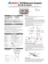
1.Connect either the yellow or white wire to sense the RPM signal.
2.The yellow wire can be wrapped around the spark plug lead.
a.Signal strength from the ignion coil is dependent on coil type.
b.Coil 2-5 turns around spark plug lead, the more turns the stronger the signal. A
weak signal will not show a reading on the screen whereas a very strong signal
will have a reading which is too high or very jiery. If the reading is incorrect
then try pung the 1MΩresistor which is included in the box inline in the
sensor wire.
3.If the signal is sll unstable, please try to connect the white wire to either the
ECU rev counter output or to the primary side of the coil or to the pulse wire on
an acve spark plug cap.
10R-0312652
1
11
2
4
5
7
8
10
9
3
6
1
2
MAX
ODO: Odometer
1. ODO accumulates total distance traveled.
2. ODO datemory and cannot be reset.
RT: Riding Timer
1. Calculates total running me since last RESET.
2. Counter automacally begins with movement.
TT: Total Riding Timer
1. Calculates total riding me from the beginning of the bike.
2. TT data is stored in memory, and cannot be reset.
HRTT: Hour Meter
1. Calculates total engine operaon me since installaon RESET.
2. Count automacally begins with engine starng.
3. HRTT data is stored in memory, and cannot be reset.
: 12/24 hour Clock
It displays 12 or 24 hour current me.
1 and 2:Temperature Meter 1 & 2
1. It measures and displays from 0
°C
-180
°C
/ 32
°F
-356
°F
.
2. It displays -L-
°C
or -L-
°F
when temperature is lower than 0
°C
(32
°F
) or disconnected
temperature sensor, and displays -H-
°C
or –H-
°F
when temperature is over 180
°C
or
356
°F
.
3. User can measure engine temperature with sensor 1 and ambient air temperature with
sensor 2.
4. The bar-temperature and digits of temperature as well temperature LED indicator flash
when the thermo sensor detects temperature higher than the maximum preset
temperature.
2: Low temperature warning of temperature input 2
1. Temperature input 2 has an automac low temperature warning which requires no setup
when temperature 2 input is switched on in the setup menu and a temperature sensor is
connected to it.
2. The LED indicator and the icon on the LCD flash when temperature drops below 3
and stop flashing when the temperature rises above 3 .
3. The digital temperature meter displays “-L-“ when temperature is less than 0
MAX TEMP 1& 2: Maximum Temperature 1 & 2
Displays highest temperature achieved since last Reset operaon.
: Digital Voltage and Baery Warnings
1. It checks bike’s baery and charging systems health.
2. It has 3 modes to be set, b-on, b-oFF and b-HI, all 3 modes range is from 11.0V to 15.0V.
3. The “b-on” means baery warning on voltage, when the voltage falls below this the
LED will flash.
4. The “b-off” means baery warning off voltage, b-off voltage must larger than b-on
voltage.
5. The “b-HI” means baery high voltage, it comes on to warn that the baer has over
charging.
:
Gear Indicator
1. The gear indicator calculates gear by comparing speed and RPM then displays gear
posion.
2. User has to train the gear indicator before use it.
SCAN: Scan funcon
1.The 2nd row of LCD data will be changed automacally every preset number of
seconds if the SCAN is selected. The scan period is from 1 to 20 seconds.
2. All funcons will be manual operaons when SCAN is switched off.
: Fuel Gauge
1. Has 7 bars to indicate how much fuel remains.
2. To use as a fuel gauge, the user enters the sender ‘empty’ resistance between 10
and 990 ohms and the sender ‘full’ resistance between 10 and 990 ohms. The
computer produces a linear scale of bars between these two resistances. When less
than 10% fuel remains the gauge will flash and the warning LED if fied will light.
3. To use as a reserve indicator, connect the reserve switch to the input and put into
“rEs” mode. When the switch pulls the input to –ve the LED warning will light. On
vehicles with temperature based sensors a 68Ω 5W resistor needs to be connected
between the input wire and 12v (switched).
4. If the gauge and warning lamp are not required they can be switched off
: Bar Thermometer*
1.Have 7 bars to indicate engine temperature.
2.The 4th bar counts from boom be turned on and over temperature LED flashes when
thermometer reaches the preset warning temperature, each +/-15
˚C
lights on/off a bar
base on the 4th bar.
3.The bar-temperature flashes when the measured temperature is higher than the preset
warning temperature.
LAP:
Lap Timer
1.It can keep up to 99 sets of lap mer of each circle.
2.The funcon must be operated by an addional wiring remote control
switch or an accessory IR receiver/transmier or a magnec field sensor.
Freezing Time for Lap mer:
1.The freezing me is designed to avoid addional count signal during the set me.
2.The set range is from 1 to 20 seconds.
ATV/Motorcycle/Scooter
Computer

1. Press the MODE buon to move between all funcons in
sequence as “ ” from one funcon screen to another when the .
speed sensor does not detect any signal input.
2. Press the MODE buon to move paral funcons in loop sequence
as “ ”when speed sensor detects signal input.
BUTTON OPERATIONS
MODE BUTTON
Gear Indicator Tranning Operations:
Optional Remote Control Switch for LAP timer
1. Setup operaons include 12/24hour clock, bar rpm scale, shi warning
RPM, numbers of engine rotaon per signal, wheel circumference, signal
divider, units, maintain reminder, units of temperature, temperature
warning, fuel meter input resistance selecon and odometer adjustment.
These must be set up step by step. The computer will be automacally
revert to normal mode if no buon is pressed for 75 seconds at any
seng screen.
Clock, RPM, Wheel, Divider, Unit, Maintain, Thermometer, fuel meter and ODO SET UP
Tire Size
Circumference
number
(mm)
Tire Size
Circumference
number
(mm)
Tire Size
Circumference
number
(mm)
23 inch
24 inch
25 inch
26 inch
19 inch
20 inch
21 inch
22 inch
15 inch
16 inch
17 inch
18 inch
1835
1915
1995
2075
1516
1596
1676
1756
1197
1277
1357
1436
WHEEL CIRCUMFERENCE TABLE
1. The details below have been calculated using following formula: Tire
Diameter (inches) x 25.4(mm/inches) x 3.1416 = wheel circumference
(in mm).
2. Idenfy the re size of your ATV/Motorcycle when you need to change
different re size and key in the corresponding number shown in the
following chart.
3. These values are approximate and will differ for different brands of
tyre, we would always recommend that you measure the distance
travelled per revoluon of the wheel in mm and enter this into the
computer.
4. The computer calculates the wheel rotang length between 2 passes
of the magnet; use this table to find the sengs when you are using a
reed sensor or an universal hall sensor with magnet to measure your
speed.
5. If you are using a cable drive speed sensor then enter the number of
turns of the cable perf the wheel into the pulses screen.
6. You can use more magnets, enter the number of magnets fied into
the pulses screen.
7. If using a sprocket tooth counter speed sensor or internal pulse
gearbox speed sensor enter the number of pulses per wheel
revoluon into the pulses screen.
2. Press both MODE & RESET buons to go into seng mode. In seng
mode, each press of the RESET buon increments the flashing digit by 1
or converts units. Press MODE buon to confirm the digit seng and
jump to next digit or next seng screen to be set. Press MODE buon for
2 seconds at any seng screen to finish the seng and go to normal mode.
Shift Warning RPM Operation
1. Press MODE buon to the RPM screen; pull on the throle unl
the desired shi warning RPM.
2. Press RESET buon to confirm and set up the shi warning RPM.
3. Bar-graphic tach ometer and warning LED will flash to warning you
shi gear.
4. Press RESET buon for 2 seconds at the RPM screen to re-adjust
the shi warning RPM.
RESET BUTTON
Reset buon cycles through funcons in reverse order
DATA RESETTING AND PROGRAMMING MODES
1. Press MODE or RESET buon to reach the desired screen then
press RESET buon for 2 seconds to reset TRIP 2, MAX SPD, MAX
RPM and MAX data from stored values to zero individually. The
maintain reminder data will be reset to the preset value rather
than zero.
2. The data of Trip 1, AVG & RT will all be reset at the same me when
one of the 3 data funcons is being reset.
3. ODO, clock, HRTT and TT data cannot be reset.
4. Gear indicator flashes the default 0 gears.
5. Press RESET buon to select the number of gear, user can select 4-8 gears or
“0” to disable the gear funcon.
6. Press MODE buon to confirm the number of gears and go to the number
gear rao seng mode.
7. It displays and flashes “1”, shi bike’s gear to the 1st gear, run the engine to
between 2000-4000RPM.
8. Hold the speed and the RPM for about 5 seconds unl the “-“flashing. The
flashing “-“aer the gear “1” means the 1st gear be set.
9. Press MODE buon to confirm the set and go to the 2nd gear seng.
10. It displays and flashes “2”, shi bike’s gear to the 2nd gear, run the engineto
between 2000-4000RPM.
11. Hold the speed and the RPM for about 5 seconds unl the “-“flashes. The
flashing “-“aer the gear “2” means the 2nd gear is set.
12. Press MODE buon to confirm the seng and go to next gear seng.
13. Repeat the same operaons as items 11-14 to set other gears unl the last
gear is set. Press MODE buon to return to normal mode.
14. At gear indicator seng mode, press and hold MODE buon for 2 seconds
to abort the seng if you need to re-set at any seng screen.
1. The remote control switch has 2 buons: MODE and LAP. The MODE buon
has the same funcon as on the main unit.
2. Press and hold the LAP buon for 2 seconds to go into the LAP mode.
3. LAP Record operaons:
a. In LAP mode, press LAP buon to convert start or stop the LAP recording
funcon, each press of MODE buon records a set of data LAP and
displays LAP mer for 3 seconds then changes display to speed mode
automacally, press and hold the LAP buon for 2 seconds to go out LAP
mode and return to normal mode.
b. The first data of recording funcon will be renewed by new data when lap
exceeds 99 laps, then each new data renews earliest data one by one.
LAP review operations:
1. In the LAP mode, press MODE buon to review the 1st stored data, it
displays number of lap and lap mer.
2. Press the RESET buon to switch between lap mer of the same LAP; each
press of the MODE buon displays data for the next lap.
3. Press and hold LAP buons for 2 seconds to go out LAP mode and return to
normal mode.
Follow the item 2 to set sensor type of LAP mer and jump to freezing
me seng.
20. **It displays flashing 01 and SEC, the range is from 01 to 20 seconds,
the freezing me seng will ignore signals received by the unit within
the set freezing me aer it received a signal. Follow the item 2 to set
freezing me and jump to odometer seng.
21. It displays “ODO & 00000X km”, the “X” is from odometer tesng in
factory, follow item 2 to set a desired odometer value and jump to
clock seng or return to Normal Mode. This seng screen will
disappear when the odometer is over 30km (18.6Miles) or your seng
is over 30km
Mode
Mode
Mode
Mode
Mode
Mode
Mode
Mode
Mode
Mode
Mode
Mode
Mode
Mode
Mode
Mode
Mode
Mode
Mode
Mode
Mode
Mode
Mode
Mode
Mode
Mode
Mode
2 sec.
RESET
Mode
+
2 sec.
RESET
2SEC
3. It displays "12 or 24H and XX:XX:XX " symbols and AM/PM when you
select 12H. Operate buons as described in item 2 to finish clock
seng and jump to shi RPM warning seng.
4. It displays the default "RPM r06500", the digit “0” flashes. Follow the
item 2 of buon operaon to finish the shi RPM warning seng and
jump to engine specificaon seng.
5. It displays "RPM SP 1r1P", the default value is 1r1P; there are 6 opons:
1r1P, 1r2P, 1r3P, 1r4P, 2r1P, 3r1P,. “r” means the numbers of
enginerotaon, “P” means number of signals from engine. For example
the value 2r1P means the engine rotates 2 turns to output one signal.
6. Press RESET buon to move in loop sequence from one to another
value of the 6 values. Press MODE buon to confirm the seng and go
to speed sensor type screen.
7. It displays SPD SEn HALL or SPD SEn rEEd, HALL type is for Acewell's
unique 2 wires hall sensors only, rEEd type is for reed sensors, gear
sensors and signals from ECU. A gear sensor has 3 wires and must be
powered from the bike. Follow item 2 of buon operaon to confirm
the sensor type and jump to wheel circumference seng screen.
8. In "SPD cXXXX" display, "c" means "Circumference", following 4 default
digits; flashing digit is digit to be set. Follow the item 2 of buon
operaon to finish the wheel circumference seng and jump to signal
divider seng.
9. It displays "SPD P-001", the pulses screen, the number of pulses into the
computer per turn of the wheel. Follow item 2 of buon operaon to
finish the seng and jump to unit seng.
10. It displays KM/H or MPH, each press of RESET buon converts unit;
press MODE buon to confirm unit seng and jump to decimal point
seng.
11. It displays “99.9Km/H SPD & on” or “99Km/H SPD & oFF”, the decimal
point will disappear when Off is selected. Follow the item 2 of buon
operaon to finish the decimal seng and jump to maintain reminder
seng.
12. It displays and TRIP, RT or oFF, TRIP is 1000km (621Miles) and RT is
100 hours by default. Follow the item 2 of buon operaon to finish
the maintenance reminder seng and jump to voltage warning seng.
The maintenance reminder funcon will be not be shown when “OFF”
is selected.
13. It displays “ b-on and a flashing numbers of voltage” to be set, “b-on”
means baery warning on voltage – when the voltage falls below this
the LED will flash, seng range from 11.0 to 15.0V. It displays “
b-off and a flashing numbers of voltage”, “b-off” means baery
warning off voltage, seng range from 11.0 to 15.0V to, but b-off
voltage must larger than b-on voltage – when this voltage is exceeded
the LED will go off. It displays “ b-HI and a flashing numbers of voltage”
to be set, “b-HI” means baery warning on voltage – when the voltage
is exceeded the LED will come on, seng range from 11.0 to 15.0V“.
Follow the item 2 of buon operaon to finish the voltage warning
seng and jump to thermometer 1 seng.
14. It displays " 1
°C, °F or oFF", each press of RESET buon converts ,°C or °F
Off, the temperature bars will disappear when you select oFF mode;
press MODE buon to confirm temperature seng and jump to
temperature 1 warning seng.
15. It displays " 1 XXX" and the selected unit. Follow the item 2 of buon
operaon to finish the temperature warning seng and go to
thermometer 2 seng.
16. thermometer 2 seng It displays "** 2
°C , °F or oFF", each press of
RESET buon converts
°C, °F or Off, press MODE buon to confirm
temperature seng and jump to scan seng.
17. It displays SCAn and on or oFF, It displays “flash 01 & SCAn” if you
select Scan on, it means the me in seconds to display each funcon,
for example 05 means every 5 seconds auto change to the next
funcon, the set range is 01-20. Follow the item 2 of buon operaon
to finish the SCAN seng and go to fuel sensor resistance seng.
18. It displays “on, off or rES” and , it displays fuel tank and full bars as
well flash XXXXr, it means full tank resistance seng, the seng range
of “on” from 10r to 1000r. It displays fuel tank and one bar as well as
flash XXXXr, it means empty fuel sensor resistance seng. Follow the
item 2 to select a resistance same as your fuel sender and jump to
sensor type of **LAP mer seng. The fuel meter bar will disappear if
you select oFF mode. In “rES” mode connecng the input wire to 0v
can bring on the fuel symbol and/or LED indicator instantly.
19. It displays Ir, EF1, EF2 or EF3, Ir means you elect IR receiver as the
sensor for LAP mer, and the selecon of EF1, 2 or 3 is a magnec
field sensor for LAP mer, the number of 1, 2 or 3 is means the
number of magnec sensor in track, for example EF2 means the track
has 2 magnec sensor and it will combine 2 sensing signals in one.
1. If using a rear wheel or gearbox speed sensor, put bike on a rolling road or
securely mounted centre stand, if measuring front wheel speed the following
can only be done if the vehicle is moving.
2. Change the LCD screen to display digital RPM.
3. Press and hold MODE buon for 2 seconds to go into the number of gears
seng mode.
Speed decimal opon:
1.User can decide to display speed to 1 or 0.1 mph / km/h.
2.Follow the item 11 of set up mode to opon the decimal of speedometer.
: Maintenance Reminder
1.The maintenance reminder can set by either trip meter or hour meter, and
an “Off” mode to switch it off.
2.The trip meter maintenance can be set up to 9999km.
3.The HRT maintenance reminder can be set up to 9999 hours.
Mode
Mode
Mode
Mode
Mode
Mode
Mode
Mode
Mode
Mode
Mode
Mode
Mode
Mode
Mode
Mode
Mode
Mode
/