SteamSpa BKT450CH-A Installation guide
- Category
- Sanitary ware
- Type
- Installation guide
This manual is also suitable for

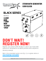
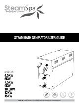
STEAM BATH GENERATOR
USER GUIDE
4.5KW
6KW
7.5KW
9KW
10.5KW
12KW
MODELS
BLACK SERIES
V3.3
Steam Spa PHONE: 800-856-0172 FAX: 866-560-1060 http://steamspa.com [email protected]
W
H
I
S
P
E
R
Q
U
I
E
T
B
U
I
L
T
-
I
N
A
U
T
O
D
R
A
I
N
C
O
N
T
I
N
U
O
U
S
S
T
E
A
M
Q
U
I
C
K
S
T
A
R
T
DON’T WAIT!
REGISTER NOW!
Register your product within 90 days to ensure your steam bath
generator is recognized as an ofcial purchase and is eligible for
warranty coverage.
Mail in the completed registry card (Pg. 2) or register online at
www.SteamSpa.com/register.

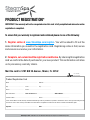
PRODUCT REGISTRATION*
IMPORTANT: Your warranty will not be recognized unless this card is fully completed and returned or online
registration is completed.
To ensure that your warranty is registered and conrmed please do one of the following:
1. Register online at www.SteamSpa.com/register. You will be asked to fill out the
same information you would in the registration card. Registering online is fast, secure
and ensures we receive your information.
2. Complete, cut-out and mail the registration card below. By returning this registration
card we confirm the date of purchase for your new product. This confirmation will allow
us to process any warranty claims.
Mail the card to: 5701 NW 35 Avenue, Miami, FL 33142
Steam Spa PHONE: 800-856-0172 FAX: 866-560-1060 http://steamspa.com [email protected]
Product Registration Card
Name ..................................................................................... Address ....................................................................................................................
City ............................................... State ........................... Zip ..............................
Phone ........................................... Email ....................................................................
Date of Purchase........................... Order or Purchase # .................................................... SKU or Model # .........................................................
Installer’s Name ..................................................................... Phone ................................................................................
I have read the Owner’s Guide carefully and understand and agree that any installation, operation or maintenance of the steam generator and generator
accessories must be done strictly in accordance with instructions and guidelines contained in the owner’s manual and installation guide.
Signature.............................................................................. Date ..................................................................................
CUT ALONG
DOTTED LINE.

SteamSpa PHONE: 800-856-0172 FAX: 866-560-1060 http://steamspa.com [email protected]
Page 3
INSTALLATION & USER GUIDE
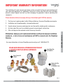
IMPORTANT WARRANTY INFORMATION!
The installation of a quick connect and release system is essential to the care and maintenance of
your steam bath generator unit. Additionally, the use of an inline water filter with fresh cartridges
prevents mineral deposit and built up from damaging the generator’s internal plumbing and
compnents.
Please be advised failure to comply with any of the following will VOID the warranty.
1. The User must register product within 90 days of delivery. See www.SteamSpa.com/register.
2. Installation must be performed by a licensed professional.
3. A quick release & pressure reducing valve must be used for reliable periotic maintenance.
4. An inline water filter must be installed to prevent mineral deposit and build up.
5. Filter cartridge must be replaced no later than every 6 months.
Malfunctions, damages, parts replacement and labor resulting from improper installation,
negligence, or lack of care and maintenance will NOT be covered under the SteamSpa
Warranty.
For more information visit www.SteamSpa.com/warranty or call 1-800-856-0172.
Quick Connect Kit
STMKIT
Replaceable Filter
Cartridges
G-STEAMFILT-CAR
Inline Water Filter
G-STEAMFILT
1
2
3
STEAM QUICK RELEASE & PRESSURE REDUCTION KIT
w/ WATER FILTER PLUS EXTRA CARTRIDGES
STMKIT-02

Steam Spa PHONE: 800-856-0172 FAX: 866-560-1060 http://steamspa.com [email protected]
This peel-n-stick warning label must be applied to the wall of the
shower or steam enclosure, at a point visible to all users. Failure to
install sticker may result in serious injury or death. For replacement
label contact SteamSpa at 1-800-856-0172 or [email protected].

SteamSpa PHONE: 800-856-0172 FAX: 866-560-1060 http://steamspa.com [email protected]
Page 5
INSTALLATION & USER GUIDE
TABLE OF CONTENTS
PROLOGUE ....................................................................................................................... 6
USER INSTRUCTIONS ......................................................................................................... 6
CHOOSING THE RIGHT LOCATION .......................................................................................... 6
INSTALLATION DRAWING OF STEAM GENERATOR ..................................................................... 7
PLUMBING INSTALLATION ................................................................................................. 10
STEAM GENERATOR SPECIFICATIONS ................................................................................... 12
ELECTRICAL REQUIREMENTS ............................................................................................. 13
ASSEMBLY GRAPH FOR POWER WIRE .................................................................................. 14
WIRING DIAGRAM ............................................................................................................ 15
STEAM GENERATOR DISSECTION DIAGRAM ........................................................................... 17
CARE & USE FOR THE CONTROL PANEL ................................................................................ 18
CONTROLLER BOX CONTENT .............................................................................................. 18
CONTROL PANEL INSTALLATION INSTRUCTIONS ..................................................................... 20
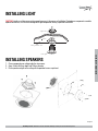
INSTALLING LIGHT ........................................................................................................... 25
INSTALLING SPEAKERS ..................................................................................................... 25
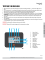
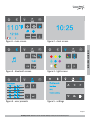
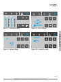
TESTING MACHINE ........................................................................................................... 26
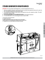
STEAM GENERATOR MAINTENANCE ..................................................................................... 29
TROUBLE SHOOTING ........................................................................................................ 28
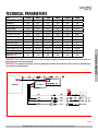
TECHNICAL PARAMETERS .................................................................................................. 31
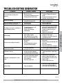
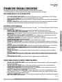
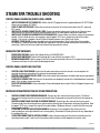
STEAM SPA TROUBLE SHOOTING ........................................................................................ 32
IMPORTANT!
PRIOR TO INSTALLATION, LET WATER RUN THROUGH THE WATER PIPE TO CLEAN ANY POSSIBLE
DEBRIS BEFORE CONNECTING THE GENERATOR.

SteamSpa PHONE: 800-856-0172 FAX: 866-560-1060 http://steamspa.com [email protected]
Page 6
INSTALLATION & USER GUIDE
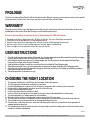
PROLOGUE
Thank You for choosing SteamSpa for health, beauty and relaxation. Now you can enjoy your own private sanctuary in the comfort
of your own home. Let your stress melt away as you relax in your state of the art Steam Room.
WARRANTY
SteamSpa warrants that this steam bath generator unit will be free from manufacturer defects and malfunctions. For terms and
condition please refer to latest SteamSpa Warranty at www.SteamSpa.com/warranty.
Please be advised failure to comply with any of the following will VOID the warranty.
1. Generator and Use are registered within 90 days of delivery. See www.SteamSpa.com/register.
2. Installation must be performed by a licensed professional.
3. A quick release & pressure reducing valve must be used for reliable periotic maintenance.
4. An inline water filter must be installed to prevent mineral deposit and build up.
5. Filter cartridge must be replaced no later than every 6 months.
USER INSTRUCTIONS
1. Check for visible damages upon delivery of Generator. Any damages to packaging should be reported immediately to shipping
company delivery representative and SteamSpa’s Customer Service Dept.
2. Check model and accessories are correct, including voltage input. Any discrepancies are to be reported to SteamSpa’s
Customer Service Dept. within 48 hours of delivery.
3. Read installation instructions in detail for a secure and effective installation of SteamSpa generators.
4. SteamSpa recommends the use of a licensed plumber and electrician for proper installation of SteamSpa generators.
5. SteamSpa shall not be responsible for product damage or malfunction caused by self-installation or installation procedures
which do not comply with user manual.
6. SteamSpa generators are for indoor use only.
CHOOSING THE RIGHT LOCATION
1. The generator should be less than 25ft from the steam room for best performance.
2. The steam generator should not be installed in the steam room
3. Do not install outdoor or in any places that will influence the performance of the machine by the environment.
4. Do not install in a frigid location or any places where the water will freeze.
5. Do not install near flammable chemicals.
6. Install in a dry place where the ventilation is good.
7. Install an exhaust fan outside of the steam room for the excess steam to be expelled from the shower room.
8. The steam generator has a hanging groove for wall installations..
9. Both sides and the top of the steam generator need to reserve at least 12 inches space.
10. The area where the machine is installed must be easily cleaned up and convenient for the disassembly of the machine.
11. The installation area must be convenient for the steam generator draining system.
12. The steam tube, safety valve, drain valve, water tube and steam outlet remain very heated after the steam generator has
stopped working for some time.
13. The controller panel should be installed away from the steam head to avoid false readings,please read the instructions for the
controller’s installation and operation.

SteamSpa PHONE: 800-856-0172 FAX: 866-560-1060 http://steamspa.com [email protected]
Page 7
INSTALLATION & USER GUIDE
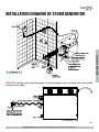
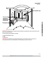
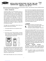
INSTALLATION DRAWING OF STEAM GENERATOR
ATTENTION! The drawing is only for explanation purposes. As for practical design of steam room, please consult with a qualified
designer, architect or builder.

SteamSpa PHONE: 800-856-0172 FAX: 866-560-1060 http://steamspa.com [email protected]
Page 8
INSTALLATION & USER GUIDE
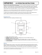
ATTENTION! The drawing is only for explanation purposes, please consult with a qualified designer, architect or builder.
IMPORTANT! All pipe connections should have unions and adapters for easy disconnect.
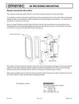
ATTENTION! Proper installation is a critical requirement per the SteamSpa Warranty terms and conditions. A licensed
professional must be used to ensure proper installation. A quick release system, pressure reducing valve, inline water filter and
regular maintenance are required.
WARNING! Water pressure should
reduced to 15 PSI for proper generator
operation and to avoid leaks or crack in
water filter. Installation must be done in
the following order:
1. Pressure Reducing Valve
*
2. Water Filter
3. Quick Shut-off Valve
*
4. Steel Braided Flex-Hose*
* Available with the Quick Connect Install Kit
1
1
2
3
4
Water Supply Line
Steam Generator
2
3
4

SteamSpa PHONE: 800-856-0172 FAX: 866-560-1060 http://steamspa.com [email protected]
Page 9
INSTALLATION & USER GUIDE
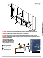
ATTENTION! The illustration is just an example; the practical installation must comply with the nation’s electrical criteria, and be
done by a professional electrician.
The steam generator maybe installed in these location.
1. In closet located behind the shower.
2. In Attic
3. In basement etc.
ATTENTION! If the installation of the steam generator will be more then 10 to 15 feet away from the steam room. It is
recommended to increase the size of the generator 1 or 2 kilowatts higher to increase the steam flow.
110

SteamSpa PHONE: 800-856-0172 FAX: 866-560-1060 http://steamspa.com [email protected]
Page 10
INSTALLATION & USER GUIDE
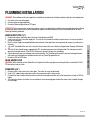
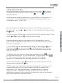
PLUMBING INSTALLATION
WARNING! The installation of all water supply lines should be in accordance to all national and local codes by a licensed plumber.
1. Use unions when connecting pipes.
2. Use brass pipes or copper pipe only.
3. Do not use black and galvanized or PVC pipes.
ATTENTION! Please ensure a quick connect and release system in employed when installing steam generator to plumbing. Doing
so will ensure quick and easy access to the generator for regular care and maintenance and is a critical condition for an active
SteamSpa Warranty protection.
WATER SUPPLY PIPE (1/2’’)
1. Connect hot water or cold water pipes. However it should not exceed 160F.
2. Install a shut off valve in the water supply line. The shut off valve should be installed in a place where it is easily accessible in
case of an emergency.
3. Flush the water supply line completely before connecting the water pipe to the steam generator, to remove any sediments in
the water.
4. Use a 3/8” steel braided flex hose with a shut off valve to connect the main waterline to the generator. See page 5 illustration
1.2.
5. The shut off valve should be open approximately 25% to reduce water pressure to the generator. The water pressure to the
generator should be between 15 to 20 PSIG if necessary, decrease the pressure accordingly.
6. A hydro pneumatic pressure reducing valve must be installed. The SteamSpa quick release & pressure reducing kit comes
with a pressure reducing device calibrated to work with any SteamSpa generator unit.
7. Do not use PEX or PVC tubing.
INLINE WATER FILTER
WARNING! When installing an Inline Water Filter it is imperative that the water pressure entering the filter is reduced to 15 to 20
PSI to avoid any leaks or cracks.
STEAM PIPE (3/4’’)
1. Do not install any stop valves in the steam pipes. The steam can never be obstructed.
2. Install a 3/4” copper or brass pipe between the steam generator and the steam nozzle.
3. If needed, the heat insulation material used to insulate the steam pipe should be resistant to temperatures as high as 240F or
higher.
4. The shorter the distance, the better. Use curved elbows when connecting pipes to allow the steam to flow smoothly through
the steam pipe.

SteamSpa PHONE: 800-856-0172 FAX: 866-560-1060 http://steamspa.com [email protected]
Page 11
INSTALLATION & USER GUIDE
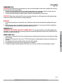
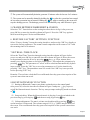
STEAM HEAD (3/4’’)
ATTENTION! Steam Head and the steam outlet gets very hot, try to avoid installing the steam head in a position which will easily
come into contact with the person bathing.
1. Install the steam head approximately 12 inches above the ground floor. If the steam room material is acrylic or non-heat-
resistant sheet, please consult with material manufacturer about steam room applications.
2. The steam head outlet should be installed face down. To prevent scalding bather with steam or water.
ATTENTION! Tighten steam head by hand. Do not use a spanner or other tools, use a little soap water and soft sponge to wipe,
and do not use erosive chemical solutions or crude cleaning tools.
IMPORTANT!
1. Please consult manufacturer of materials like acrylic, fiber glass or other anti-heat sheet about the installation of the steam
head.
2. In the entire steam room, it is required that steam does not leak out. The pipes, its accessories and the holes should be air
proof by applying sealant so that no steam will enter the holes in the wall.
DRAINPIPE (1/2’’)
ACCORDING TO THE NATIONAL AND LOCAL PLUMBING CODES: The steam generator drain valve should be equipped with
a drainpipe. The steam generator drains the water by gravity.Check local code requirements for drain valves. Do not connect the
safety valve or steam line to drain line.
SAFETY VALVE (3/4’’)
1. Safety valve is an automatic system that is actuated by pressure in order to prevent steam pressure increasing in the interior
of the generator .
2. The pressure limit range of the safety valve is 15 PSIG and the pressure will begin to decrease if pressure should come over
this value.
3. If it is allowed by local codes, provide the safety valve with exterior drainpipe.
4. Do not dismantle the pressure relief valve while generator is in operation.
5. To maintain the proper automatic operation of the safety valve, make sure the safety valve connection pipe is smooth.

SteamSpa PHONE: 800-856-0172 FAX: 866-560-1060 http://steamspa.com [email protected]
Page 12
INSTALLATION & USER GUIDE
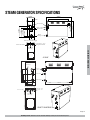
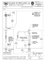
STEAM GENERATOR SPECIFICATIONS
4.5kW
6kW/7.5kW/9kW
Safet y val ve
St eam outlet
Wat er inlet
Wat er
drainage
20 6mm
18 8mm
15 1mm
32mm
43mm
142mm
266mm
302mm
395mm
Fuse for wire power supply
Power wire hole
C on tr o ll e r w ir e
and light wi re hol e
304mm
400mm
16 0m m
10 0m m
30 mm
30mm
18 0mm
26 0m m
37 0mm
Steam outlet
S a f e t y
valve
Water inlet
Water drainage
Fus e for w ire pow er supply
Pow er wire hole
C o n tro ller wire
an d lig h t wir e
hole
Fuse for wire
power supply
Fuse for wire
power supply
62mm
72mm

SteamSpa PHONE: 800-856-0172 FAX: 866-560-1060 http://steamspa.com [email protected]
Page 13
INSTALLATION & USER GUIDE
ATTENTION! To facilitate maintenance, keep the steam engine clean. If the information provided is limited, do not operate on the
pipeline and electric equipment arbitrarily as shown in the figure for proportion.
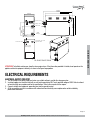
ELECTRICAL REQUIREMENTS
ELECTRICAL SUPPLY CIRCUITRY
1. Test the voltage of the power supply and make sure suitable voltage is used for the steam generator.
2. Insulated copper wire should be used with an anti-heat temperature of 90 C and a specified voltage of 300V. Refer to national
or local electricity consumption code for the specifications. Refer to the ammeter for the ampere.
3. Connect suitably sized equipment grounding wire into the ground terminal.
4. All the connections must be in accordance with national and local electricity consumption codes and be installed by
professional electricians.
10.5k W/12kW/15k W
535mm
435mm
Steam outlet
Safety valve
Water inlet
Water
dr ainage
Fuse for wire power supply
Power wire hole
Controller wire and
light wir e hole
35 0mm
38 5mm
234mm
273mm
183mm
34mm
Fuse for wire
power supply

SteamSpa PHONE: 800-856-0172 FAX: 866-560-1060 http://steamspa.com [email protected]
Page 14
INSTALLATION & USER GUIDE
The data provided above is for 240V single-phased motors. Install an independent circuit breaker between supply line and steam
generator. Install a power disconnect within sight of steam generator to cut-off power when not in use.
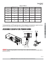
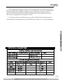
ASSEMBLY GRAPH FOR POWER WIRE
ATTENTION! To avoid damage to the equipment, do not connect electric current directly to heating elements.
WARNING! This graph is for explanation only. For actual installation, refer to national and local electricity consumption codes by
professional electricians.
Ampere Meter
Ty p e Powe r KW
B-600
B-750
6
7.5
9
240V
240V
240V
25
32
38
10
8
8
150
225
300
Ap pli cab l e sp ace o f
the room (cu.Ft . *)
E l e c t r i c i t y
supply (1PH)
E l e c t r i c
current (A)
Speci ficat i ons for
power wire (AWG)
10.5
240V 44 6400
12
240V
50
6
450
B-900
B-1050
B-1200
B-450
4.5 240V
19
12
90
240V
( 2 4 0 V ~ 1PH)
Power co nnectio n term inal
( 4 . 5 - 1 2kW )
L1
Ground Hot
L2
L1 L2
L2
L1

SteamSpa PHONE: 800-856-0172 FAX: 866-560-1060 http://steamspa.com [email protected]
Page 15
INSTALLATION & USER GUIDE
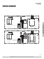
WIRING DIAGRAM
J1-1
J2-1
J2-2
J1-2
J1J2
S S
L1 G
B-600
Su p p ly
Red
Black
R e d
B l a c k
Bl ack
L2
Red
Red
T o C ont rol P ane l
Fill water valve
Drain water valve
Te rm i na l B l oc k
Ye l l ow / G re e n
R e d
B l a c k
R e d
Black
White
B l a c k
Yel low
R e d
B l a c k
Red
Red
Red
Red
Wa te r L e ve l Se nsor
Red ( S h o r t P i n )
Bl ack ( L o n g P i n )
Yel l o w ( M i d d l e P i n )
T o C ont rol P ane l
Fill water valve
Drai n water valve
Te rm i na l B l oc k
J1-1
J2-1
J3-1
J3-2
J2-2
J1-2
J1J2J3
S S
G
Ye l l ow / G re e n
R e d
B l a c k
Red
Black
White
Black
Yellow
R e d
B l a c k
Red
Red
Red
Red
Su p p ly
R e d
B l a c k
RedBlack
L1L2
Wa te r L e ve l Se nsor
Red ( S h o r t P i n )
Bl ack ( L o n g P i n )
Yel l o w ( M i d d l e P i n )
Red
Red
Red
B-750 B-900
Red
Red
Black
Black
Black
Black
Black
Blac k
Red
Bl ack
J1-1
J1-2
J1
S S
L1 G
B-450
Su p p ly
Red
R e d
B l a c k
Bl ack
L2
Red
T o C ont rol P ane l
Fill water valve
Drain water valve
Te rm i na l B l oc k
Ye l l ow / G re e n
R e d
B l a c k
R e d
Black
White
B l a c k
Yellow
R e d
B l a c k
Red
Red
Red
Red
Wa te r L e ve l Se nsor
Red ( S h o r t P i n )
Bl ack ( L o n g P i n )
Yel l o w ( M i d d l e P i n )
Bla ck

SteamSpa PHONE: 800-856-0172 FAX: 866-560-1060 http://steamspa.com [email protected]
Page 16
INSTALLATION & USER GUIDE
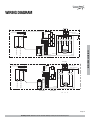
WIRING DIAGRAM
J1-1
J2-1
J2-2
J1-2
J1J2
S S
L1 G
B-600
Su p p ly
Red
Black
R e d
B l a c k
Bl ack
L2
Red
Red
T o C ont rol P ane l
Fill water valve
Drain water valve
Te rm i na l B l oc k
Ye l l ow / G re e n
R e d
B l a c k
R e d
Black
White
B l a c k
Yel low
R e d
B l a c k
Red
Red
Red
Red
Wa te r L e ve l Se nsor
Red ( S h o r t P i n )
Bl ack ( L o n g P i n )
Yel l o w ( M i d d l e P i n )
T o C ont rol P ane l
Fill water valve
Drai n water valve
Te rm i na l B l oc k
J1-1
J2-1
J3-1
J3-2
J2-2
J1-2
J1J2J3
S S
G
Ye l l ow / G re e n
R e d
B l a c k
Red
Black
White
Black
Yellow
R e d
B l a c k
Red
Red
Red
Red
Su p p ly
R e d
B l a c k
RedBlack
L1L2
Wa te r L e ve l Se nsor
Red ( S h o r t P i n )
Bl ack ( L o n g P i n )
Yel l o w ( M i d d l e P i n )
Red
Red
Red
B-750 B-900
Red
Red
Black
Black
Black
Black
Black
Blac k
Red
Bl ack
J1-1
J1-2
J1
S S
L1 G
B-450
Su p p ly
Red
R e d
B l a c k
Bl ack
L2
Red
T o C ont rol P ane l
Fill water valve
Drain water valve
Te rm i na l B l oc k
Ye l l ow / G re e n
R e d
B l a c k
R e d
Black
White
B l a c k
Yellow
R e d
B l a c k
Red
Red
Red
Red
Wa te r L e ve l Se nsor
Red ( S h o r t P i n )
Bl ack ( L o n g P i n )
Yel l o w ( M i d d l e P i n )
Bla ck
T o C ont rol P ane l
Fill water valve
Drain water valve
Te r m i na l B l oc k
J1-1
J2-1
J2-2
J1-2
J1J2
S S
G
Ye l l ow / G re e n
R e d
B l a c k
R e d
Black
White
B l a c k
Yellow
R e d
B l a c k
Red
Red
Red
Red
Su p p ly
R e d
B l a c k
Black
L1
Wa te r L e ve l Se nsor
Red ( S h o r t P i n )
Bl ack ( L o n g P i n )
Yel l o w ( M i d d l e P i n )
B-1200
L2
Red
Bl ack
Red
Red
Black
Black
Red
B-1050
T o C ont rol P ane l
Fill water valve
Drain water valve
Te r mi na l B l oc k
J1-1
J2-1
J2-2
J1-2
J1J2
S S
G
Ye l l ow / G re e n
R e d
B l a c k
R e d
Black
White
B l a c k
Yellow
R e d
B l a c k
Red
Red
Red
Red
R e d
B l a c k
Black
L1
Wa te r L e ve l Se nsor
Red ( S h o r t P i n )
Bl ack ( L o n g P i n )
Yel l o w ( M i d d l e P i n )
L2
Red
Bl ack
Red
Red
Black
Bl ack
Red
J3-1
Bl ack Bl ack
J3-2
Red Red
B-1500

SteamSpa PHONE: 800-856-0172 FAX: 866-560-1060 http://steamspa.com [email protected]
Page 17
INSTALLATION & USER GUIDE
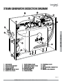
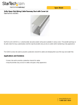
STEAM GENERATOR DISSECTION DIAGRAM
1
2
3
4
6
5
7
13
14
12
9
11
8
10
15
17
16
1. ENCLOSURE
2. INSULATION BRACKET
3. CIRCUIT BOARD
4. STEAM OUTLET
5. PRESSURE RELIEF VALVE
6. WATER FILL VALVE
7. WATER DRAIN VALVE
8. SUBSIDIARY WATER TANK
9. MAIN WATER TANK
10. HEATING ELEMENT
11. 221 F HI-LIMIT
12. TRANSFORMER
13. TERMINAL BLOCK
14. FUSE
15. GROUND WIRE CONNECTOR
16. RELAY
17. WATER LEVEL SENSOR

SteamSpa PHONE: 800-856-0172 FAX: 866-560-1060 http://steamspa.com [email protected]
Page 18
INSTALLATION & USER GUIDE
CARE & USE FOR THE CONTROL PANEL
1. Use soft cloth with a little soap water to clean the control panel.
2. Do not use crude cleaning tools.
3. If the decorating facade is damaged, contact service electrician to change it.
Do not install any SteamSpa controls without reading and understanding the SteamSpa generator Installation and Instruction
manual. Failure to read and understand these instructions will result in inoperative control, generator, hazardous overheating, and/
or inadequate heating of the steam room.
Do not route control wiring inside or close to power lines conduit, hot water or steam piping. Doing so may result in an inoperative
control, generator, and/or hazardous installation.
Do not install SteamSpa controls with other than SteamSpa compatible steam generators. Doing so may result in possible
generator damage or inoperative installation.
Single Control Panel with Temperature sensor must be installed inside bathing area 5 feet above floor. Do not install Control
directly above Steam Head or below shower head but rather in the seating area on a vertical wall. Doing so may result in improper
temperature reading and/or inoperable control.
Turn power to the steam generator off before connecting the control to the generator. Failure to turn the power off generator prior
to connecting controls will result in an inoperable control.
Discontinue use of the steam generator or control if the steam generator is damaged. Continue to do so may result in an
inoperative or hazardous installation.
CONTROLLER BOX CONTENT
• One (1) SteamSpa Black Control Console
• Two (2) Chroma Color Light
• One (1) LED White Light
• Two (2) Shower Speakers with Grills
• One (1) Rim Extension
• One (1) Control Box
• Four (4) Extension Cables
• User guide

SteamSpa PHONE: 800-856-0172 FAX: 866-560-1060 http://steamspa.com [email protected]
Page 19
INSTALLATION & USER GUIDE
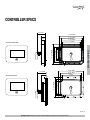
1. 7
WITH EXTENSION RIM
NO EXTENSION RIM
0
0. 9 2 I NCH
I NCH
0.8 9 I NCH
4. 37 I NCH
4. 78
I
NCH
4. 41
I
NCH
4 I NCH
3. 20 I NCH
3. 10 I NCH
2. 07 I NCH
5. 54
I
NCH
1. 70 I NCH
0.9 2 INCH
0.31 INCH
5. 54 I NCH
4. 41 I NCH
4 I NCH
4. 37 I NCH
3. 20 I NCH
3. 10 I NCH
CONTROLLER SPECS

SteamSpa PHONE: 800-856-0172 FAX: 866-560-1060 http://steamspa.com [email protected]
Page 20
INSTALLATION & USER GUIDE
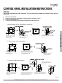
CONTROL PANEL INSTALLATION INSTRUCTIONS
STEP ONE
Determine the installation location of the control panel. The master control panel is designed to be installed in the steam room only,
please install:
1. 4-5 feet from the ground.
2. Keep away from the steam head and do not expose under the direct spray of steam.
3. Install in the perpendicular wall.
4. The position of installation should facilitate easy operation and convenient wiring.
Create the hole for control
box. Make it 47 to 50 inches
from the ground.
Create the hole for mounting
plate. Make it 47 to 50 inches
from the ground.
Open a hole as shown above.
Make it 47 to 50 inches from
the ground.
A. Recess mount onto the wall using the control box.
B. Recess mount with mounting plate.
C. Using the double-sided adhesive.
Place control box into the
hole. Insert screws to hold
control box in place.
Fix the control panel to the control
box. Add a bead of silicone around
the edge to seal.
Fix the control panel to
the mounting plate.
Apply the sticker to the back
of the controller. And press
onto the wall.
Apply the double sided tape.
Apply the double sided tape to the
back. And add a bead of silicone
around the inner lip to seal.
Apply the double sided tape to the
back. And add a bead of silicone
around the inner lip to seal.
Make sure to add the extension rim
behind the control panel’s edge.
1.25”
.4”
4.5”
3.3”
4.72”
3.5”
2.95”
.15”
Page is loading ...
Page is loading ...
Page is loading ...
Page is loading ...
Page is loading ...
Page is loading ...
Page is loading ...
Page is loading ...
Page is loading ...
Page is loading ...
Page is loading ...
Page is loading ...
Page is loading ...
Page is loading ...
Page is loading ...
Page is loading ...
-
 1
1
-
 2
2
-
 3
3
-
 4
4
-
 5
5
-
 6
6
-
 7
7
-
 8
8
-
 9
9
-
 10
10
-
 11
11
-
 12
12
-
 13
13
-
 14
14
-
 15
15
-
 16
16
-
 17
17
-
 18
18
-
 19
19
-
 20
20
-
 21
21
-
 22
22
-
 23
23
-
 24
24
-
 25
25
-
 26
26
-
 27
27
-
 28
28
-
 29
29
-
 30
30
-
 31
31
-
 32
32
-
 33
33
-
 34
34
-
 35
35
-
 36
36


SteamSpa BKT450CH-A Installation guide
- Category
- Sanitary ware
- Type
- Installation guide
- This manual is also suitable for
Ask a question and I''ll find the answer in the document
Finding information in a document is now easier with AI
Related papers
-
SteamSpa RYT450CH Installation guide
-
-
SteamSpa RYT1050OB-A User manual
-
 SteamSpa OAT900CH Installation guide
-
 SteamSpa D-450 Installation guide
-
SteamSpa RYT450CH User manual
-
-
SteamSpa INT450BN Installation guide
-


Other documents
-
Redring RIWH6 Inline Instantaneous Water Heater Product information
-
 RELAX-A-MIST JR-2 Installation guide
-
Ariel WS-802L Installation guide
-
 Amerec AX Control "A3" Operating instructions
-
HygroMatik C-DS User manual
-
 Amerec AX Control "A6" Operating instructions
-
Adcraft CTS-1800W User manual
-
Jacuzzi SteamPro User manual
-
 T & S Brass & Bronze Works BL-5705-10 Datasheet
-
 StarTech.com AD3X3 Datasheet


