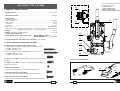
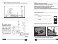
Cembre LD-2EY is a powerful electric shear designed for cutting copper and aluminum cables and conductors. It features a compact and lightweight design, making it easy to handle and transport. The LD-2EY has a cutting capacity of up to 70 mm² for copper cables and 50 mm² for aluminum cables, making it suitable for a wide range of applications.
Cembre LD-2EY is a powerful electric shear designed for cutting copper and aluminum cables and conductors. It features a compact and lightweight design, making it easy to handle and transport. The LD-2EY has a cutting capacity of up to 70 mm² for copper cables and 50 mm² for aluminum cables, making it suitable for a wide range of applications.


-
 1
1
-
 2
2
-
 3
3
-
 4
4
-
 5
5
-
 6
6
-
 7
7
-
 8
8
-
 9
9
-
 10
10
-
 11
11
-
 12
12
-
 13
13
-
 14
14
-
 15
15
-
 16
16
-
 17
17
-
 18
18
-
 19
19
-
 20
20


Cembre LD-2EY is a powerful electric shear designed for cutting copper and aluminum cables and conductors. It features a compact and lightweight design, making it easy to handle and transport. The LD-2EY has a cutting capacity of up to 70 mm² for copper cables and 50 mm² for aluminum cables, making it suitable for a wide range of applications.
Ask a question and I''ll find the answer in the document
Finding information in a document is now easier with AI
Related papers
-
Cembre LD-1P-ECO User manual
-
Cembre LD-41P User manual
-
-
Cembre LD-2E User manual
-
-
-
Cembre ANE-U User manual
-
Cembre CP1120-W-1000-KV User manual
-
-
Other documents
-
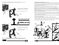
AUKEY 2021 Upgraded AUKEY Phone Car Holder User guide
-
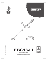 Erbauer EBC18-Li Original Instructions Manual
-
Full Boar FBMD-1242 User manual
-
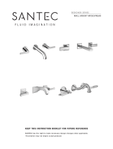 Santec 3429AT91-TM User manual
-
Euroboor RAIL.40S User manual
-
Atdec AW-FB Installation guide
-
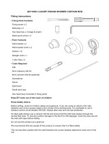 Croydex AD116541YW Installation guide
-
Milltronics VM4325xp (8200 Control) Instruction Handbook
-
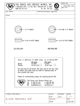 T & S Brass & Bronze Works 000764-20 Datasheet
-
 Croydex AD116441YW Installation guide


