Page is loading ...

INSTALLATION INSTRUCTIONS
MRC-816 MULTI-ROOM CONTROLLER

SAFETY INSTRUCTIONS
Read all of these instructions before operating and save instructions for later use.
1. Read Instructions – All the safety and operating instructions should be read before the appliance is operated.
2. Retain Instructions – The safety and operating instructions should be retained for future reference.
3. Heed Warnings – All warnings on the appliance and in the instructions should be adhered to.
4. Follow Instructions – All operating and use instructions should be followed.
5. Water and Moisture – The appliance should not be used near water – for example, near a bathtub, washbowl, kitchen sink, laundry
tub, in a wet basement or near a swimming pool.
6. Carts and Stands – The appliance should be used only with a cart or stand that is recommended by the manufacturer. An appliance
and cart combination should be moved with care. Quick stops, excessive force, and uneven surfaces may cause the appliance and
cart combination to overturn.
7. Wall or Ceiling Mounting – The appliance should be mounted to a wall or ceiling only as recommended by the manufacturer.
8. Ventilation – The appliance should be situated so that its location or position does not interfere with its proper ventilation. For
example, the appliance should not be situated on a bed, sofa, rug, or similar surface that may block the ventilation openings; or,
placed in a built-in installation, such as a bookcase or cabinet that may impede the flow of air through the ventilation openings.
9. Heat – The appliance should be situated away from heat sources such as radiators, heat registers, stoves, or other appliances
(including amplifiers) that produce heat.
10. Power Sources – The appliance should be connected to a power supply only of the type described in the operating instructions or as
marked on the appliance.
11. Grounding or Polarization – Precautions should be taken so that the grounding or polarization means of an appliance is not defeated.
12. Power-Cord Protection – Power-supply cords should be routed so that they are not likely to be walked on or pinched by items placed
upon or against them, paying particular attention to cords at plugs, convenience receptacles, and at the point where they exit from the
appliance.
13. Cleaning – The appliance should be cleaned only as recommended by the manufacturer.
14. Power Lines – An outdoor antenna should be located away from the power lines.
15. Nonuse Periods – The power cord of the appliance should be unplugged from the outlet when left unused for a long period of time.
16. Object and Liquid Entry – Care should be taken so that objects do not fall and liquids are not spilled into the enclosure through
openings.
17. Damage Requiring Service – The appliance should be serviced by qualified service personnel when:
◦ The power-supply cord or the plug has been damage; or
◦ The appliance has been exposed to rain; or
◦ Objects have fallen, or liquid has spilled into the appliance; or
◦ The appliance does not appear to operate normally or exhibits a marked change in performance; or
◦ The appliance has been dropped or the enclosure damaged.
18. Servicing – The user should not attempt to service the appliance beyond that described in the operating instructions. All other
servicing should be referred to qualified service personnel.
Page 2 of 21

TABLE OF CONTENTS
SAFETY INSTRUCTIONS.........................................................................................................................2
INTRODUCTION.......................................................................................................................................4
SYSTEM OVERVIEW................................................................................................................................5
MRC-816 Controller................................................................................................................................5
Rear Panel................................................................................................................................................6
TP-2 touch panel......................................................................................................................................7
DESIGNING AND INSTALLING A MRC-816 SYSTEM........................................................................9
System Design.........................................................................................................................................9
Head End Considerations.........................................................................................................................9
Zone Considerations................................................................................................................................9
INSTALLATION.........................................................................................................................................9
Controller Location..................................................................................................................................9
Ventilation................................................................................................................................................9
Touch Panel Location & Mounting..........................................................................................................9
INSTALLING WIRING..............................................................................................................................9
Touch Panel wiring................................................................................................................................10
Speaker wiring.......................................................................................................................................10
Mute.......................................................................................................................................................10
RS-232...................................................................................................................................................11
Audio Page.............................................................................................................................................11
MAKING CONNECTIONS......................................................................................................................11
HEAD END CONNECTIONS..............................................................................................................11
ZONE CONNECTIONS........................................................................................................................12
SYSTEM EXPANSION TO 16 ZONES...................................................................................................13
EXPANDED SYSTEMS.......................................................................................................................14
SYSTEM POWER UP...............................................................................................................................15
SYSTEM PROGRAMMING....................................................................................................................15
FIRMWARE UPDATES............................................................................................................................16
Upgrading the MRC-816 Controller......................................................................................................16
Upgrading the MRC-816 Touch Panels.................................................................................................16
RS-232 PROTOCOL.................................................................................................................................16
TROUBLESHOOTING.............................................................................................................................18
SPECIFICATIONS....................................................................................................................................19
WARRANTY.............................................................................................................................................20
Page 3 of 21

NEXUS AUDIO SYSTEMS
MRC-816 INSTALLATION INSTRUCTIONS
INTRODUCTION
Welcome to Nexus Audio Systems and congratulations on your purchase of the MRC-816 Multi-Zone Controller.
The MRC-816 utilizes standard CAT-5e cabling for touch panel connections and standard speaker wire for the
speaker connections. All aspects of the system setup are accomplished via a convenient web interface similar to
what would be seen on a soho router. Just connect the MRC-816 to the home network, and navigate with a web
browser to http://nexus816
The MRC-816 supports eight independently operated zones and infrared (IR) control of six external line level
audio source components. The MRC-816 also features a built-in AM/FM Tuner with twenty channel presets.
Each zone 1-6 features a 20 watts per channel stereo amplifier. Zones 7-8 are line level output for use with Nexus
zone amplifiers. Each of the routed source IR outputs can be used to control legacy home electronics such as CD
players. The unit includes an RS-232 Port that allows the MRC-816 to be easily integrated with other home
automation control systems. A mute function that can integrate with a doorbell or telephone system to ensure no
important call or visitor is ever missed, and audio paging for whole-house audio announcements. The system is
expandable to 16 zones using two MRC-816 Controllers.
The MRC-816 touch panels provide simple, intuitive control of zone power, source selection, source control,
volume, treble and bass and tuner functions. The touch panel LCD indicates zone status, source selection,
volume as well as tuner frequency and preset. Zone names and source names are configurable in the MRC-816
web interface and are displayed on the touch panel LCD. The touch panel features a built-in infrared receiver that
can be used with third party manufacturer supplied remotes to pass IR data back to the remotely located source
equipment.
The Zone Sharing feature allows up to three zones to be linked together for ease of use in common areas that
would typically have the same source selected and playing. Zone Sharing includes two modes. One links the
zones for power, source and volume, the other has the same source selected in all three zones, but each zone
retains independent power and volume control.
Thank you for your support.
Page 4 of 21

SYSTEM OVERVIEW
Eight Zones (expandable to sixteen using two MRC-816 controllers).
20W/channel into 8 ohms, all zones driven.
Up to 6 stereo audio source inputs.
Fixed/variable line level outputs.
Mute input with 12V DC trigger.
Audio page input with dry contact trigger.
Six routed source IR outputs.
RS232 serial control port.
USB connector for firmware updates via thumb drive.
Eight RJ45 touch panel ports.
Six Molex Speaker Connectors.
Built in AM/FM tuner with twenty presets.
LAN port for web end setup.
Dimensions: 17”W x 3.75H x 14”D
Designed and manufactured in Canada.
FEATURES
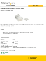
Figure 1. MRC-816 Controller Front Panel
MRC-816 Controller
Front Panel
1. IR Learning Eye – IR sensor used for programming IR commands.
2. Zone Status LEDs – 8 LEDs illuminate blue to indicate powered zones.
Page 5 of 21

FEATURES (contd.)
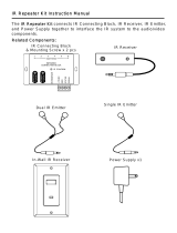
Figure 2a. MRC-816 Controller Rear Panel
Rear Panel
1. Touch Panel Ports – Eight RJ45 jacks, connect to MRC-816 touch panels via CAT-5 Cable. Zone control for
power, source selection, tuning, tone controls, etc are communicated on these connections.
2. Audio Inputs – Six stereo pair RCA jacks connect to the left & right line level audio outputs of up to six
external source components using standard RCA patch cords.
3. IR – Six 3.5mm mini jacks output routed IR commands to their specific corresponding source components.
Polarity: Tip = signal; sleeve = ground.
4. Nexlink – One RJ11 jack connects to the Nexlink jack on a second MRC-816 for system expansion to
sixteen zones.
5. Audio Page – One, four-pin terminal adapts to one of the included Molex connectors to switch all zones
configured for audio page in the controller setup to the audio page source. Pins 1-2 are page audio in. Pins 3-
4 are a dry contact input (shorting pins 3-4 activates page).
6. Mute – One 2.1mm coaxial jack mutes audio in selected zones as configured in the controller setup when
12VDC is present. Polarity: Pin = +12VDC; Sleeve = GND.
7. AM/FM Antenna – One female ‘F’ type terminal for connecting the included AM/FM wire antenna.
8. AC Power – Standard IEC 3-conductor AC line cord receptacle.
9. FN button – Used when performing firmware updates to the system.
10. LAN – Connect to home network router or switch.
11. Indicator LED – May flash at various rates for indication of certain activities.
12. RS-232 – One, DB9 female connector provides two-way RS-232 communication with home automation
systems. Pinout: Pin 2 = Tx; Pin 3 = Rx; Pin 5 = Ground.
13. USB Flash Drive – One, USB 2.0 Port connects to a USB flash drive for installing firmware updates.
14. Zone Line Level Outputs - Stereo pair RCA jacks connect to the left & right line level audio inputs on an
external audio amplifier.
15. Speaker terminals – Zones one to six have a built in 20W/ch stereo amplifiers. Connect speakers to utilize
these amplifiers.
16. Trigger outputs – When the zone is turned on, a DC voltage is supplied from the trigger output. This can be
used to remotely power on an external amplifier.
Page 6 of 21

TP-2 touch panel
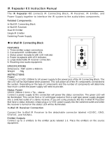
Figure 3. TP-2 Touch Panel (trim plate removed)
1. J-Box Screw Holes – Four slots adapt to the mounting holes on a standard 2-gang J-Box when wall
mounting the touch panel.
2. Touch Panel Trim Plate Tab Slots – Four slots lock the touch panel trim plate.
3. Touch Panel LCD – Touch activated. Displays zone status for: Source, Volume, Zone Name, Tuner
Frequency and Preset Number. Also displays touch panel Menu for: Tuner Preset programming, Tone
Controls and touch panel Display Contrast.
4. IR Receiver – Allows pass through of consumer remote controls to operate remotely located source
components.
5. Touch Panel Port – Run Cat5e cable from this port to a zone port on the rear of the MRC-816.
Figure 4. TP-2 rear panel
Page 7 of 21

Figure 6. MRC-816 Typical System Connections
Page 8 of 21

DESIGNING AND INSTALLING A MRC-816 SYSTEM
System Design
It is always good to get as much information from the client/user/homeowner as possible when designing a multi-
source, multi-zone system. What sources are they going to use? How many zones will be included in the system?
Some zones may only require speakers for background music, while other zones may include a TV or video
display for movies, sports and news. It’s all part of the same system and planning ahead will insure that the
system does what the user requires…or asks for later.
Head End Considerations
When planning a whole-house system, for either new or existing construction, always try to find the most
convenient location for the system components. Try to find a central location to pull the wire runs to with adequate
space for the components and room to work on them. Certainly not the least important consideration should be
convenience for the user. For service or upgrading components, an equipment closet with rear access to the
components is ideal but not always possible. Consider a pull-out rack mount system if rear access is not possible.
Leave plenty of extra wire to be able to easily remove components should they need service or replacing.
Zone Considerations
Think the system through in terms of how the system will be used. What is the layout of each room? Where will
the speakers go? Where will the touch panels go? Are there going to be any other system components in the
remote zones such as TV’s or video displays? Be sure to pull all required cabling and observe all local building
and electrical codes.
INSTALLATION
Controller Location
The MRC-816 should be located at the main termination of all wire and cable runs. The source components
(Tuner, CD, DVD, SAT, Music Server, etc) should also be installed at this location.
The MRC-816 and source components can be placed on shelves in a wall unit in a media room, or rack mounted
in a standard 19” rack mount system. Always provide convenient access for loading CDs and DVDs. Easy access
for service should also be a consideration.
Ventilation
The MRC-816 must be placed in a location that allows adequate airflow. Leave at least two inches above and
below the unit to allow air to flow freely through the vent holes on the top, bottom and sides. Blocking the vent
holes can inhibit airflow and possibly damage the unit. Removing the feet a placing the unit on a shelf or another
component will inhibit airflow and is not recommended. Additionally, care should be taken to leave plenty of extra
room for wires and cables. Extra wire cramped in around the unit can block side vents and inhibit proper airflow.
Touch Panel Location & Mounting
The MRC-816 touch panels should never be mounted in the same J-box with AC house wiring or any other high
voltage device such as a light switch. Avoid mounting the touch panels in areas with high moisture such as around
sinks, bathtubs, showers or outdoor locations that will be exposed to rain or high humidity. Care should also be
taken to avoid mounting the touch panels in locations that will be exposed to direct sunlight. Sunlight can interfere
with the IR sensors on the touch panels and make it difficult to see the display.
INSTALLING WIRING
One of the most important aspects of system design and installation is the wiring infrastructure. When planning
the wiring infrastructure, always pull extra wire. In new construction, wires can be damaged during construction,
so it is a good idea to use wire with additional conductors in case a nail or staple gets run through a wire.
Additionally, even though the system has been designed and contracted based on extensive interviews with the
homeowner, things change. The homeowner may decide to add music, video and control to additional rooms long
after the walls have been sealed up. In new construction, always pull wire to every room that could ever possibly
Page 9 of 21

be added to the system, so when the homeowner decides to add a room, the wire is already in place. Pull speaker
and control wires for audio and control as well as coax or other appropriate cable (HDMI over CAT-5, etc), for
video distribution, even though the MRC-816 does not switch video and the system will only initially be used for
audio sources. Pull each wire or cable to an appropriate location for touch panels, speakers and video displays.
Terminate with appropriate wall plates or keep a map detailing exactly where the wire runs are terminated in the
walls. Always label the wire runs by room and device to assist in installation and troubleshooting.
Figure 8a. Typical Zone Configuration
Touch Panel wiring:
Pull CAT-5 cables directly from each touch panel location to the MRC-816 Controller location. Terminate with
RJ45 plugs in a pass-through (pin to pin) configuration using the TIA568A Standard pin-out.
CAT-5 RJ45 SIGNAL
White/Green PIN 1 +12V
Green PIN 2 GND
White/Orange PIN 3 Touch panel Data +
Blue PIN 4 IR Data +
White/Blue PIN 5 IR Data -
Orange PIN 6 Touch panel Data -
White/Brown PIN 7 N/C
Brown PIN 8 N/C
Figure 8b. RJ45 TIA568A Standard Pin-out
Speaker wiring:
Pull two conductor wire in home-runs directly from each speaker location to the MRC-816 Controller location. You
will need two 2 conductor runs per zone (stereo pair). You could also use four conductor wire, but will have to split
up the conductors when you get to the speakers. WIRE GAUGE: 16AWG stranded up to 75’; 14AWG stranded up
to 100’. Non-shielded preferred.
NOTE: MAX LOAD: 8 ohms per zone. Do not load more than one pair of 8 ohm speakers per zone. This can
cause the unit to go into protection and may possibly blow fuses.
Mute: Pull two conductor stranded wire from the 12VDC control output on the device that will trigger audio muting
to the MRC-816 Controller location. Terminate with a 2.1mm coaxial plug on the MRC-816 end. POLARITY: TIP =
+12VDC, SLEEVE = GND. WIRE GAUGE: 20AWG up to 500’; 18AWG up to 1000’. MAX VOLTAGE IN: 32VDC.
NOTE: Audio mute function will mute all active zones when 12VDC is present on this input. The menu system
allows you to configure which zone(s) will respond to the mute signal.
Page 10 of 21

RS-232
When controlling the MRC-816 from an external controller such as a whole-house control system, use a DB9M
(male) cable for the MRC-816 RS232 Port and terminate the control system end as appropriate.
NOTE: RS-232 connections should not exceed 50’.
Figure 10. RS-232 Pin-Out
Audio Page
Audio – Pull quality audio cable from the telephone system line audio or paging output to the MRC-816
Controller location.
Control - Pull two conductor stranded wire from the Contact Closure control output on the device that will
trigger Audio Page to the MRC-816 Controller location. The menu system allows you to configure which zones
will respond to the page signal, and at what audio level.
MAKING CONNECTIONS
When connecting source components, or making any connections, be sure that the MRC-816 Controller and all
system devices are turned OFF and disconnected from AC power to prevent electrical shock and to avoid possibly
damaging components.
HEAD END CONNECTIONS
Touch Panels
Terminate each cat5 cable with an RJ45 plug following TIA568A guidelines. Connect the zone cat5 cable to
the appropriate zone port on the MRC-816 rear panel.
Speakers
1. Using 14-16AWG two-conductor stranded wire, strip approximately ¼” of insulation from each conductor.
Twist the strands until tight.
2. Connect the bare wires to the appropriate L+,L-,R-,R+ terminals on one of the included four-position plug-in
connectors. Be sure to maintain proper polarity. Be sure there are no loose strands sticking out that could
cause a short. When screwing down the wire clamps, be sure that the wire insulation does not get caught in
the clamp.
3. Plug the connector into the appropriate zone speaker terminal.
Source Audio
Using quality stereo RCA audio cables with gold connectors for each audio source, connect the left & right
audio outputs of each source to the appropriate left & right audio inputs on the MRC-816 Controller for
Sources 1-6.
IR Emitters
Sources 1-6 – Use industry standard IR emitters for each external source component.
1. Plug each emitter into the appropriate source IR output jack (1-6). (If the CD player is source 1, plug the
emitter for the CD player into emitter jack 1.)
2. Attach the emitter to the front panel of the device being controlled over the IR eye. If the eye is not
obvious, refer to the owner’s manual for that product or shine a small flashlight into the front panel to
locate the eye.
NOTE: IR commands initiated by a MRC-816 will be routed to the emitter for the selected source.
(Commands for Source 1 will only output from emitter 1.) IR pass-through, (IR Commands initiated by the
original equipment remote or a programmed remote) will output from all source emitters.
Page 11 of 21

Mute
Using a properly configured 2.1mm coaxial plug, (see section: Wiring/Mute) connect the 2.1mm coaxial plug
to the Mute jack on the MRC-816 rear panel. Terminate the other end as appropriate and connect to the
12VDC control output terminal on the device used to trigger audio mute. Be sure to maintain proper polarity
from the trigger device control out to the 2.1mm coaxial plug.
RS-232
Using a properly configured DB9 cable (see section: Wiring/RS-232), connect the DB9 male connector to the
RS-232 jack on the MRC-816 rear panel. Appropriately terminate and connect the other end to an appropriate
RS-232 port on the control device. See section: RS-232 Protocol for additional information.
Figure 11. Audio Page Connections
Audio Page
Page Audio
1. Using the audio cable pulled for Audio Page, strip approximately ¼” of insulation from each conductor. Twist
the strands until tight.
2. Connect the bare wires to the two left terminals on one of the included four-position plug-in connectors as
shown in Figure 11. Polarity is not critical. Be sure there are no loose strands sticking out that could cause
a short.
3. Terminate the other end of the audio cable as appropriate and connect to the appropriate audio out on the
paging device.
Page Control
1. Using the two-conductor stranded wire pulled for Audio Page control, strip approximately ¼” of insulation
from each conductor. Twist the strands until tight.
2. Connect the bare wires to the two right terminals on the same four-position plug-in connector used in Step 2
above, as shown in Figure 11. Polarity is not critical. Be sure there are no loose strands sticking out that
could cause a short.
3. Terminate the other end of the control wire as appropriate and connect to the appropriate control out on the
paging device.
4. Plug the connector into the Audio Page Terminal.
ZONE CONNECTIONS (in each room)
Touch Panels
Using CAT-5 cable properly terminated with a RJ45 plug (see section: Wiring/Touch panels) connect the
zone CAT-5 cable to the Touch Panel Controller Connection (RJ45) jack on the touch panel rear panel.
Speakers
1. Using the 14-16AWG two-conductor stranded wire pulled for zone speaker connections, strip approximately
¼” of insulation from each conductor. Twist the strands until tight.
2. Connect the bare wires to the appropriate L+, L-, R-, R+ terminals on the left and right zone speakers. Be
sure to maintain proper polarity. Be sure there are no loose strands sticking out that could cause a short.
Page 12 of 21

SYSTEM EXPANSION TO 16 ZONES
Figure 14. Expanded MRC-816 System
Page 13 of 21

EXPANDED SYSTEMS
Two MRC-816 Controllers can be linked together to expand a MRC-816 system to up to sixteen zones. The
fundamental installation and connections are similar to those on a single controller system with a few minor
changes:
Nexlink Connection
This connection allows communication between the Master and Slave Controllers for zone/system status,
system/source power management, page control, mute control and external common source IR control from the
touch panels or remotes used in the zones connected to the Slave Controller.
Using a RJ11 patch cable configured in a crossover configuration, connect the Nexlink jack on the Master
Controller to the Nexlink jack on the Slave Controller. See Figure 15b for construction of cable.
NOTE: Two linked MRC-816 Controllers must be configured for Master/Slave configuration in the Main Menu
Master /Slave Setup. IR emitter, mute/page and LAN connections are made to the master.
Source Audio
Source audio must be distributed to both the Master and Slave Controller source inputs to have source audio
signals available to all zones.
Use either ‘Y’ adapters or an audio distribution amp to split the line level audio signal from the source outputs
to the source audio inputs on both controllers as shown in Figure 14.
IR Emitters
The IR Emitter are connected to the Master Controller IR Outputs as done in a single controller system. The Slave
Controller will communicate IR control to the Master via the Nexlink connection. See section: Connections/IR
Emitters for additional information.
Speakers
Speakers are connected to the appropriate Master or Slave Zone Speaker Outs as described in section:
Connections/Speakers.
Mute
The Audio Mute control IN is connected to the Master Controller Mute jack as done in a single controller system.
The Master Controller will communicate Audio Mute to the Slave Zones via the Nexlink connection. See section:
Connections/Mute for additional information.
Page Audio
Page Audio – The audio for paging must be distributed to both the Master and Slave Controller Page Audio
inputs to have the Page Audio signals available to all zones.
Using quality audio cable, jump the Page Audio terminals on the Master Controller to the Page Audio
Terminals on the Slave Controller as shown in Figure 15a. Though polarity from the Page Audio Source to
the Master Page Audio IN is not critical, do maintain proper polarity between the Master and Slave Page
Audio Terminals. Be sure there are no loose strands sticking out that can cause shorts.
Page Control - The Page Audio Control IN is connected to the Master Controller Page Audio Control Terminals
as done in a single controller system. The Master Controller will communicate Page control to the Slave via the
Nexlink connection. See section: Connections/Page Audio for additional information.
Page 14 of 21

Figure 15a. Audio Page Connections – Expanded System
Figure 15b. Nexlink cable wiring
SYSTEM POWER UP
After the system wiring is complete, it is time to power up the system. The power switch for the MRC-816 is on the
rear panel of the unit above the power cord. This system is designed to remain powered up continuously. Turn the
power switch on the rear panel to the on position. If you have a 16 zone system using two chassis, then turn on
the other MRC-816 as well.
Touch panel scan – The system is not immediately available for use right after power up, as the touch panel
scanning sequence is initiated first, which checks each port to see if a touch panel is connected, and properly
configured. The eight leds on the front panel will indicate the progress of the touch panel scanning procedure:
Starting with the left most led for zone 1, the led will illuminate momentarily as the port is checked for the
presence of a touch panel. If a touch panel is not found, the led will extinguish, and the next led will illuminate to
check port number two and so on. If a touch panel is detected on a port, the led for that port will remain
illuminated, and scanning will continue with the next port until all eight ports are checked. By observing the
scanning sequence, you can check for the possibility of wiring errors to the touch panels. For example, if you
know that there is a touch panel attached to port 1 (zone 1), but the first led does not remain lit during the
scanning sequence, then there must be a problem in that zone’s wiring. The touch panel scanning sequence
requires about 20 seconds to complete. After this time, all leds go off, and the system is ready for use.
SYSTEM PROGRAMMING
The MRC-816 uses a web end interface for programming all of the system operational parameters. It is essential
that the MRC-816 LAN port is connected to the local area network so that the setup pages may be accessed with
a computer attached to the same network. In an expanded master/slave 16 zone system, connect only the MRC-
816 unit that will be the master, to the network. The setup page for the MRC-816 can be accessed with a PC,
MAC, tablet, or even a cell phone. Open your favorite browser, and navigate to http://nexus816. You may also use
nexus816.local. If for some reason the setup page does not load, please check your connections. You may also
navigate to your local router setup page to discover what ip address the MRC-816 has been assigned, and then
use the ip address directly in your browser. Each setup page in the web interface contains full instructions on how
to program the parameters, and the instructions are not repeated in this manual.
Page 15 of 21
1
1
RJ11
RJ11
Wiring:
Pin1 – NC
Pin2 – Pin5
Pin3 – Pin3
Pin4 – Pin4
Pin5 – Pin2
Pin6 - NC

FIRMWARE UPDATES
From time to time Nexus Audio will release firmware updates for the MRC-816 Controller and/or touch panels.
Sometimes these updates will be improvements to system functionality and sometimes they will be new feature
additions. Updating firmware on the MRC-816 is done with a USB Flash (thumb) Drive.
Updates can be obtained by contacting Nexus Audio Systems Inc.
The file for the MRC-816 Controller (if included) will be named C816B.Vx_xx.hex where x_xx denotes the version
number. Similarly, the file for the touch panels (if included) will be named NEXUSTP1.bin.
The USB flash drive to be used for the upgrade can have other files on it, but if there are a lot of files, the MRC-
816 may take a long time to initialize before the upgrade begins. If the MRC-816 does not initialize or download
the update, delete the extraneous files, or use another flash drive with less files on it.
Upgrading the MRC-816 Controller
1. Unzip, and copy the file C816B_Vx_xx.hex to a USB flash drive in the root directory. NOTE: only have one
version of the file in the root directory. If there are multiple versions, the correct one may not be loaded. If you
want to keep older versions that may be present on the drive, move them to a sub-directory.
2. Turn off the MRC-816.
3. Insert the USB flash drive into the USB port on the MRC-816 Rear Panel.
4. While holding down the FN button beside the power switch, turn on the MRC-816. Then release FN. The
status led beside the LAN port should start to flash.
5. Wait for programming to complete. The status led will begin to rapidly flash as the new software loads. You
will know when programming is complete, as the status led will stop flashing, and the front panel leds will
begin light up as touch panel scanning commences.
6. Remove the USB flash drive.
7. If using a slave chassis, it will need to be upgraded in the same manner.
Upgrading the MRC-816 Touch Panels
1. Unzip, and copy the file NEXUSTP1.bin to the root folder of a USB flash drive.
2. As a check, turn the MRC-816 OFF, then ON, and verify that all attached touch panels are properly detected
by observing the front panel leds as described in the system power up section. An un-detected touch panel
will not be updated.
3. Insert the USB flash drive containing the update into the USB port on the MRC-816 Rear Panel.
4. In the web end menu, navigate to the USB tab.
5. The status area in the USB menu should say “drive detected”.
6. Click on the “Update Touch Panels” button to begin the update
7. The screens on all touch panels will go blank, and then display the progress of the update.
8. When update is complete, the touch panels will reboot, and the normal screen will display for a few seconds
before the touch panels go to sleep. Sometimes, a touch panel will not reboot, and will be displaying a
message “reboot” now”. If this happens, turn the MRC-816 off, then back on.
RS-232 PROTOCOL
The MRC-816 Controller has an RS-232 Port that allows the system to be controlled with a third party controller to
become a sub-system in a whole-house control package. This allows system operation such as turning on certain
zones for background music when the alarm system is deactivated. Conversely, a command can be sent to turn
all zones off when the alarm system is activated. Many such scenarios are possible.
The MRC-816 RS-232 Port allows full control of all system functions. In addition to being able to control the MRC-
816 Controller’s ‘on board’ functions (ON/OFF, input select, etc) RS-232 control also allows control of the
connected source components. When the MRC-816 ‘sees’ a command for one of the on board functions, it
responds accordingly. When it sees a command such as CD play, the incoming RS-232 command is interpreted in
a similar manner to a touch panel button press and the MRC-816 will then output the appropriate corresponding
IR command.
Page 16 of 21

The RS-232 Port on the MRC-816 is a DB9 female jack. Tx (transmit) = PIN 2, Rx (receive) = PIN 3, Ground =
PIN 5. Communication settings are 19200 baud, 8 bits, 1 stop bit, no parity.
Figure 45. RS-232 Port Pin Out
Baud Rate Parity Data Bits Stop Bits Flow Control
19200 None 8 bits 1 None
Each command must be terminated with a carriage return: <cr>. A carriage return is a single, non-printable
character with a hexadecimal value of 0x0D, or decimal 13. This character is represented in this document by the
string <cr> If an invalid command is sent, the MRC-816 will respond with ERR<cr>. If a valid command is sent,
the MRC-816 will respond with OK<cr> unless it is a query type command, in which case the MRC-816 will
respond with information terminated with <cr>. Every response from the MRC-816 is terminated with a carriage
return.
The MRC-816 sends out unsolicited information whenever a touch panel is operated. The syntax is the same as
that used for controlling the MRC-816. The information will be terminated with <cr>.
The RS-232 commands for the Nexus MRC-816 are outlined in a separate document titled "Nexus MRC-816 RS-
232 protocol". Please contact Nexus Audio Systems Inc. for a copy of this document.
Page 17 of 21

TROUBLESHOOTING
PROBLEM SOLUTION
Power
System will not Power up a) Confirm the MRC-816 controller is plugged into
an unswitched AC outlet.
b) Confirm Power cord is plugged into MRC-816
Controller.
Touch panels will not power up Confirm connections and configuration of CAT-5
cables from Controller to Touch panels.
Audio
No Audio From Source a) Confirm that source is ON.
b) Confirm source line audio out is connected to
the appropriate source input on MRC-816
Controller.
c) Confirm source is playing.
No Audio In Zone a) Confirm speakers are connected.
b) Confirm Zone is ON.
c) Confirm Zone volume is turned up.
No Audio in Expansion Zones a) Check connection of source line level audio
outputs to Y Adapters and Y Adapters to
Controller’s line level audio inputs.
b) See Troubleshooting sections: ‘No Audio From
Source’ and ‘No Audio In Zone’.
Infrared Control
IR Commands are not getting routed to specific
Source Components
a) Confirm emitters are plugged into the specific IR
output jack for the device being controlled. (Input
1, emitter jack 1 etc.)
b) Confirm emitter is attached over the IR eye of
the device being controlled and is connected to the
proper MRC-816 Controller IR Output.
c) Confirm IR commands are programmed to the
Controller for the selected device.
No IR output on Master Controller from
commands initiated by touch panels connected to
the Slave Controller
a) Confirm Nexlink connection.
R-3 Remote does not Control Source
Components
a) Confirm IR commands have been properly
programmed by source.
Source does not respond to IR Command output
by MRC-816 Controller
a) Confirm IR emitter is attached over the IR eye of
the device being controlled and connected to the
proper MRC-816 Controller IR Output.
b) Check to be sure proper IR command has been
programmed to a button.
RS-232 Control
MRC-816 does not Respond to RS-232
Commands from control device
a) Confirm control device is ON.
b) Confirm pin-out of RS-232 cable.
c) Confirm control device is properly configured to
send/receive.
d) Confirm command strings are properly entered
in control device.
e) See Instructions section: RS-232 Protocol.
Page 18 of 21

SPECIFICATIONS
Amplifier
Output Power 25 watts per channel into 8 ohms (20Hz to 20KHz)1%
THD all zones driven.
Output Power 47 watts per channel into 4 ohms (20Hz to 20KHz)1%
THD all zones driven.
THD+N = 0.003% @ 1W (8Ω, 1kHz)
CCIF Intermodulation distortion = 0.0002%, 10W, 4Ω, 18.5kHz/1kHz
Input Sensitivity .750mV
Input Voltage (max.) +-3.3vP
Tuner - FM Section
Frequency Range: 87.5-108Mhz.
IHF Sensitivity: 20dBu (19Khz LPF On THD = 3%)
IF Rejection: 60db
Image Rejection: 30db
Usable Sensitivity: 25db (S/N = 20db)
Selectivity: 60db
Signal to Noise: 60db
Stereo Separation: 25db
Tuner - AM Section
Frequency Range 530-1710Khz.
IF Rejection: 45db
Image Rejection: 30db
Sensitivity: 61 db
Selectivity: 18db (+/- 10Khz)
Signal to Noise: 43db
IR
IR Modulation Frequency Bandwidth: 38K-56K
Touch Panel IR Sensor Range: 30’
General
Source Inputs: 4 Audio inputs in addition to the built-in Tuner
Up to 2 extra optional audio inputs using expansion bays.
Expansion: Up to 18 Zones using another MRC-816 Controller.
RS-232: 19200 Baud, Asynchronous, 8Bits,No Parity, No Handshake
USB: Host port available for firmware updates
Line Level Outputs: One fixed, and one variable output tied to zone 1
Power Requirements: 120VAC
Power Consumption: 650 Watts
IR Outputs: 1 common; 4 source specific
Dimensions: 17”W x 3 7/8”H x 14”D (including feet and connectors)
Weight: 28 Lbs.
Page 19 of 21

WARRANTY
Limited Warranty (North America)
Nexus Audio Systems Inc. (Nexus Audio) Warrant the product designated herein to be free of manufacturing
defects in material and workmanship, subject to the conditions set forth below for a period of 2 years, from the
date of purchase by the original registered purchaser.
Conditions
1.This Warranty is void and inapplicable if the product has been used or handled other than in accordance with
the instructions in the Owners Manual, abused or misused, damaged by accident or neglect in being
transported.
2.This Warranty is void if the product is altered or otherwise repaired or tampered with by anyone other than
Nexus Audio Systems Inc. or an authorized Nexus Audio Systems Inc. repair professional or center, as
designated by Nexus Audio.
3.A returned product is to be delivered to Nexus Audio with a Nexus Audio assigned Return Authorization
Number. In addition, the returned product is to be accompanied by a written description of the defect and
proof of purchase.
4.Nexus Audio Systems Inc reserves the right to modify the design and specifications of any product at anytime,
without obligation to advise the purchaser of previously manufactured products and to change the prices of
any product without notice to any person.
5.In the sole discretion of Nexus Audio, warranty work may not be undertaken without evidence of purchaser
registration by way of the original warranty card filing.
Exclusions
1.This Warranty is valid for specified Nexus Audio product and the assigned serial number for the duration
specified in this certificate.
2.This certificate does not extend to any incidental or consequential costs or damages to the purchaser.
3.This Warranty shall provide the original purchaser with specific legal rights, which may vary from State to
State in the United States and Province to Province in Canada.
4.This Warranty is a Limited Warranty as defined by the Federal Trade Commission (Magnuson-Moss Warranty
Act) in the United States and as defined by Industry Canada (Competition Act) in Canada.
Page 20 of 21
/