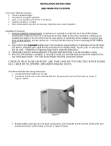
DVCS0070, DVU0050 and DVJR0060 Post Systems
(DVU0050PI and DVJR0060PI)
DVCS0070, DVU0050 and DVJR0060 Top Mount Post
Systems (DVU0050PA and DVJR0060PA)
Tools and/or Materials Required (not provided):
• Shovel or posthole digger
• Concrete mix and gravel (if backlling with concrete)
• Level, screwdriver, ½ inch open/box end wrench or socket set
• 4 J-shaped anchor bolts, lock washer and nuts
Note: Fastening hardware is included. Other tools/materials/hardware may also be necessary
depending upon actual installation.
Installation Procedure:
1. General Installation Requirements: Customers are required to contact the local Post Oce
before installing the mailbox to insure its correct placement and height at the street. Generally,
mailboxes are installed at a height of 41–45 inches from the road surface to inside oor of the
mailbox or point of mail entry (locked designs) and are set back 6 – 8 inches from front face of
curb or road edge to the mailbox door.
2. Dig a hole for the in-ground mailbox post. Hole should be approximately 6″ in diameter and
16–17″ deep. Use level to straighten pole, back ll hole and tamp dirt as needed. Note: If
backlling post hole with concrete, follow the concrete manufacturer’s instructions for setting
posts in concrete footings.
2. Align top plate and mailbox to post. The at side of the mounting plate should rest against
the bottom of the mailbox. There are four 5/16″-18 C hex head bolts and washers provided
with the post to attach the mailbox and mounting plate to the post. Open key-locked access
door and install four 5/16″-18 C hex head bolts with washers through the oor of the mailbox,
through the interior holes in the mounting plate and into the xed machine nuts in the post, and
tighten as needed.
CONCRETE MUST BE BELOW FROST LINE. TAKE CARE NOT TO PUNCTURE WATER, SEWER,
GAS, CABLE OR TELEPHONE LINES WHEN DIGGING HOLES.
Tools and/or Materials Required (not provided):
• Shovel or posthole digger
• Concrete mix and gravel
• Level, screwdriver, ½ inch open/box end wrench or socket set
• 4 J-shaped anchor bolts and nuts (for new concrete) OR 4 wedge-type concrete anchors, nuts
and hammer drill (for exsisting concrete)
Note: Fastening hardware is included. Other tools/materials/hardware may also be necessary
depending upon actual installation.
Installation Procedure:
1. General Installation Requirements: Customers are required to contact the local Post Oce
before installing the mailbox to insure its correct placement and height at the street. Generally,
mailboxes are installed at a height of 41–45 inches from the road surface to inside oor of the
mailbox or point of mail entry (locked designs) and are set back 6 – 8 inches from front face of
curb or road edge to the mailbox door.
2. Above ground mailbox post and concrete footing. You will need approximately 4 cu ft. The top
surface of the footing should be about 12″ by 12″ and extend 20″ into the ground. The bottom
of the hole for the concrete footing should be lled with about 4″ of gravel for drainage under the
post.
3. Attach the bottom mounting plate to the bottom of the post using the 4 included Phillips head
countersink machine screws and tighten as needed. The at side of the mounting plate should
rest on the concrete, and the countersunk screws and plate should create a ush surface.
4a. If new concrete is being poured, attach 4 J-shaped anchor bolts to the base of the post with 4
nuts under and 4 nuts over the bottom mounting plate. Pour the concrete into the hole with a
stick while lling to reduce any air pockets. Press the anchor bolts on the bottom of the post
into the concrete until the bottom plate is resting on the top surface of the wet concrete. Use
a level on the sides of the post to ensure that the post is aligned vertically. Periodically check
the vertical alignment of the post as the concrete is curing.
4b. If attaching to existing concrete, we recommend using
wedge-style concrete anchors. Be sure to follow the anchor
manufacturer’s instructions for installation, as the process may
vary slightly by manufacturer. See gure for spacing of concrete
mounting holes on the bottom mounting plate.
CONCRETE MUST BE BELOW FROST LINE. TAKE CARE NOT TO
PUNCTURE WATER, SEWER, GAS, CABLE OR TELEPHONE LINES WHEN DIGGING HOLES.
dVault
®
Companies, Inc. • Secure mail collection solutions. • www.dvault.com • (719) 955-2698 • Fax: (719) 531-5617dVault
®
Companies, Inc. • Secure mail collection solutions. • www.dvault.com • (719) 955-2698 • Fax: (719) 531-5617
Top Mount, In Ground Installation Top Mount, Above Ground Installation

Side Mount, In Ground Installation
Post Installation Instructions
Posts for dVault Locking Mailboxes
DVJR0060 Series Post Systems (DVJR0060SMPI)
Side Mount Post Systems
(DVJR0060SMPI)
Above Ground Post Systems
(DVU0050PA and DVJR0060PA)
Tools and/or Materials Required (not
provided):
• Shovel or posthole digger
• Concrete mix and gravel (optional)
• Level
• ½ inch open/box end wrench or socket set.
Note: Fastening hardware is included. Other
tools/materials/hardware may also be necessary
depending upon actual installation.
Installation Procedure:
1. General Installation Requirements:
Customers are required to contact the local
Post O ce before installing the mailbox to
insure its correct placement and height at
the street. Generally, mailboxes are installed
at a height of 41–45" from the road surface
to inside oor of the mailbox or point of mail
entry (locked designs) and are set back 6–8"
from front face of curb or road edge to the
mailbox door.
2. Dig a hole for the in-ground mailbox post.
Hole should be approximately 6" in diameter
and 24–28" deep. Use level to straighten
pole, back ll hole and tamp dirt as needed
(Note: “Quick Crete” or concrete may also be
used.
3. Periodically check the vertical alignment of
the post with level when back lling or as the
concrete is curing.
4. When back ll tamping is complete, or
concrete is cured, you are now ready to
mount the mailbox to the side mount post
system.
CONCRETE MUST BE BELOW FROST LINE.
TAKE CARE NOT TO PUNCTURE WATER,
SEWER, GAS, CABLE OR TELEPHONE LINES
WHEN DIGGING HOLES.
Side Mount Mailbox Mounting Instructions:
1. Locate and place mailbox on its side.
2. Locate the knock
outs on the side that
will face the post and
knock out the holes as
shown in Figure 1.
3. Rotate mailbox and
place it on its side.
Locate the knock outs
that will face the post
bracket and knock out
the holes as shown in
Figure 2.
4. Install under-unit
support bracket to post using two of the
provided 5/16" – 18 hex bolts and lock
washers. Tighten as needed
5. Locate mailbox keys and open access door
in the fully open position.
6. Place and align the mailbox on the post
bracket over the bottom set of holes as
shown below, and install two of the provided
5/16" – 18 hex bolts and lock washers
through the bottom
knockouts of the unit into
the threaded holes of
the previously installed
under-unit support
bracket. Tighten as
needed.
7. Install two nal
5/16" – 18 hex bolts and
lock washers through the
side of the mailbox using
the side knockouts that were previously
removed. Tighten as needed.
dVault
®
Companies, Inc. • Secure mail collection solutions. • www.dvault.com • (719) 955-2698 • Fax: (719) 531-5617
dVault
®
Companies, Inc.
Secure mail collection solutions.
www.dvault.com
(719) 955-2698
Fax: (719) 531-5617
dVault is proud to manufacture 100% of their locking mailboxes, parcel vaults, and posts in the USA.
Based in Colorado, dVault has over 30 years of manufacturing experience, and is dedicated to the
highest level of quality.
Mail Protector Vault
DVCS0070
Weekend Away Vault
DVJR0060
Parcel Protector Vault
DVU0050
In Ground Post Systems
(DVU0050PI and DVJR0060PI)
-
 1
1
-
 2
2
Ask a question and I''ll find the answer in the document
Finding information in a document is now easier with AI
Related papers
Other documents
-
Anvil 618010 Installation guide
-
 Architectural Mailboxes 7516P Installation guide
-
SereneLife SLMAB06 Owner's manual
-
Barska CB13256 User manual
-
Postal Pro PP3400BLM Operating instructions
-
 Mailbox Post Solutions Return-to-Center SwingAway Mailbox Support Installation guide
-
Gaines Manufacturing KSP-BRO User manual
-
 Postal Pro PP330CBLM Operating instructions
-
Eye Level 50-RFLEX6V1 Installation guide
-
 Gaines Manufacturing KS-1A User guide


