Honeywell QUANTUME IS3480 User manual
- Category
- Bar code readers
- Type
- User manual
This manual is also suitable for

IS3480 QuantumE
®
Scan Engine
User’s Guide

Disclaimer
Honeywell International Inc. (“HII”) reserves the right to make changes in
specifications and other information contained in this document without prior
notice, and the reader should in all cases consult HII to determine whether any
such changes have been made. The information in this publication does not
represent a commitment on the part of HII.
HII shall not be liable for technical or editorial errors or omissions contained
herein: nor for incidental or consequential damages resulting from the furnishing,
performance, or use of this manual.
This document contains propriety information that is protected by copyright.
All rights reserved. No part of this document may be photocopied, reproduced,
or translated into another language without the prior written consent of HII.
© 2004 - 2010 Honeywell International Inc. All rights reserved.
Web Address: www.honeywellaidc.com
Trademarks
Metrologic, QuantumE, CodeGate, MetroSelect and MetroSet2 are trademarks or
registered trademarks of Metrologic Instruments, Inc. or Honeywell International
Inc.
Microsoft, Windows 95, and Windows are registered trademarks of Microsoft
Corporation.
IBM is a trademark of International Business Machines Corporation.
Checkpoint is a registered trademark of Checkpoint Systems, Inc.
Other product names mentioned in this manual may be trademarks or
registered trademarks of their respective companies and are the property of their
respective owners.

ii
TABLE OF CONTENTS
Introduction
Product Overview ............................................................................................. 1
Scanner and Accessories ................................................................................. 2
Maintenance ..................................................................................................... 3
Scanner Components ....................................................................................... 4
Cable Removal ................................................................................................. 4
Caution and Serial Number Labels ................................................................... 5
Mounting Specifications ................................................................................... 5
Installation
RS232, RS232 TTL, Light Pen or Laser Emulation .......................................... 6
RS485 .............................................................................................................. 7
Keyboard Wedge .............................................................................................. 8
Stand-Alone Keyboard ..................................................................................... 9
Low Speed USB (Integrated) .......................................................................... 10
Notes for Laser Emulation .............................................................................. 11
Scanner Operation
Configurable Primary and Secondary Scan Pattern Modes ........................... 12
Configurable Button Functions ....................................................................... 12
Sweet Spot Mode ........................................................................................... 17
Indicators
Audible ....................................................................................................... 18
Visual ......................................................................................................... 19
Failure ........................................................................................................ 20
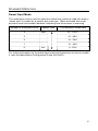
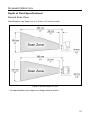
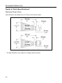
Depth of Field Specifications
Normal Scan Zone ..................................................................................... 21
Reduced Scan Zone ................................................................................... 22
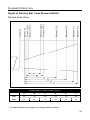
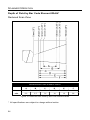
Depth of Field by Bar Code Element Width
Normal Scan Zone ..................................................................................... 23
Reduced Scan Zone ................................................................................... 24

iii
TABLE OF CONTENTS
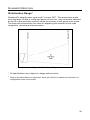
IR Activation Range ........................................................................................ 25
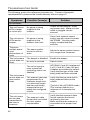
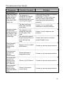
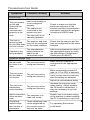
Troubleshooting Guide ....................................................................................... 26
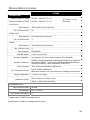
Design Specifications ......................................................................................... 29
Applications and Protocols ................................................................................. 31
Configuration Modes .......................................................................................... 32
Upgrading the Firmware ..................................................................................... 33
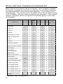
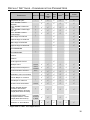
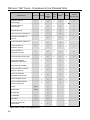
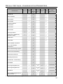
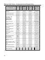
Default Settings - Communication Parameters ................................................... 34
Scanner and Cable Terminations ....................................................................... 39
Regulatory Compliance
Safety ............................................................................................................. 44
EMC ............................................................................................................... 45
Limited Warranty ................................................................................................ 47
Patents ............................................................................................................... 49
Index .................................................................................................................. 50
Customer Support .............................................................................................. 52
Technical Assistance ...................................................................................... 52
Product Service and Repair ............................................................................ 53

1
INTRODUCTION
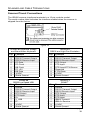
QuantumE
®
is a miniature, omni-directional scanning engine with optional single-
line scanning capability. The self-contained device is fully enclosed eliminating
the need for an external window or custom enclosure. It is designed for use in
OEM equipment such as price lookup systems and kiosks. QuantumE s slim
design makes it ideal for integration and use with flat-screens.
Key Product Features
• Fully Automatic Scanning Operation
• Custom Configurable Scan Pattern
• User-Replaceable Single Cable Interface to Host (PowerLink Compatible)
• Decoding of All Standard 1D and GS1 DataBar™ (RSS) Bar Codes
• Data Editing
• Seven Beeper Tones
• Configurable Depth of Field
• Flash - Upgradeable Firmware
• CodeGate
®
• Sunrise 2005 Compliant
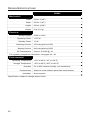
SCANNER INTERFACE
IS3480-11 RS485
and Full RS232
IS3480-38
RS232 Low Speed USB,
Keyboard Emulation or Serial Emulation
IS3480-41 RS232/Light Pen Emulation
IS3480-47
Keyboard Wedge, Stand-Alone Keyboard and
RS232 Transmit/Receive
IS3480-104 RS232 TTL, Laser Emulation
Applicable for IBM
®
Host applications.

2
INTRODUCTION
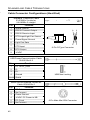
Scanner and Accessories
BASIC KIT COMPONENTS
Part No. Description
IS3480 QuantumE Scanner
00-02026 IS3480 Installation and User’s Guide *
00-02407 MetroSelect
®
Configuration Guide *
* Guides also available for download at www.honeywellaidc.com.
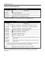
OPTIONAL ACCESSORIES
Part No. Description
AC to DC Power Transformer - Regulated 5.2VDC @ 1A output.
46-00525 90VAC to 255VAC United States, Canada and Japan
46-00526 90VAC to 255VAC Continental European
46-00527 90VAC to 255VAC United Kingdom
46-00528 90VAC to 255VAC Australia
46-00529 90VAC to 255VAC China
46-00530 90VAC to 255VAC India
59-59000-3
(default)
PowerLink cable with built in power jack straight cord, short
strain relief
53-53000-3
(optional)
PowerLink cable with built in power jack coiled cord, long
strain relief
** Contact a customer service representative for additional information on
the MVC cable series and the host connections available.
MVC** Voltage Converter Cable ±12VDC to +5.2VDC
Other items may be ordered for the specific protocol being used. To order additional
items, contact the dealer, distributor or customer service
. See page 52 for contact
information
.

3
INTRODUCTION
Scanner and Accessories
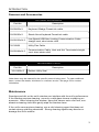
OPTIONAL ACCESSORIES
Part No. Description
59-59002x-3 Keyboard Wedge PowerLink cable
59-59020x-3 Stand Alone Keyboard PowerLink cable
59-59235x-N-3
Low Speed USB Non-Locking Communication Cable
straight cord, short strain relief
35-35959 Utility Flex Cable
59-59249x-N-3
Communication Cable, Host end Not Terminated straight
cord, short strain relief
REPLACEMENT PARTS
Part No. Description
36-01822x-3 Rubber Utility Seal
Other items may be ordered for the specific protocol being used. To order additional
items, contact the dealer, distributor or customer service
. See page 52 for contact
information.
Maintenance
Smudges and dirt on the unit's window can interfere with the unit's performance.
If the window requires cleaning, use only a mild glass cleaner containing no
ammonia. When cleaning the window, spray the cleaner onto a lint free, non-
abrasive cleaning cloth then gently wipe the window clean.
If the unit's case requires cleaning, use a mild cleaning agent that does not
contain strong oxidizing chemicals. Strong cleaning agents may discolor or
damage the unit's exterior.

4
INTRODUCTION
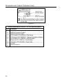
Scanner Components
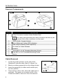
Figure 1a. Scanner Components
ITEM NO. DESCRIPTION
1 Utility Connector Located Under Rubber Seal
The rubber seal protecting the utility connector should only be
removed if the utility connector is to be used.
2 10-Pin RJ45, Female Socket
3 Blue, White and Yellow LED Indicators
4 Red Output Window (Laser Aperture)
5 Pin Hole for Cable Release
6 Speaker
7 Three M2.5 x 0.45 Threaded Mounting Points
8 Two M2.5 x 0.45 Threaded Mounting Points
9 Button
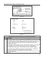
Cable Removal
1. Locate the small ‘pinhole’ on the side of the
QuantumE near the cable (item 5 in figure 1a).
2. Bend an ordinary paperclip into the shape shown.
3. Insert the paperclip (or other small metallic pin)
into the ‘pinhole’.
4. There will be a faint ‘click’ when the cable lock is
released. Pull gently on the strain-relief of the
PowerLink cable to remove it from the scanner.
Figure 1b.
5
INTRODUCTION
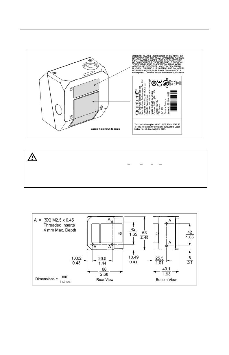
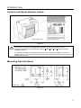
Caution and Serial Number Labels
Figure 2.
Caution
To maintain compliance with applicable standards, all circuits connected to the
scanner must meet the requirements for SELV (Safety Extra Low Voltage) according
to EN/IEC 60950-1.
To maintain compliance with standard CSA C22.2 No. 60950-1/UL 60950-1 and norm
EN/IEC 60950-1, the power source should meet applicable performance requirements for a
limited power source.
Mounting Specifications
Figure 3.

6
INSTALLATION
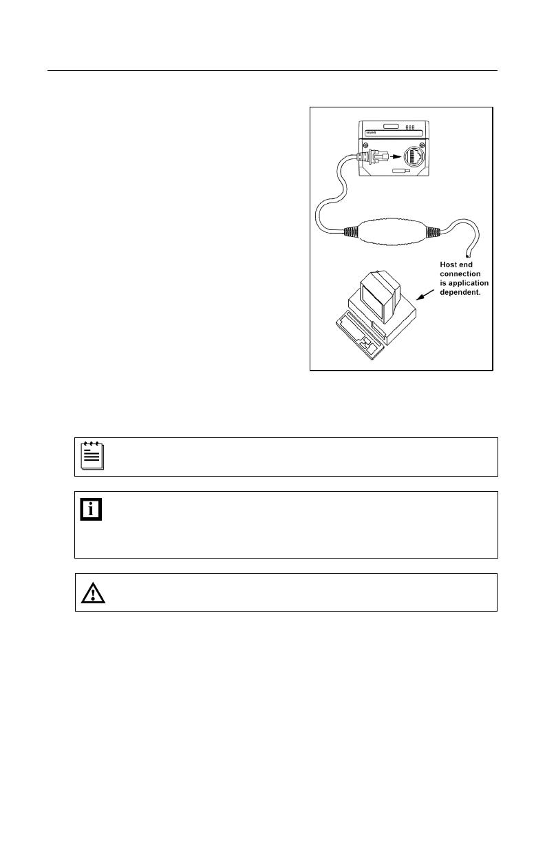
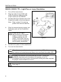
RS232, RS232 TTL, Light Pen or Laser Emulation
1. Turn off the host device.
2. Plug the male 10-pin RJ45 end
of the PowerLink cable into the
10-pin socket on the IS3480.
3. Connect the 9-pin female end of the
PowerLink cable to the host device.
Note: Skip to step 6 if receiving
power from the host device.
4. Plug the external power supply into
the power jack on the PowerLink
cable.
Check the AC input
requirements of the power
supply to make sure the
voltage matches the AC
outlet. The outlet must be
located near the equipment
and be easily accessible.
5. Connect AC power to the transformer.
6. Turn on the host device.
When the scanner first receives power, the blue LED will turn on;
the scanner will simultaneously beep once and flash the white LED.
Plugging the scanner into the serial port of the PC does not
guarantee that scanned information will appear at the PC.
A software driver and correct configuration setting are also required
for proper communication to occur.
See page 5.
Figure 4.
7
INSTALLATION
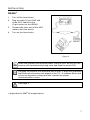
RS485
1. Turn off the host device.
2. Plug the male 10-pin RJ45 end
of the MVC cable into the
10-pin socket on the IS3480.
3. Connect the other end of the MVC
cable to the host device.
4. Turn on the host device.
When the scanner first receives power, the blue LED will turn on; the
scanner will simultaneously beep once and flash the white LED.
Plugging the scanner into the serial port of the PC does not guarantee
that scanned information will appear at the PC. A software driver and
correct configuration setting are also required for proper
communication to occur.
See page 5.
Applicable for IBM
®
Host applications.
Figure 5.

8
INSTALLATION
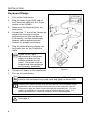
Keyboard Wedge
1. Turn off the host device.
2. Plug the male 10-pin RJ45 end of
the PowerLink cable into the 10-pin
socket on the IS3480.
3. Disconnect the keyboard from the
host device.
4. Connect the “Y” end of the PowerLink
cable to the keyboard and the
keyboard port on the host device.
If necessary, use the male/female
adapter cable supplied with the
scanner for proper connections.
5. Plug the external power supply into
the power jack on the PowerLink
cable.
Check the AC input
requirements of the power
supply to make sure the
voltage matches the AC
outlet. The outlet must be
located near the equipment
and be easily accessible.
6. Connect AC power to the transformer.
7. Turn on the host device.
When the scanner first receives power, the blue LED will turn on; the
scanner will simultaneously beep once and flash the white LED.
Powering the IS3480 directly from the host device can sometimes cause
interference with the operation of the scanner or the computer. Not all
computers supply the same current through the keyboard port. For this
reason, Honeywell recommends using an external power supply. For
additional information, contact a customer service representative.
See page 5.
Figure 6.

9
INSTALLATION
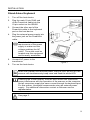
Stand-Alone Keyboard
1. Turn off the host device.
2. Plug the male 10-pin RJ45 end
of the PowerLink cable into the
10-pin socket on the IS3480.
3. Connect the other end of the
PowerLink cable to the keyboard
port on the host device.
4. Plug the external power supply into
the power jack on the PowerLink
cable.
Check the AC input
requirements of the power
supply to make sure the
voltage matches the AC
outlet. The outlet must be
located near the equipment
and be easily accessible.
5. Connect AC power to the
transformer.
6. Turn on the host device.
When the scanner first receives power, the blue LED will turn on; the
scanner will simultaneously beep once and flash the white LED.
Powering the IS3480 directly from the host device can sometimes
cause interference with the operation of the scanner or the computer.
Not all computers supply the same current through the keyboard port.
For this reason, Honeywell recommends using an external power
supply. For additional information contact a customer service
representative.
See page 5.
Figure 7.

10
INSTALLATION
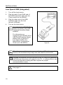
Low Speed USB (Integrated)
1. Turn off the host device.
2. Plug the male 10-pin RJ45 end of
the USB PowerLink cable into the
10-pin socket on the IS3480.
3. Plug the other end of the USB
interface cable into the host
device’s USB port.
4. Turn on the host device.
As a default, the IS3480-38
leaves the factory with USB
Keyboard Emulation Mode
enabled.
For information on
configuring the IS3480-38 for
USB Serial Emulation Mode,
please refer to Section P:
Low Speed USB in the
MetroSelect Configuration
Guide (MLPN 00-02407).
When the scanner first receives power, the blue LED will turn on; the
scanner will simultaneously beep once and flash the white LED.
Plugging the scanner into the USB port of the PC does not guarantee
that scanned information will appear at the PC. A software driver and
correct configuration setting are also required for proper
communication to occur.
See page 5.
Figure 8.

11
INSTALLATION
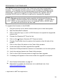
Notes for Laser Emulation
IS3480-104 Only
The IS3480-104 leaves the factory with the Laser Emulation Mode enabled.
If the Recall Defaults bar code is scanned while reconfiguring the scanner, the
laser emulation mode will no longer be enabled.
Scan the following bar code to re-enable the laser emulation interface.
This feature is only supported for IS3480-104 models.
Enable Laser Emulation Mode
³999979
12
SCANNER OPERATION
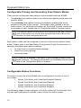
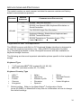
Configurable Primary and Secondary Scan Pattern Modes
There are two configurable scan pattern modes available with the IS3480.
• The primary scan pattern mode is the default scan pattern active when the
scanner starts.
• The secondary scan pattern mode is activated by pressing the button
located on the side of the scanner. This mode is also referred to as the
button mode. For additional information on QuantumE’s button modes and
an example of each, please refer to Configurable Button Functions below.
The scanner returns to the primary scan pattern mode after a double
click of the button or if the unit has not scanned a bar code for the
duration of a pre-configured time limit.
Each pattern mode can be configured to use one of three scan patterns listed
below. Please refer to the MetroSelect Configuration Guide for information on
changing the default scan pattern settings.
• all scan lines on (omnidirectional reading)
• single-line (menu reading)
• horizontal raster
If CodeGate is enabled, it will apply to the secondary pattern mode
when scanning. For detailed information on CodeGate and the button
refer to the Configurable Button Functions.
Configurable Button Functions
The button on the side of the IS3480 can be configured to function in one of
four modes.
• Button Click Mode, with CodeGate Enabled (Default)
• Button Click Mode, with CodeGate Disabled
• Button Hold Mode, with CodeGate Enabled
• Button Hold Mode, with CodeGate Disabled
The following pages include examples of how the button will function when the
unit has been configured to operate in each of the four button modes.
13
SCANNER OPERATION
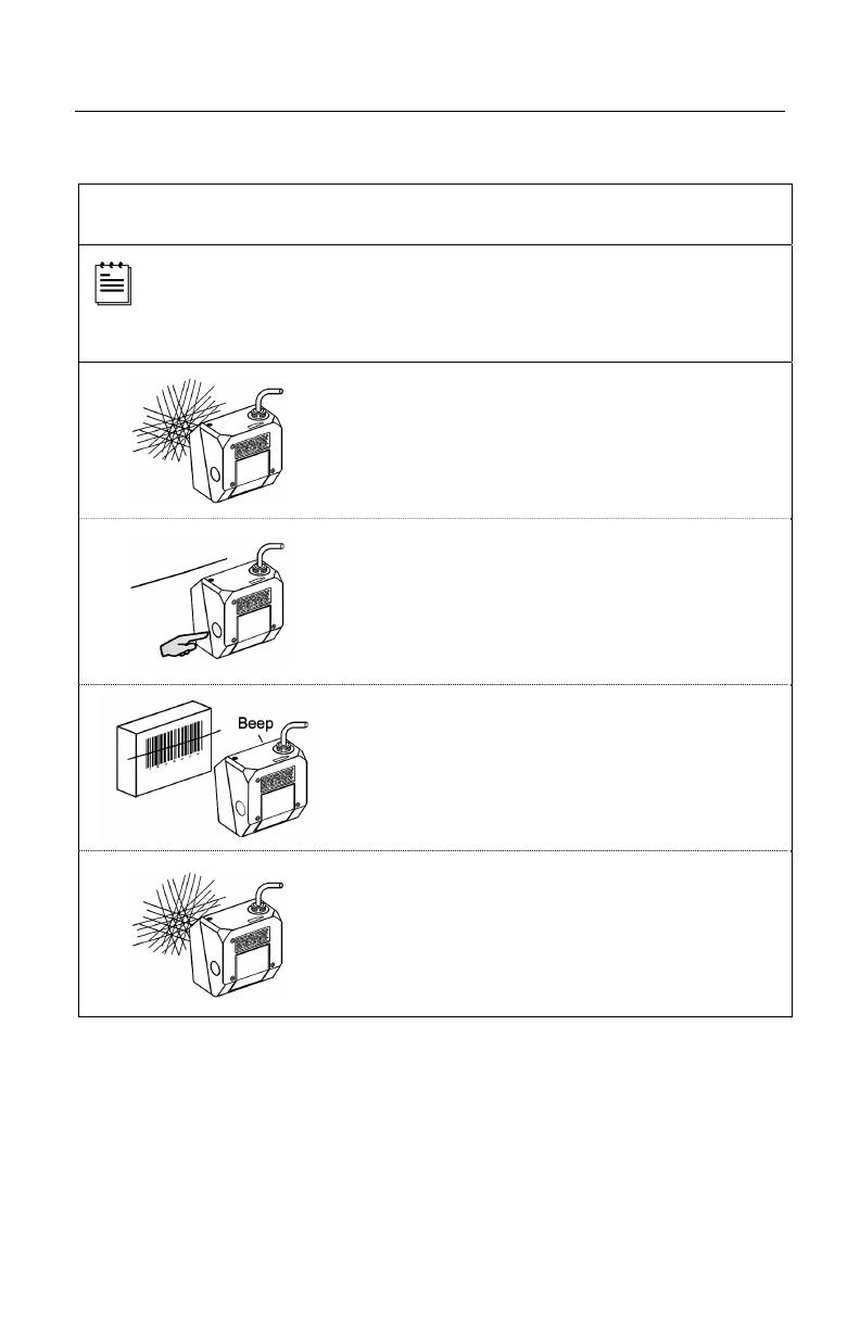
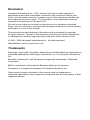
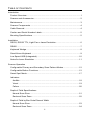
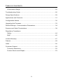
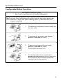
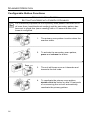
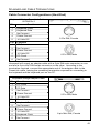
Configurable Button Functions
SECONDARY SCAN PATTERN
B
UTTON CLICK MODE WITH CODEGATE ENABLED
For illustration purposes the unit’s primary scan pattern has been set to
all scan lines (omnidirectional reading) and the secondary pattern has
been set to single-line (menu reading) with a 10 second button click
timeout configured.
1. The primary scan pattern is active when the
scanner starts.
2. To activate the secondary scan pattern,
press and release the button.
3. To decode and transmit the bar code,
press and release the button.
The scanner will beep once.
4. To reactivate the primary scan pattern,
double click the button or after 10-seconds
of no-scanning the unit will automatically
reactivate the primary pattern.
14
SCANNER OPERATION
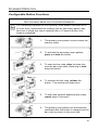
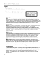
Configurable Button Functions
SECONDARY SCAN PATTERN
B
UTTON CLICK MODE WITH CODEGATE DISABLED
For illustration purposes the unit’s primary scan pattern has been set to
all scan lines (omnidirectional reading) and the secondary pattern has
been set to single-line (menu reading) with a 10 second button click
timeout configured.
1. The primary scan pattern is active when the
scanner starts.
2. To activate the secondary scan pattern,
press and release the button.
3. The unit will beep once as it decodes and
transmits the bar code.
4. To reactivate the primary scan pattern,
double click the button or after 10-seconds
of no-scanning the unit will automatically
reactivate the primary pattern.

15
SCANNER OPERATION
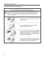
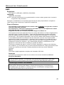
Configurable Button Functions
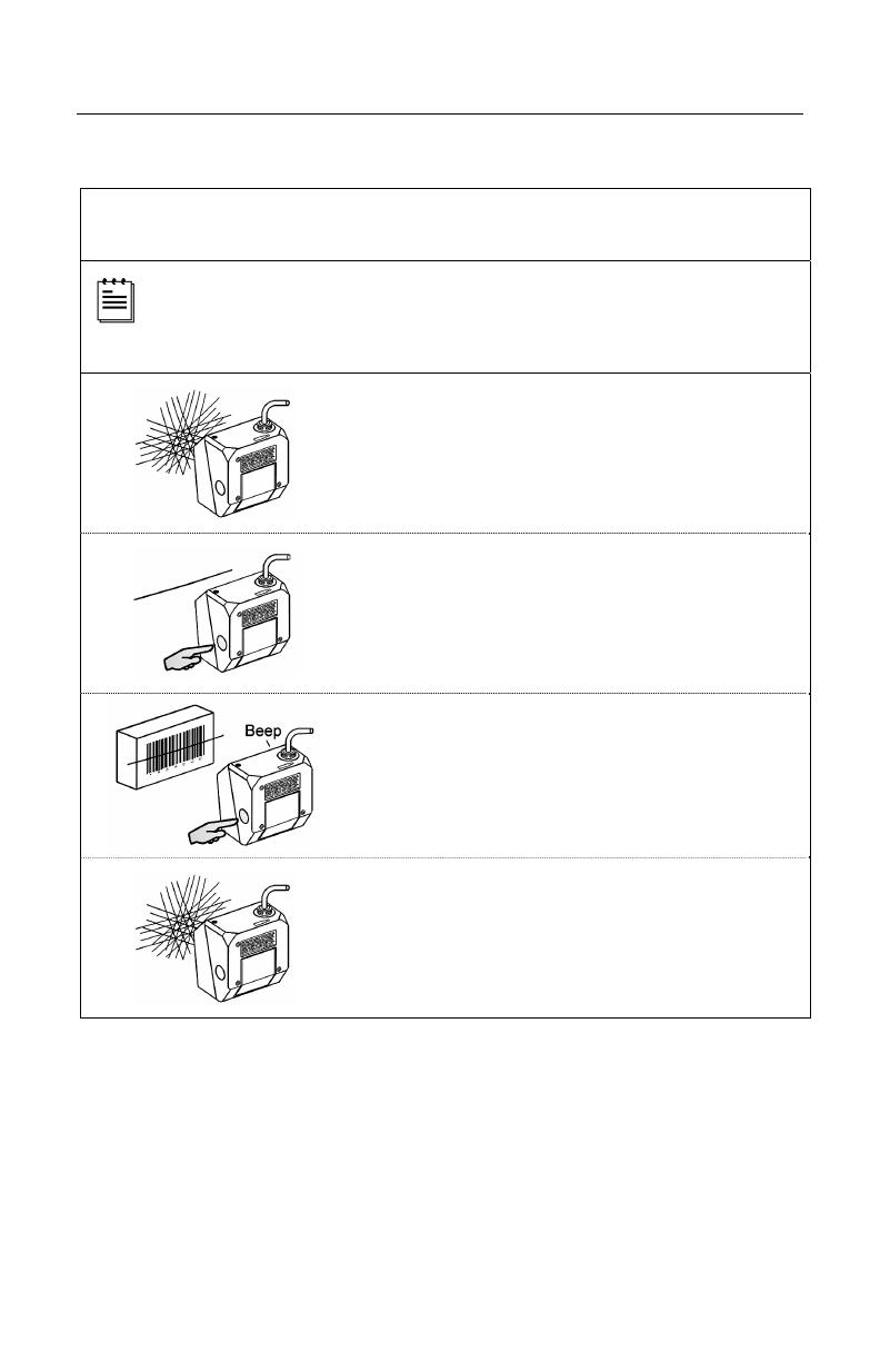
SECONDARY SCAN PATTERN
B
UTTON HOLD MODE WITH CODEGATE ENABLED
For illustration purposes the unit’s primary scan pattern has been set to
all scan lines (omnidirectional reading) and the secondary pattern has
been set to single-line (menu reading) with a 10 second button click
timeout configured.
1. The primary scan pattern is active when the
scanner starts.
2. To activate the secondary scan pattern,
press and hold the button.
3. To scan the bar code, align the laser line
over the bar code while continuing to hold
down the button.
4. To transmit the bar code, release the
button. The scanner will beep once.
5. To scan and transmit additional bar codes,
repeat steps 2 through 4.
6. The primary scan pattern will automatically
reactivate after the button is released and no
bar code is present in the scan field.

16
SCANNER OPERATION
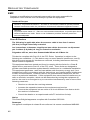
Configurable Button Functions
SECONDARY SCAN PATTERN
B
UTTON HOLD MODE WITH CODEGATE DISABLED
For illustration purposes the unit’s primary scan pattern has been set to
all scan lines (omnidirectional reading) and the secondary pattern has
been set to single-line (menu reading) with a 10 second button click
timeout configured.
1. The primary scan pattern is active when the
scanner starts.
2. To activate the secondary scan pattern,
press and hold the button.
3. To scan and transmit the bar code, align the
laser line over the bar code while continuing
to hold down the button. The scanner will
beep once to indicate the bar code has been
scanned and transmitted.
4. The primary scan pattern will automatically
reactivate after the button is released and no
bar code is present in the scan field.
Page is loading ...
Page is loading ...
Page is loading ...
Page is loading ...
Page is loading ...
Page is loading ...
Page is loading ...
Page is loading ...
Page is loading ...
Page is loading ...
Page is loading ...
Page is loading ...
Page is loading ...
Page is loading ...
Page is loading ...
Page is loading ...
Page is loading ...
Page is loading ...
Page is loading ...
Page is loading ...
Page is loading ...
Page is loading ...
Page is loading ...
Page is loading ...
Page is loading ...
Page is loading ...
Page is loading ...
Page is loading ...
Page is loading ...
Page is loading ...
Page is loading ...
Page is loading ...
Page is loading ...
Page is loading ...
Page is loading ...
Page is loading ...
Page is loading ...
Page is loading ...
Page is loading ...
Page is loading ...
-
 1
1
-
 2
2
-
 3
3
-
 4
4
-
 5
5
-
 6
6
-
 7
7
-
 8
8
-
 9
9
-
 10
10
-
 11
11
-
 12
12
-
 13
13
-
 14
14
-
 15
15
-
 16
16
-
 17
17
-
 18
18
-
 19
19
-
 20
20
-
 21
21
-
 22
22
-
 23
23
-
 24
24
-
 25
25
-
 26
26
-
 27
27
-
 28
28
-
 29
29
-
 30
30
-
 31
31
-
 32
32
-
 33
33
-
 34
34
-
 35
35
-
 36
36
-
 37
37
-
 38
38
-
 39
39
-
 40
40
-
 41
41
-
 42
42
-
 43
43
-
 44
44
-
 45
45
-
 46
46
-
 47
47
-
 48
48
-
 49
49
-
 50
50
-
 51
51
-
 52
52
-
 53
53
-
 54
54
-
 55
55
-
 56
56
-
 57
57
-
 58
58
-
 59
59
-
 60
60


Honeywell QUANTUME IS3480 User manual
- Category
- Bar code readers
- Type
- User manual
- This manual is also suitable for
Ask a question and I''ll find the answer in the document
Finding information in a document is now easier with AI
Related papers
-
Honeywell MK3480-30B104 - IS3480 QuantumE - Wired Desktop Barcode Scanner User manual
-
Metrologic IS3480 QuantumE User manual
-
-
Honeywell 1900 User manual
-
-
-
-
Metrologic Orbit MS7120-38 User manual
-
-
Other documents
-
Metrologic IS3480 QuantumE Installation and User Manual
-
-
-
Metrologic Instruments IS3480 User manual
-
-
-
-
Opticon LPN 1736 User manual
-
-
BTC 9116 User manual