Garmin GPSMAP 7407 Installation guide
- Category
- Navigators
- Type
- Installation guide
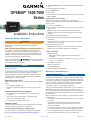
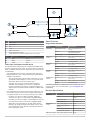
Garmin GPSMAP 7407: Navigate and explore the waters with advanced charting, networking, and connectivity features. Experience superior situational awareness with high-resolution mapping, crisp sonar imaging, and comprehensive sailing instruments. Stay connected on the water with built-in Wi-Fi and NMEA 2000 compatibility, allowing you to share data and control peripherals effortlessly.
Garmin GPSMAP 7407: Navigate and explore the waters with advanced charting, networking, and connectivity features. Experience superior situational awareness with high-resolution mapping, crisp sonar imaging, and comprehensive sailing instruments. Stay connected on the water with built-in Wi-Fi and NMEA 2000 compatibility, allowing you to share data and control peripherals effortlessly.


-
 1
1
-
 2
2
-
 3
3
-
 4
4
-
 5
5
-
 6
6
-
 7
7
-
 8
8


Garmin GPSMAP 7407 Installation guide
- Category
- Navigators
- Type
- Installation guide
Garmin GPSMAP 7407: Navigate and explore the waters with advanced charting, networking, and connectivity features. Experience superior situational awareness with high-resolution mapping, crisp sonar imaging, and comprehensive sailing instruments. Stay connected on the water with built-in Wi-Fi and NMEA 2000 compatibility, allowing you to share data and control peripherals effortlessly.
Ask a question and I''ll find the answer in the document
Finding information in a document is now easier with AI
Related papers
-
Garmin GPSMAP 8008 Owner's manual
-
Garmin GPSMAP® 7616xsv Owner's manual
-
Garmin GPSMAP 7416 Owner's manual
-
Garmin GPSMAP 10X2/12X2 Series Owner's manual
-
Garmin GPSMAP User manual
-
Garmin 010-01740-03 Installation guide
-
Garmin GPSMAP 722xs Plus bundel Owner's manual
-
Garmin GPSMAP® 8410xsv Installation guide
-
-
Garmin GPSMAP 10×2 Series 10 Inch All In One Chartplotter User manual
Other documents
-
Yamaha CL7 Installation guide
-
Extron SMB 303 Template
-
Wet Sounds WS-NMEA-TR Owner's manual
-
Edsal Bookcase Wall Fastening Directions Assembly Manual
-
GME G-combo G142CFD User manual
-
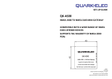 Quark-Elec QK-AS00 Installation guide
-
Quark-Elec QUARK-ELEC QK-AS01 NMEA 0183 to NMEA 2000 Mini Gateway User manual
-
Quark-Elec QUARK-ELEC QK-AS00 NMEA 2000 to NMEA 0183 Mini Gateway Operating instructions
-
-
 Standard STDMLS310B User manual

