Page is loading ...

CL7 DISPLAY
Installation Instructions
Important Safety Information
WARNING
See the Important Safety and Product Information guide in the
product box for product warnings and other important
information.
When connecting the power cable, do not remove the in-line
fuse holder. To prevent the possibility of injury or product
damage caused by fire or overheating, the appropriate fuse
must be in place as indicated in the product specifications. In
addition, connecting the power cable without the appropriate
fuse in place voids the product warranty.
Always wear safety goggles, ear protection, and a dust mask
when drilling, cutting, or sanding.
NOTICE
When drilling or cutting, always check what is on the opposite
side of the surface.
To obtain the best performance and to avoid damage to your
boat, install the device according to these instructions.
Read all installation instructions before proceeding with the
installation. If you experience difficulty during the installation,
contact your Yamaha® dealer.
Tools Needed
• Appropriate pigtail bus wire for engine network connection
• Drill and drill bits
◦ 3.2 mm (1/8 in.) drill bit, if using wood screws
◦ 3.6 mm (9/64 in.) drill bit, if using the nut plates (optional
accessory)
◦ 7.2 mm (9/32 in.) drill bit, if using the nut plates (optional
accessory)
• Mounting hardware
◦ 4 Wood screws (included)
◦ 4 M4 machine screws if using the nut plates (included with
nut plate accessory)
◦ 4 M3 machine screws if using the nut plates (included with
nut plate accessory)
• #2 Phillips screwdriver
• Jigsaw or rotary tool
• File and sandpaper
• Marine sealant (recommended)
Mounting Considerations
NOTICE
This device should be mounted in a location that is not exposed
to extreme temperatures or conditions. The temperature range
for this device is listed in the product specifications. Extended
exposure to temperatures exceeding the specified temperature
range, in storage or operating conditions, may cause device
failure. Extreme-temperature-induced damage and related
consequences are not covered by the warranty.
When selecting a mounting location, you should observe these
considerations.
• The location should provide optimal viewing as you operate
your boat.
• The location should allow for easy access to all device
interfaces, such as the keypad, touchscreen, and card
reader, if applicable.
• The location must be strong enough to support the weight of
the device and protect it from excessive vibration or shock.
• To avoid interference with a magnetic compass, the device
should not be installed closer to a compass than the
compass-safe distance value listed in the product
specifications.
• The location must allow room for the routing and connection
of all cables.
• The location must not be a flat, horizontal surface. The
location should be in a vertical angle.
The location and viewing angle should be tested before you
install the device. High viewing angles from above and below
the display may result in a poor image.
Mounting the Device
NOTICE
Be careful when cutting the hole to flush mount the device.
There is only a small amount of clearance between the case and
the mounting holes, and cutting the hole too large could
compromise the stability of the device after it is mounted.
There are different options for hardware based on the mounting
surface material. You may need additional hardware depending
on the mounting option selected.
• You can drill pilot holes and use the included wood screws.
• You can drill holes and use nut plates and machine screws
(optional accessory). The nut plates can add stability to a
thinner surface.
1Trim the template and make sure it fits in the location where
you want to mount the device.
2Secure the template to the selected location.
3Using a 13 mm (1/2 in.) drill bit, drill one or more of the holes
inside the corners of the solid line on the template to prepare
the mounting surface for cutting.
4Using a jigsaw or a rotary tool, cut the mounting surface
along the inside line on the template.
5Place the device in the cutout to test the fit.
6If necessary, use a file and sandpaper to refine the size of
the cutout.
7After the device fits correctly in the cutout, ensure the
mounting holes on the device line up with the larger holes in
the corners of the template.
8If the mounting holes on the device do not line up, mark the
new hole locations.
9Based on your mounting surface, drill or punch and tap the
larger holes:
• Drill 3.2 mm (1/8 in.) pilot holes for wood screws, and skip
to step 17.
• Drill 7.2 mm (9/32 in.) holes for the nut plate and machine
screws, and continue to the next step.
10If using the nut plates (optional accessory), starting in one
corner of the template, place a nut plate À over the larger
hole Á drilled in step 9.
March 2018
190-02076-02_0B
6YD-2819K-E0

The smaller hole  on the nut plate should line up with the
smaller hole on the template.
11If the smaller 3.6 mm (9/64 in.) hole on the nut plate does not
line up with the smaller hole on the template, mark the new
location.
12Repeat steps 10 and 11 for each nut plate.
13Using a 3.6 mm (9/64 in.) drill bit, drill the smaller holes.
14Starting in one corner of the mounting location, place a nut
plate à on the back of the mounting surface, lining up the
large and small holes.
The raised portion of the nut plate should fit into the larger
hole.
15Secure the nut plate to the mounting surface by fastening an
M3 screw Ä through the smaller 3.6 mm (9/64 in.) hole.
16Repeat steps 14 and 15 for each of the nut plates along the
top and bottom of the device.
17Remove the template from the mounting surface.
18If you will not have access to the back of the device after you
mount it, connect all necessary cables to the device before
placing it into the cutout.
19To prevent corrosion of the metal contacts, cover unused
connectors with the attached weather caps.
20Apply marine sealant between the mounting surface and the
device to properly seal and prevent leakage behind the
dashboard.
21If you will have access to the back of the device, apply
marine sealant around the cutout.
22Place the device into the cutout.
23Secure the device to the mounting surface using M4 screws
Å or wood screws, depending on the mounting method.
24Wipe away all excess marine sealant.
25Install the decorative bezel by snapping it in place around the
edges of the device.
Connection Considerations
When connecting this device to power and to other Garmin®
devices, you should observe these considerations.
• The power and ground connections to the battery must be
checked to make sure they are secured and cannot become
loose.
• The cables may be packaged without the locking rings
installed. The cables should be routed before the locking
rings are installed.
• After installing a locking ring on a cable, you should make
sure the ring is securely connected and the o-ring is in place
so the power or data connection remains secure.
Connecting to Power
WARNING
When connecting the power cable, do not remove the in-line
fuse holder. To prevent the possibility of injury or product
damage caused by fire or overheating, the appropriate fuse
must be in place as indicated in the product specifications. In
addition, connecting the power cable without the appropriate
fuse in place voids the product warranty.
1Route the power cable to the power source and to the device.
2Connect the red wire to the positive (+) battery terminal, and
connect the black wire to the negative (-) battery terminal.
3Connect the power cable to the device, and turn the locking
ring clockwise to tighten it.
Additional Grounding Considerations
This device should not need any additional chassis grounding in
most installation situations. If interference is experienced, the
grounding screw on the housing can be used to connect the
device to the water ground of the boat to help avoid the
interference.
Power Cable Extensions
If necessary, the power cable can be extended using the
appropriate wire gauge for the length of the extension.
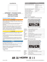
Item Description
ÀFuse
Á12 Vdc power source
ÂCommand Link Plus® and Helm Master® bus network connector
ÃDifferential NMEA® 0183 Connection Considerations, page 3
Ä2.4 m (7.9 ft.) no extension
Item Description
ÀSplice
Á• 10 AWG (5.26 mm²) extension wire, up to 4.6 m (15 ft.)
• 8 AWG (8.36 mm²) extension wire, up to 7 m (23 ft.)
• 6 AWG (13.29 mm²) extension wire, up to 11 m (36 ft.)
ÂFuse
Ã20.3 cm (8 in.)
Ä12 Vdc power source
Å2.4 m (7.9 ft.)
ÆDifferential NMEA® 0183 Connection Considerations, page 3
ÇCommand Link Plus and Helm Master bus network connector
2

Command Link Plus and Helm Master Bus Network
Connection Considerations
NOTICE
If you have an existing engine network on your boat, it should
already be connected to power.
This display connects to the Command Link Plus or Helm
Master engine network on your boat to read data from
compatible devices such as certain engines. The engine
network follows a standard and uses proprietary messages.
The Furukawa connector on the end of the power cable
connects the display to the existing engine network, using the
appropriate length pigtail bus wire. You must route the cable
within 6 m (20 ft.) of the engine network backbone.
For more information on connecting to your engine network, see
the engine documentation.
NMEA 2000® Considerations
NOTICE
If you are installing a NMEA 2000 power cable, you must
connect it to the boat ignition switch or through another in-line
switch. NMEA 2000 devices will drain your battery if the NMEA
2000 power cable is connected to the battery directly.
NOTE: If you are connecting this device to an existing NMEA
2000 network, the NMEA 2000 network should already be
connected to power.
If you are connecting this device to an existing NMEA 2000
network by another manufacturer, you should install a NMEA
2000 Power Isolator (010-11580-00) between the existing
network and this device.
This device can connect to a NMEA 2000 network on your boat
to share data from NMEA 2000 compatible devices such as a
GPS antenna or a VHF radio. If you do not have an existing
NMEA 2000 network, you can create a basic one. For more
information, go to www.nmea.org.
The port labeled NMEA 2000 is used to connect the device to a
standard NMEA 2000 network.
Item Description
ÀCL7 display
ÁGPS antenna
ÂIgnition or in-line switch
ÃNMEA 2000 power cable
ÄNMEA 2000 drop cable
Å12 Vdc power source
ÆNMEA 2000 terminator or backbone cable
ÇNMEA 2000 T-connector
ÈNMEA 2000 terminator or backbone cable
Garmin Marine Network Considerations
NOTICE
A Garmin Power over Ethernet (PoE) Isolation Coupler (P/N
010-10580-10) must be used when connecting any third-party
device, such as a FLIR® camera, to a Garmin Marine Network.
Connecting a PoE device directly to a Garmin Marine Network
chartplotter damages the Garmin chartplotter and may damage
the PoE device. Connecting any third-party device directly to a
Garmin Marine Network chartplotter will cause abnormal
behavior on the Garmin devices, including the devices not
properly turning off or the software becoming inoperable.
This device can connect to additional Garmin Marine Network
devices to share data such as radar, sonar, and detailed
mapping. When connecting Garmin Marine Network devices to
this device, observe these considerations.
• All devices connected to the Garmin Marine Network must be
connected to the same ground.
• A Garmin Marine Network cable must be used for all Garmin
Marine Network connections.
◦ Third-party CAT5 cable and RJ45 connectors must not be
used for Garmin Marine Network connections.
◦ Additional Garmin Marine Network cables and connectors
are available from your Garmin dealer.
• The ETHERNET ports on the device each act as a network
switch. Any compatible device can be connected to any
ETHERNET port to share data with all devices on the boat
connected by a Garmin Marine Network cable.
Differential NMEA® 0183 Connection Considerations
This device can receive differential NMEA 0183 information from
a compatible device.
• See the installation instructions for the NMEA 0183 device to
identify the wires.
• See the table and wiring diagram when connecting the data
cable to NMEA 0183 devices.
• You must use 28 AWG, shielded, twisted-pair wiring for
extended runs of wire. Solder all connections and seal them
with heat-shrink tubing.
• See Differential NMEA 0183 Receive Information, page 4
for a list of NMEA 0183 sentences that can be received by
this device.
• The internal NMEA 0183 ports and communication protocols
are configured on the connected display. See the NMEA
0183 section of the display owner's manual for more
information.
• Do not connect either NMEA 0183 data wire from this device
to power ground.
• The power cable from this device and the NMEA 0183 device
must be connected to a common power ground.
ÀN0183+, white
ÁN0183-, blue
ÂNMEA 0183 device
Tank Level Sensor Connection Considerations
You can connect up to six tank level sensors to the device.
NOTICE
You must connect fuel sensors to inputs 1, 2, 3, or 4. If you
connect a fuel sensor to input 5 or 6, the fuel management
system will not working properly.
3

Wire Color Description
Pink Input 1
Black/Pink Ground 1
Green Input 2
Black/Green Ground 2
Brown Input 3
Black/Brown Ground 3
Orange Input 4
Black/Orange Ground 4
Blue Input 5
Back/Blue Ground 5
Yellow Input 6
Black/Yellow Ground 6
Composite Video Considerations
This chartplotter allows video input from composite video
sources using the port labeled CVBS IN. When connecting
composite video, you should observe these considerations.
• The CVBS IN port uses a BNC connector. You can use a
BNC to RCA adapter to connect a composite-video source
with RCA connectors to the CVBS IN port.
• Video is shared across the Garmin Marine Network, but it is
not shared across the NMEA 2000 network.
Specifications
Dimensions (W × H × D) 22.2 × 14.2 × 6.1 cm (8.75 × 5.6 ×
2.6 in.)
Weight 1.13 kg (2.5 lbs)
Display size (W × H) 15.5 × 8.6 cm (6.1 × 3.4 in.)
Display type WVGA display
Material Die-cast aluminum and polycarbonate
plastic
Water rating1IEC 60529 IPX7
Temperature range From -15° to 55°C (from 5° to 131°F)
Input voltage From 10 to 32 Vdc
Typical current draw at 12 Vdc 1.5 A
Max. power usage at 10 Vdc 24 W
Max. current draw at 12 Vdc 2.0 A
Fuse 6 A, 125 V fast-acting
NMEA 2000 LEN 2
NMEA 2000 Draw 75 mA max.
Compass-safe distance 80 cm (31.5 in.)
Wireless frequency and
protocols
Wi‑Fi®, ANT®, and Bluetooth®
technologies
2.4 GHz @ 19.5 dBm nominal
Memory card 2 microSD® card slots; 32 GB max.
card size
1The device withstands incidental exposure to water of up to 1 m
for up to 30 min. For more information go to www.garmin.com
/waterrating.
2Dependent upon the transducer.
3Dependent upon the transducer rating and depth.
4Dependent upon the transducer, water salinity, bottom type,
and other water conditions.
Differential NMEA 0183 Receive Information
Sentence Description
DPT Depth
DBT Depth below transducer
MTW Water temperature
VHW Water speed and heading
WPL Waypoint location
DSC Digital selective calling information
DSE Expanded digital selective calling
HDG Heading, deviation, and variation
HDM Heading, magnetic
MWD Wind direction and speed
MDA Meteorological composite
MWV Wind speed and angle
VDM AIS VHF data-link message
You can purchase complete information about National Marine
Electronics Association (NMEA) format and sentences from
www.nmea.org.
© 2017–2018 YAMAHA Motor Co., LTD or its
subsidiaries
Yamaha®, the Yamaha logo, Command Link Plus®,
and Helm Master® are trademarks of the YAMAHA
Motor Co., LTD.
Garmin® is a trademark of Garmin Ltd. or its
subsidiaries, registered in the USA and other
countries. This trademark may not be used
without the express permission of Garmin.
NMEA®, NMEA 2000®, and the NMEA 2000 logo
are registered trademarks of the National Marine
Electronics Association.
All other trademarks and copyrights are the
property of their respective owners.
/