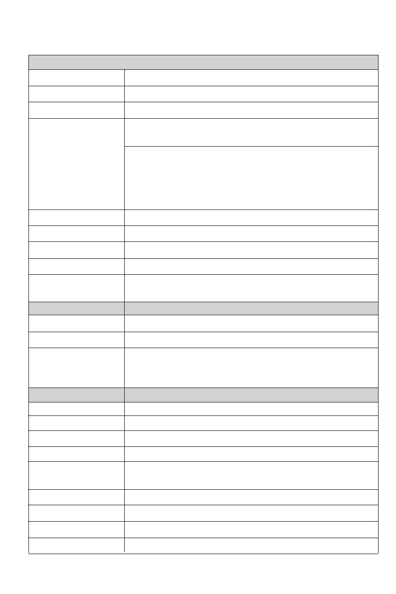
infobit iMatrix User manual

Type
User manual

infobit iMatrix is a versatile 4K60 4x4 HDMI matrix that allows seamless video switching and supports a variety of video wall configurations. With its advanced features and multiple control options, it's ideal for various applications such as home theaters, conference rooms, and digital signage systems. You can effortlessly switch between four HDMI inputs to four outputs, upscale or downscale the resolution to match your display, and transmit audio formats like Dolby TrueHD and DTS-HD Master Audio.

infobit iMatrix is a versatile 4K60 4x4 HDMI matrix that allows seamless video switching and supports a variety of video wall configurations. With its advanced features and multiple control options, it's ideal for various applications such as home theaters, conference rooms, and digital signage systems. You can effortlessly switch between four HDMI inputs to four outputs, upscale or downscale the resolution to match your display, and transmit audio formats like Dolby TrueHD and DTS-HD Master Audio.

VER 1.0
4K60 4x4 Seamless Matrix
iMatrix H44HW
www.infobitav.com info@infobitav.com
Thank you for purchasing this product
Surge protection device recommended
Table of Contents
For optimum performance and safety, please read these instructions carefully before connecting,
operating or adjusting this product. Please keep this manual for future reference.
This product contains sensitive electrical components that may be damaged by electrical
spikes, surges, electric shock, lighting strikes, etc. Use of surge protection systems is highly
recommended in order to protect and extend the life of your equipment.
1. Introduction.....................................................................................................................
2. Features...........................................................................................................................
3. Package Contents........................................................................................................
4. Specifications................................................................................................................
5. Operation Controls and Functions..............................................................................
5.1. Front Panel............................................................................................................
5.2. Rear Panel..............................................................................................................
6. IR Remote......................................................................................................................
7. IR Pin Definition..............................................................................................................
8. EDID Management........................................................................................................
9. Video wall......................................................................................................................
10. Web GUI User Guide...................................................................................................
11. RS-232 Control Command...........................................................................................
12. Application Example...................................................................................................
1
1
1
2
3
3
3
4
5
6
7
7
13
19
1. Introduction
Compliant HDMI 2.0b
Compliant HDCP 2.2 and HDCP 1.4
Features 2 operational modes:
- 4×4 Matrix (seamless switch)
- Video wall (2×2, 4×1 or 1×4 etc configuration)
Seamless video switching
Video inputs support all industry standard video resolutions including VGA-WUXGA (up to
1920×1200 @60Hz) and 480i-4K (3840 x 2160 @60Hz 4:4:4, 4096 x 2160 @60Hz 4:4:4)
HDMI outputs support upscale or downscale to any resolution, up to 4096 x 2160@60Hz
4:4:4
Support LPCM, DD, DD+, DTS, Dolby TrueHD, DTS HD-master pass-through
Advanced EDID management
Web interface module for control and configuration of Matrix
Control via front panel, IR, RS-232 and TCP/IP
3rd Party drivers available for all major home control brands
2. Features
3. Package Contents
1 x 18Gbps 4x4 Seamless Matrix
1 x Matrix IR Remote
1 x 3pin-3.81mm Phoenix Connector (male)
1 x 38KHz IR Wideband Receiver Cable (1.5 meters)
2 x Mounting Ears
4 x Machine Screws (KM3*4)
1 x 12V/2.5A Locking Power Adapter
1x User Manual
- 1 / 19 -
The 4K60 4:4:4 HDMI matrix is a multi-purpose high-speed video processing system. It can
be configured for 2 different output modes. It can perform as a 4×4 seamless matrix switcher,
as a 2×2, 4×1 or 1×4 etc video wall solution. It also features a web browser interface module
for control and configuration of the matrix when used stand-alone or with a third party control
system. Control options include front-panel push buttons, IR remote control, RS-232
interface and TCP/IP.
Color
Mechanical
Housing Metal Enclosure
Black
Dimensions 270mm (W) × 166mm (D) × 30mm (H)
Weight 1165g
Power Supply Input: AC 100 - 240V 50/60Hz
Output: DC 12V/2.5A (US/EU standard, CE/FCC/UL certified)
Power Consumption 19.56W (Max)
0°C ~ 40°C / 32°F ~ 104°F
-20°C ~ 60°C / -4°F ~ 140°F
Operating Temperature
Storage Temperature
Relative Humidity 20~90% RH (non-condensing)
Connection
- 2 / 19 -
4. Specifications
Technical
HDCP Compliance HDCP 2.2/1.4
Video Bandwidth 594MHz/18Gbps
Video Resolution
Input: VGA-WUXGA (up to 1920×1200@60Hz), 480i-4K
(3840x2160@60Hz 4:4:4, 4096x2160@60Hz 4:4:4)
Output: 4096x2160p60, 4096x2160p50, 3840x2160p60,
3840x2160p50, 3840x2160p30, 1920x1080p60,
1920x1080p50, 1920x1080i60, 1920x1080i50,
1920x1200p60rb, 1360x768p60, 1280x800p60,
1280x720p60, 1280x720p50, 1024x768p60, auto
Color Space RGB, YCbCr 4:4:4/4:2:2, YUV 4:2:0
Color Depth 8/10/12-bit
HDMI Audio Formats LPCM, Dolby Digital/Plus/EX, Dolby True HD, DTS, DTS-EX,
DTS-96/24, DTS High Res, DTS-HD Master Audio
HDMI Compliance HDMI 2.0b
IR Level 12Vp-p
IR Frequency 38KHz
Outputs
Inputs
4 × HDMI Type A [19-pin female]
Control
1 × RS-232 [3pin-3.81mm phoenix connector]
1 × TCP/IP [RJ45]
1 × IR EXT [3.5mm Stereo Mini-jack]
4 x HDMI Type A [19-pin female]
- 3 / 19 -
5. Operation Controls and Functions
4
No. Name Function Description
1Power button
2
▪ Short press this button to power on the device.
▪ Press this button for 1 seconds to enter the standby mode.
3
Signal source
LED Signal source indicator for the OUT 1 - OUT 4 port.4
IR Window IR receiver window, it only receives the IR remote signal from this
product.
Power LED The LED will illuminate in green when the product is working
normally, and red when the product is on standby.
5
Input source
switching
button
Input source switching button for the OUT 1- OUT 4 port.
IR
1 2 3 4
OUT 1
1 2 3 4
OUT 2
1 2 3 4
OUT 3
1 2 3 4
OUT 4
1 2 3 5 55 54 4 4 4
5.1 Front Panel
DC 12VIR EXTRS-232
RXTX
HD 1 HD 2 HD 3 HD 4
OUTPUT
HD 1 HD 2 HD 3 HD 4
INPUT
TCP/IP
12364 5
4
3
HDMI INPUT HDMI signal input port, connected to signal source device
4
DC 12V DC 12V/2.5A power input port.6
IR EXT
If the IR receiver window of the unit is blocked or the unit is installed
in a closed area out of infrared line of sight, the IR receiver cable
can be inserted to the “IR EXT” port to receive the IR remote signal.
5 HDMI OUTPUT HDMI signal output port, connected to HDMI display device.
No. Name Function Description
1 TCP/IP
2
The link port for TCP/IP control, connected to an active Ethernet
link with an RJ45 cable to control the Matrix via Web.
RS-232 RS-232 serial command control port, connected to a PC or control
system to control the Matrix.
5.2 Rear Panel
- 4 / 19 -
6. IR Remote
Power on or Standby: Power on the Matrix or set it to standby mode.
INFO: Press this button to display the serial port baud rate and IP address in the upper
right corner of the screen. (The information will disappear after 5 seconds.)
INPUT/OUTPUT
INPUT 1/2/3/4: Select the signal input channel.
: Select the last or next signal input channel.
OUTPUT 1/2/3/4: Select the signal output channel.
ALL: Select all output channels simultaneously. For example, when you press the “ALL”
button and then press INPUT “1” button, at this time the input “1” source will be
output to all display devices.
Res: Press this button to switch output channel resolution.
Matrix mode: Press OUTPUT 1/2/3/4 or ALL, then press Res to switch the output
resolution circularly.
Video wall mode: Press Res directly to switch the output resolution for four output
channels simultaneously.
Operation Instruction: You need to press the OUTPUT button firstly and then press the
INPUT button to select the corresponding input source. For example,
Press OUTPUT-X (X means output button from 1 to 4, including “ALL” button), then
press INPUT-Y (Y means input button from 1 to 4).
VIDEO WALL:
Video wall mode selection:
Press the video wall mode button directly to enter corresponding mode.
Source selection for the video wall group:
Press OUTPUT 1/2/3/4 or / to select the video wall group firstly, then press
INPUT 1/2/3/4 or / to select the input source.
Bezel Adjustment: Press / of H-BEZEL / V-BEZEL to adjust the bezel.
1
3
2
4
- 5 / 19 -
7. IR Pin Definition
IR Receiver pin’s definition is as below:
Note: When the angle between the IR receiver and the remote control is ± 45 °, the
transmission distance is 0-5 meters; when the angle between the IR receiver and the
remote control is ± 90 °, the transmission distance is 0-8 meters.
IR RECEIVER
Power 12V
IR Signal
Grounding
IR RECEIVER
- 6 / 19 -
EDID Mode EDID Description
1 4k2k60_444,stereo audio 2.0
2
3
4
5
6
7
4k2k60_444,dolby/dts 5.1
4k2k60_444,hd audio 7.1
4k2k30_444,stereo audio 2.0
4k2k30_444,hd audio 7.1
4k2k30_444,dolby/dts 5.1
8
9
1080p,stereo audio 2.0
1080p,dolby/dts 5.1
1080p,hd audio 7.1
10
11
12
13
14
15
16
17
18
1920x1200,stereo audio 2.0
1360x768, stereo audio 2.0
1024x768, stereo audio 2.0
user define1
user define2
copy from hdmi output 1
copy from hdmi output 2
copy from hdmi output 3
copy from hdmi output 4
8. EDID Management
This Matrix has 12 factory defined EDID settings, 2 user-defined EDID modes and 4 copy EDID
modes. You can select defined EDID mode or copy EDID mode to input port through RS-232
control or Web GUI.
RS-232 control operation: Connect the Matrix to PC with a serial cable, then open a Serial
Command tool on PC to send ASCII command “s edid in x from z!” to set EDID. For details,
please refer to “EDID Setting” in the ASCII command list of “11. RS-232 Control Command”.
Web GUI Operation: Please check the EDID management in the “Input page” of “10. Web
GUI User Guide”.
The defined EDID setting list of the product is shown as below:
- 7 / 19 -
The matrix supports 10 categories of display modes as below:
User can select display modes via IR remote, Web GUI or RS-232 commands.
10. Web GUI User Guide
The Matrix can be controlled by Web GUI. The operation method is shown as below:
Step 1: Get the current IP Address.
The default IP address is 192.168.0.100. You can get the current Matrix IP address in two ways:
The first way:
You can get the IP address via remote controller. Press “INFO” button, the IP
address will show the upper right corner of the screen.
The second way:
You can get the IP address via RS-232 control Send the ASCII command
“ r ip addr!” through a Serial Command tool, then you’ll get the feedback information as shown
below:
IP:192.168.0.100 in the above figure is the current Matrix IP address (this IP address is
variable, depending on what the specific machine returns).
For the details of RS-232 control, please refer to “11. RS-232 Control Command”.
PC
Step 2: Connect the TCP/IP port of the Matrix to a PC with an UTP cable (as shown in the
following figure), and set the IP address of the PC to be in the same network segment with
the Matrix.
9. Video Wall
Group 1 AA
B
Matrix
2x2
1x3 3x1 4x1
1x4
2x1-2 2x1 1x2-2 1x2
Group 2
Group 3
Group 4
- 8 / 19 -
After entering the Web GUI page, there will be a Login page, as shown below:
Select the Username from the drop-down list and enter the password. The default
passwords are:
Username User Admin
Password user admin
Select the Language from the drop-down list to choose English or Simple Chinese.
After entering the password, click the “LOGIN” button and the following Status page will
appear.
■ Status Page
The Status page provides basic information about the product model, installed firmware
version and the network settings of the device.
Step 3: Input the current IP address of Matrix into your browser on the PC to enter Web GUI
page.
- 9 / 19 -
■ Input Page
You can do the following operations on the Input page:
Inputs: Input channel of the device.
Active: It indicates whether the channel is connected to a signal source. When the input
port is connected to the signal, it shows green, otherwise, it shows gray.
Name: The input channel’s name. You can modify it by entering the corresponding name
(max length: 31 characters for English and 15 characters for Chinese) in the input box.
Chinese name is unsupported when the language is English; and when the language is
Chinese, both English and Chinese name are available.
EDID: You can set the current channel’s EDID. Click drop-down list to select.
Load EDID to user memory: Set EDID for the User.
Click the “Browse” button, then select the bin file. If you select the wrong EDID file, there will
be a prompt, as shown in the following figure:
Make sure to select the correct file, then you can check the name of the selected file. Select
“User 1” or “User 2”, then click “Upload”. After successful setting, it will prompt as follows:
Download EDID to your computer:
Click the drop-down box of “Select EDID File” to select the corresponding input channel. Then
click “Download” to download the corresponding EDID file.
- 10 / 19 -
■ Video Mode Page
■ Output Page
You can do the following operations on the Output page:
Outputs: Output channel of the device.
Cable: It indicates the connection status of output ports. When the output port is connected
to the display, it shows green, otherwise, it shows gray.
Name: The current output channel’s name. You can modify it by entering the corresponding
name (max length: 12 characters) in the input box. Chinese name is unsupported when the
language is English; and when the language is Chinese, both English and Chinese name are
available.
Output Resolution: Set the current output resolution mode. Click the drop-down list to select.
HDCP: The HDCP version that the current output port supports. Click the drop-down list
to select.
Stream: Turn on/off the output stream.
Note: User cannot set each output resolution separately in video wall mode.
You can do the following operations on the Video page:
Matrix: Click to select matrix mode.
Video Wall: Click to select any multiview display mode.
Video Wall Adjustment: Display the input and output information.
Input Source: Three methods to select the input source:
Method 1: Drag Input1/2/3/4/Pattern to any box of Video Wall Adjustment.
Method 2: Select any box in Video Wall Adjustment, then click Input1/2/3/4/Pattern in
Input Source.
Method 3: Click / to select the last or next signal source.
Bezel Adjustment: Click +/- to adjust the corresponding Horizontal/Vertical Bezel
(Up to 10 levels).
Output Resolution: Set the resolution of all current output ports. Click the drop-down list
to select.
- 11 / 19 -
Modify User Password
Click the “User” button, enter the correct Old Password, New Password, and Confirm
Password, then click “Save”. After successful modification, there will be a prompt, as shown
in the following figure:
Note: Input rules for changing passwords:
(1) The password can’t be empty.
(2) New Password can’t be the same as Old Password.
(3) New Password and Confirm Password must be the same.
■ Network Page
You can do the following operations on the Network page:
Modify Network Setting
Modify the IP Mode Address/Gateway/Subnet Mask/Telnet Port as required, click “Save”
to save the settings, then it will come into effect.
After modification, if the Mode is “Static”, it will switch to the corresponding IP Address;
if the Mode is “DHCP”, it will automatically search and switch to the IP Address assigned
by the router.
- 12/ 19 -
Click “OK” to search the IP Address again, as shown in the following figure:
After searching is completed, it will switch to the login page, the default network setting is
completed.
■ System Page
Set the Default Network
Click “Set Network Defaults” button, there will be a prompt, as shown in the following figure:
- 13 / 19 -
Then open a Serial Command tool on PC to send ASCII commands to control the product.
The ASCII command list about the product is shown as below.
11. RS-232 Control Command
ASCII Command
Serial port protocol: Baud rate: 115200(default) Data bits: 8 Stop bits: 1 Check bit: 0
x - Parameter 1
y - Parameter 2
! - Delimiter
Command Code Function Description Feedback Default Setting
System setting
help! Lists all commands
r status! Get device current status
get the unit all status:
power, beep, lock, in /
out connection, video/
audio crosspoint, edid,
scaler, network status
r type! Get device model 4x4 hdmi seamless
matrix
Example
help!
r status!
r type!
Panel Lock: Click to lock/unlock panel buttons. “ON” indicates that panel buttons are
unavailable; “OFF” indicates panel buttons are available.
Beep: Click to turn on/off the beep.
Pattern: Click to select 6 patterns.
Serial Baud Rate: Click the value to set the Serial Baud Rate.
Firmware Update: Click “Browse” to select the update file, then click “Update” to complete
firmware update.
Factory Reset: You can reset the machine to factory defaults by clicking “Reset”.
Reboot: You can reboot the machine by clicking “Reboot”.
Note: After reset/reboot, it will switch to the login page.
You can do the following operations on the System page:
The product also supports RS-232 command control. Connect the RS-232 port of the
product to a PC with a 3-pin phoenix connector cable. The connection method is as follows.
RS-232 to USB cable
TX
Ground
RX
3-pin Phoenix Connector
RS-232
PC
- 14 / 19 -
r fw version! Get firmware version mcu fw version x.xx.xx
s power z! Power on/off the device,z=0~1
(z=0 power off, z=1 power on)
power on
system initializing...
initialization finished!
mcu fw version x.xx.xx
r power! Get current power state power on /power off 3840x2160p60
r fw version!
s power 1!
r power!
s beep z! Enable/disable buzzer function,
z=0~1(z=0 beep off, z=1 beep on)
beep on
beep off beep on
beep on
panel button
lock off
s beep 1!
r beep! Get buzzer state beep on / beep off
r beep!
s lock z! Lock/unlock front panel button,
z=0~1(z=0 lock off,z=1 lock on)
panel button lock on
panel button lock off
s lock 1!
r lock! Get panel button lock state panel button lock on/offr lock!
s reset! Reset to factory defaults
reset to factory defaults
system initializing...
initialization finished!
mcu fw version x.xx.xx
s reset!
s reboot! Reboot the device
reboot…
system initializing...
initialization finished!
mcu fw version x.xx.xx
s reboot!
Command Code Function Description Feedback Default Setting
Example
Output setting
s in x av out y! Set input x to output y x=1~4
y=0~4(0=all) input 1 -> output 2 ptp
r av out y! Get output y signal status
y=0~4(0=all)
input 1 -> output 1
input 2 -> output 2
……
input 4 -> output 4
s output y res x!
Set output y resolution
(y=0~4, x=1~16)
y=0. output all
y=1. output 1
y=2. output 2
y=3. output 3
y=4. output 4
1. 4096x2160p60,
2. 4096x2160p50,
3. 3840x2160p60,
4. 3840x2160p50,
5. 3840x2160p30,
6. 1920x1080p60,
7. 1920x1080p50,
8. 1920x1080i60,
9.1920x1080i50,
10. 1920x1200p60rb,
11.1360x768p60,
12.1280x800p60,
13.1280x720p60,
14.1280x720p50,
15.1024x768p60,
16. auto
output 1 resolution:
3840x2160p60 3840x2160p60
s in 1 av out 2!
r av out 0!
s output 1 res 3!
- 15 / 19 -
Command Code Function Description Feedback Default Setting
Example
r output y csc!
Get output y color space status.
(y=0~4)
y=0. output all
y=1. output 1
y=2. output 2
y=3. output 3
y=4. output 4
output 1 csc: rgb444r output 1 csc!
s output y csc x!
Set output y color space
(y=0~4, x=1~4)
y=0. output all
y=1. output 1
y=2. output 2
y=3. output 3
y=4. output 4
x=1. rgb444
x=2. ycbcr444
x=3. ycbcr422
x=4. ycbcr420
output 1 csc: rgb444
r output y res!
Get output y resolution(y=0~4)
y=0. output all
y=1. output 1
y=2. output 2
y=3. output 3
y=4. output 4
output 1 resolution:
3840x2160p60
s output 1 csc 1!
s output 1 csc 1! rgb444
s output y hdcp x!
Set output hdcp(y=0~4, x=1~5)
y=0. output all
y=1. output 1
y=2. output 2
y=3. output 3
y=4. output 4
x=1. hdcp 1.4
x=2. hdcp 2.2
x=3. follow sink
x=4. follow source
output 1 hdcp:
hdcp 1.4 hdcp1.4
s output 1 hdcp 1!
enable
r output y hdcp!
Get output y hdcp status.(y=0~4)
y=0. output all
y=1. output 1
y=2. output 2
y=3. output 3
y=4. output 4
output 1 hdcp:
hdcp 1.4
r output 1 hdcp!
s output y stream
x!
Set output y stream enable/disable
(y=0~4, x=0~1)
y=0. output all
y=1. output 1
y=2. output 2
y=3. output 3
y=4. output 4
x=0. stream disable
x=1. stream enable
output 1 stream: enable
s output 1
stream 1!
- 16 / 19 -
r output y stream!
Get output y stream status.
(y=0~4)
y=0. output all
y=1. output 1
y=2. output 2
y=3. output 3
y=4. output 4
output 1 stream: enabler output 1 stream!
EDID setting
r output bg! Get output no signal background
display mode
output background:
black screen
r output bg!
s edid in x from z!
Set hdmi input x edid mode
(x=0~4,z=1~18)
x=0. all input
x=1. input1
x=2. input2
x=3. input3
x=4. input4
z=1. 4k2k60_444,stereo audio 2.0
z=2. 4k2k60_444,dolby/dts 5.1
z=3. 4k2k60_444,hd audio 7.1
z=4. 4k2k30_444,stereo audio 2.0
z=5. 4k2k30_444,dolby/dts 5.1
z=6. 4k2k30_444,hd audio 7.1
z=7. 1080p,stereo audio 2.0
z=8. 1080p,dolby/dts 5.1
z=9. 1080p,hd audio 7.1
z=10.1920x1200,stereo audio 2.0
z=11.1360x768, stereo audio 2.0
z=12.1024x768, stereo audio 2.0
z=13.user define1
z=14.user define2
z=15.copy from hdmi output 1
z=16.copy from hdmi output 2
z=17.copy from hdmi output 3
z=18.copy from hdmi output 4
output background:
black screen
r output bg!
s output bg x!
Set output no signal background
display mode (x=1~6)
x=1. black screen
x=2. blue screen
x=3. color bar
x=4. gray scale
x=5. cross
x=6. cross hatch
output background:
black screen
r edid in x!
Get input x edid mode(x=0~4)
x=0. all input
x=1. input1
x=2. input2
x=3. input3
x=4. input4
input 1 edid: 4k2k60_444,
stereo audio 2.0
input 2 edid: 4k2k60_444,
stereo audio 2.0
input 3 edid: 4k2k60_444,
stereo audio 2.0
input 4 edid: 4k2k60_444,
stereo audio 2.0
r edid in 0!
s output bg 1! black screen
Command Code Function Description Feedback Default Setting
Example
- 17 / 19 -
Command Code Function Description Feedback Default Setting
s tw mode x!
Set tv wall display mode(x=1~10)
x=1. 2x2 mode
x=2. 2x1 mode
x=3. 2x1-2 mode
x=4. 1x2 mode
x=5. 1x2-2 mode
x=6. 3x1 mode
x=7. 4x1 mode
x=8. 1x3 mode
x=9. 1x4 mode
x=10. matrix mode
tv wall mode: 2x2 tv wall mode: 2x2
r tw mode! Get tv wall display mode
s tw h bezel x! set tv wall horizontal bezel
(x=0~10,+,-)
tv wall mode: 2x2
tv wall horizontal
bezel: 0
hdmi all oumode
tv wall horizontal
bezel: 0
r tw h bezel! Get tv wall row bezel
s tw v bezel x! Set tv wall vertical bezel
(x=0~10,+,-) tv wall vertical bezel: 0
tv wall horizontal
bezel: 0
s tw group y i
nput x!
Set tv wall group y display which
source input(y=0~4, x=1~4)
y=0. tv wall group all
y=1. tv wall group 1
y=2. tv wall group 2
y=3. tv wall group 3
y=4. tv wall group 4
x=1. hdmi input 1
x=2. hdmi input 2
x=3. hdmi input 3
x=4. hdmi input 4
tv wall group 1 input:
hdmi input 1
tv wall group 1
input: hdmi input 1
3840x2160p60
3840x2160p60
Example
s tw mode 1!
r tw mode!
r tw v bezel! Get tv wall vertical bezel tv wall vertical bezel: 0 hdmi all oumode r tw v bezel!
s tw h bezel 0!
r tw h bezel!
s tw v bezel 0!
s tw group 1
input 1!
r tw group y
source!
Get tv wall group y display which
source input(y=0~4)
y=0. tv wall group all
y=1. tv wall group 1
y=2. tv wall group 2
y=3. tv wall group 3
y=4. tv wall group 4
tv wall group 1 input:
hdmi input 1
tv wall group 2 input:
hdmi input 2
tv wall group 3 input:
hdmi input 3
tv wall group 4 input:
hdmi input 4
r tw group 0
source!
s tw res x!
Set tv wall resolution (x=1~15)
1. 4096x2160p60,
2. 4096x2160p50,
3. 3840x2160p60,
4. 3840x2160p50,
5. 3840x2160p30,
6. 1920x1080p60,
7. 1920x1080p50,
8. 1920x1080i60,
9.1920x1080i50,
10. 1920x1200p60rb,
11.1360x768p60,
12.1280x800p60,
13.1280x720p60,
14.1280x720p50,
15.1024x768p60,
tv wall resolution:
3840x2160p60
s tw res 3!
r tw res! Get tv wall resolution tv wall resolution:
3840x2160p60
r tw res!
Video wall setting
Command Code Function Description Feedback Default Setting
r ipconfig! Get the current ip configauration
ip mode: static
ip: 192.168.0.100
subnet mask:
255.255.255.0
gateway: 192.168.0.1
tcp/ip port=8000
telnet port=23
mac address:
00:1c:91:03:80:01
r mac addr! Get network mac address
s ip mode z! Set network ip mode to static ip or
dhcp,z=0~1 (z=0 static, z=1 dhcp)
mac address:
00:1c:91:03:80:01
set ip mode:static.
(please use "s net
reboot!" command or
repower device to
apply new config!)
r ip mode! Get network ip mode
s ip addr
xxx.xxx.xxx.xxx! Set network ip address
set ip address:
192.168.0.100
(please use "s net
reboot!" command or
repower device to
apply new config!)
dhcp on, device can't
config static address,
set dhcp off first.
ip mode: static
r ip addr! Get network ip address ip address:
192.168.0.100
Example
r ipconfig !
r mac addr!
s ip mode 0!
r ip mode!
s ip addr
192.168.0.100!
r ip addr!
s subnet
xxx.xxx.xxx.xxx! Set network subnet mask
set subnet mask:
255.255.255.0
(please use "s net
reboot!" command or
repower device to
apply new config!)
dhcp on, device can't
config subnet mask,
set dhcp off first.
s subnet
255.255.255.0!
r subnet! Get network subnet mask subnet mask:
255.255.255.0
r subnet!
r gateway! Get network gateway gateway:192.168.0.1r gateway!
s tcp/ip port x! Set network tcp/ip port (x=1~65535) set tcp/ip port:8000s tcp/ip port 8000!
r tcp/ip port! Get network tcp/ip port tcp/ip port:8000r tcp/ip port!
s telnet port x! Set network telnet port(x=1~65535) set telnet port:23s telnet port 23!
r telnet port! Get network telnet port telnet port:23r telnet port!
s gateway
xxx.xxx.xxx.xxx! Set network gateway
set gateway:
192.168.0.1
(please use "s net
reboot!" command or
repower device to
apply new config!)
dhcp on, device can't
config gateway, set
dhcp off first.
s gateway
192.168.0.1!
s net reboot! Reboot network modules
network reboot…
ip mode: static
ip: 192.168.0.100
subnet mask:
255.255.255.0
gateway: 192.168.0.1
tcp/ip port=8000
telnet port=10
mac address:
00:1c:91:03:80:01
s net reboot!
Network setting
- 18 / 19 -
  • Page 1 1
  • Page 2 2
  • Page 3 3
  • Page 4 4
  • Page 5 5
  • Page 6 6
  • Page 7 7
  • Page 8 8
  • Page 9 9
  • Page 10 10
  • Page 11 11
  • Page 12 12
  • Page 13 13
  • Page 14 14
  • Page 15 15
  • Page 16 16
  • Page 17 17
  • Page 18 18
  • Page 19 19
  • Page 20 20
  • Page 21 21

infobit iMatrix User manual

Type
User manual

infobit iMatrix is a versatile 4K60 4x4 HDMI matrix that allows seamless video switching and supports a variety of video wall configurations. With its advanced features and multiple control options, it's ideal for various applications such as home theaters, conference rooms, and digital signage systems. You can effortlessly switch between four HDMI inputs to four outputs, upscale or downscale the resolution to match your display, and transmit audio formats like Dolby TrueHD and DTS-HD Master Audio.

Ask a question and I''ll find the answer in the document

Finding information in a document is now easier with AI