Page is loading ...

4-20 mA
Controller/Alarm
Indicator
Model : CT-2012
Your purchase of this 4 to 20 mA CONTROLLER marks a
step forward for you into the field of precision
measurement. Although this METER is a complex and
delicate instrument, its durable structure will allow many
years of use if proper operating techniques are
developed. Please read the following instructions
carefully and always keep this manual within easy reach.
OPERATION MANUAL

Caution Symbol
Caution :
* Risk of electric shock !
Caution :
* Do not use fingers or any tool
to touch the Wire Terminals.
* Do not apply the relay contact load
current > 0.5 Amp.
* The instrument contains no user
serviceable parts and should not
be opened by the user.
* Repair or after service should be
done by a qualified technician only.
* Power supply should apply the
correct ACV power voltage
* Cleaning - Only use the dry cloth to
clean the plastic case !
* Equipment protected throughout
by Double Insulation or Reinforced
Insulation.
Environmental Condition
* Comply with EN61010.
Transient over voltage at Mains Supply 2500V.
* Pollution Degree 2.
* Altitude up to 2000 meters.
* Indoor use.
* Relative humidity 80% max.

TABLE OF CONTENTS
1. FEATURES.........................................................................
1
2. SPECIFICATIONS..................................................................
2
3. FRONT PANEL DESCRIPTION............................................
5
3-1 Display....................................................................
5
3-2 PV ( process value ) indicator............................................
5
3-3 SV ( set value ) indicator............................................
5
3-4 Set Button..............................................................
5
3-5 Button..............................................................▼
5
3-6 Button.............................................................▲ 5
3-7 Control relay indicator........................................... 5
3-8 Alarm relay indicator............................................ 5
3-9 Wire terminals.................................................... 5
3-10 Case holder ....................................................... 5
3-11 RS232 terminal................................................... 5
4. MEASURING PROCEDURE .......................................... 6
4-1 Terminal connection.................................................
6
4-2 1st layer setting procedures......................................
7
a. Control Low limit value setting.............................. 7
b. Control High limit value setting............................ 7
c.
Alarm Low limit value setting...................................
8
d.
Alarm High limit value setting...................................
8
4-3 2nd layer setting procedures......................................
9
a.
Point position setting...............................................
9
b. 4 mA value setting............................................... 9
c.
20 mA value setting................................................
10
d.
Digital filter value setting..........................................
10
e.
Control hysteresis value setting...............................
11
f.
Alarm hysteresis value setting.................................
12
g.
Offset value adjustment...........................................
13
h.
Gain value setting...................................................
13
i.
RS232 output unit code setting..................................
14
5.. RS232 PC SERIAL INTERFACE.....................................................
14
6. SYSTEM RESET......................................................... 17
7. THE ADDRESS OF AFTER SERVICE CENTER......................
17

1. FEATURES
* Input : 4-20 mA DC, linear.
* User can default the desired display value between
-1999 to 9999 ( decimal point can be selected to DP1,
DP2, DP3 ) and all the preset data will be saved into
the memory circuit permanently.
* According the 4 to 20 mA input signal, user can preset
the desire display value between -1999 to 9999 ( decimal
point can select to DP1, DP2, DP3 ). Until set the display
value, all the data will save into the memory circuit
permanently
* When CT-2012 cooperate LUTRON's 4 to 20 mA
transmitters ( or any other transmitters if it build 4 to
20 mA output signal ), whole system will become the
high performance Controller/Alarm/Indicator for
following measuring functions : Humidity, Light, pH,
Dissolved Oxygen, Conductivity, Vibration, Pressure,
Sound, Temperature, RPM, Hz, Load cell ( Weight,
Force ), Potential ( Angle, Level ). ACV, ACA, DCV,
DCA, WATT....
* Easy to adjust the function factors by push button
on the front panel.
* Control output : 2 points ( COM, NO ).
* Alarm output : 2 points ( COM, NO ).
* Control Relay will make action when the reading value
reach to control value.
* Hysteresis value setting for control and alarm function.
* Large red LED display, high brightness and easy to read.
* Microprocessor circuit ensures high accuracy and
provides special functions and features.
* DC 12V power supply output.
* RS232/USB computer interface.
* Power : 90 ACV - 264 ACV, 50/60 Hz.
* Standard 96 X 48 mm DIN case.
* Optional data acquisition software.
1

2. SPECIFICATIONS
Display * 4 digits red LED,
14 mm ( 0.55 inch ) digit height
* 4 indicators :
PV ( process value ) indicator
SV ( set value ) indicator
Control out indicator
Alarm out indicator
* According the 4-20 mA input signal,
user can preset the desire display value
between -1999 to 9999 ( decimal point
can select to DP1, DP2, DP3 ). Until set
the display value, all the data will save
into the memory circuit permanently
Input Signal Linear, 4 to 20 mA
Circuit Custom chip of microprocessor LSI
circuit.
Sampling Time Approx. 1 second.
Relay Output Number 2 relays
Function
Relay 1 :
High/Low control relay.
Relay 2 :
High/Low alarm relay.
Max load 0.5 ACA/250 ACV
0.5 DCA/24 DCV
*
Do not apply the relay
contact load current
> 0.5 A, other wise the
relay may be damaged
permanently without
warranty.
2

* Decimal point adjustment :
DP1, DP2, DP3
Main * Low limit of range adjustment
Internal 4 mA = X X X X, min. value is -1999
Function * High limit of range adjustment
Selection 20 mA = X X X X, max. value is 9999
* Alarm value adjustment :
High Alarm or Low alarm.
* Control value adjustment
High control or Low control.
* Control hysteresis value setting.
* Alarm hysteresis value setting.
* Filter value of display reading
* Offset adjustment.
* Gain adjustment.
* RS232 output unit code setting
Default of internal function :
Without advice previously, the function
of CT-2012 will preset :
* 4 mA = 0, 20 mA = 9999.
* High control mode.
* High alarm mode.
* RS232 output unit code = 0 ( no unit ).
Front Panel * Control set-point value adjustment.
Function * Measuring value ( Process value )
Selection offset. Use to offset the PV indication
from the actual PV.
* Alarm set-point value adjustment.
External DC 12 V, 50 mA max.
Power Supply
Data Output RS 232 PC serial interface.
Operating 0 to 50 .℃
Temperature
Operating Less than 80% R.H.
Humidity
3

Power Supply 90 to 260 ACV, 50/60 Hz.
Power Approx. 3.5 VA/AC 110V.
Consumption Approx. 4.9 VA/AC 220V.
Weight 384 g/ 0.84 LB.
Dimension DIN size : 96 x 48 mm.
Panel cut size : 92 mm x 46 mm.
Depth : 110 mm.
Accessories
Instruction manual..............................
1 PC
Included
Case holder with screw..............................
2 PCs
Optional * Data Acquisition software,
Accessories SW-U801-WIN.
* RS232 cable, UPCB-02.
* USB cable, USB-01.
4

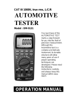
3. FRONT PANEL DESCRIPTION
Fig. 1
3-1 Display
3-2 PV ( process value ) indicator
3-3 SV ( set value ) indicator
3-4 Set Button
3-5 Button▼
3-6 Button▲
3-7 Control relay indicator
3-8 Alarm relay indicator
3-9 Wire terminals
3-10 Case holder
3-11 RS232 terminal
5

4. MEASURING PROCEDURE
4-1 Terminal connection
1)Input the ACV power ( 90 to 260 ACV ) to T1, T2.
Do not input the
over voltage to the
AC input terminals.
2)Connect the " Control Relay " output from T3, T4.
Connect the " Alarm Relay " output from T5, T6.
3)Connect the input signal ( 4 to 20 mA DC ) to
to the input terminal T15 (+), T16 (-).
4)T7 (+), T8 ( - ) are DC 12 V power supply terminal.
If the measured installation ( transmitters ) need the
the external DC 12V power supply, can connect its
power supply from T7, T8.
6

4-2 1st layer setting procedures
CtLo Control Low limit value setting
CtHi Control High limit value setting
ALLo Alarm Low limit value setting
ALHi Alarm High limit value setting
a. Control Low limit value setting
1)Press the " Set Button " ( 3-4, Fig. 1 ) once, the
" Display " will show " CtLo ", now the meter is ready
for the " Control Low limit value " setting.
2)Use the " Button " ( 3-5, Fig. 1 ) and the " ▼ ▲
Button " ( 3-6, Fig. 1 ) to adjust the desiring " Control
Low limit value ", press the " Set Button " ( 3-4, Fig. 1 )
to save the setting value.
Remark :
* During adjust the value, the " SV indicator " ( 3-3, Fig. 1 )
will light.
* The function of " Control Low limit value " setting, refer to
page 11, Fig. 3.
b. Control High limit value setting
1)After finish above " Control Low limit value setting ",
press the " Set Button " ( 3-4, Fig. 1 ) once, the
" Display " will show " CtHi ", now the meter is ready
for the " Control High limit value " setting.
2)Use the " Button " ( 3-5, Fig. 1 ) and the " ▼ ▲
Button " ( 3-6, Fig. 1 ) to adjust the desiring " Control
High limit value ", press the " Set Button " ( 3-4, Fig. 1 )
to save the setting value.
7

Remark :
* When adjust the value, the " SV indicator " ( 3-3, Fig. 1 )
will light.
* The function of " Control High limit value " setting, refer to
page 11, Fig. 3.
c. Alarm Low limit value setting
1)
After finish above " Control High limit value setting ",
press the " Set Button " ( 3-4, Fig. 1 ) once, the
" Display " will show " ALLo ", now the meter is ready
for the " Alarm Low limit value " setting.
2)Use the " Button " ( 3-5, Fig. 1 ) and the " ▼ ▲
Button " ( 3-6, Fig. 1 ) to adjust the desiring " Alarm
Low limit value ", press the " Set Button " ( 3-4, Fig. 1 )
to save the setting value.
Remark :
* When adjust the value, the " SV indicator " ( 3-3, Fig. 1 )
will light.
* The function of " Alarm Low limit value " setting, refer to
page 12, Fig. 4.
d. Alarm High limit value setting
1)After finish above " Alarm Low limit value setting ",
press the " Set Button " ( 3-4, Fig. 1 ) once, the
" Display " will show " ALHi ", now the meter is ready
for the " Alarm High limit value " setting.
2)Use the " Button " ( 3-5, Fig. 1 ) and the " ▼ ▲
Button " ( 3-6, Fig. 1 ) to adjust the desiring " Alarm
High limit value ", press the " Set Button " ( 3-4, Fig. 1 )
to save the setting value.
Remark :
* During adjust the value, the " SV indicator " ( 3-3, Fig. 1 )
will light.
* The function of " Alarm Low limit value " setting, refer to
page 12, Fig. 3.
8

4-3 2nd layer setting procedures
dPSt Point position setting
4-A 4 mA value setting
20-A 20 mA value setting
FiLt Digital filter setting
CtHy Control hysteresis value setting
ALHy Alarm hysteresis value setting
oFSt Offset value setting
GAin Gain value setting
Unit RS232 output unit code setting
a. Point position setting
1)Press the " Set Button " ( 3-4, Fig. 1 ) continuously at
least two seconds, the " Display " will show " dPSt ",
now the meter is ready for the " Point position Setting ".
2)Use the " Button " ( 3-5, Fig. 1 ) and the " Button "▼ ▲
( 3-6, Fig. 1 ) to adjust the desiring " Point position ",
press the " Set Button " ( 3-4, Fig. 1 ) to save the setting
value.
Remark :
* During adjust the value, the " SV indicator " ( 3-3, Fig. 1 )
will light.
b. 4 mA value setting
1)After finish the " Point position ", press the
" Set Button " ( 3-4, Fig. 1 ) once, the " Display "
will show " 4-A ", now the meter is ready for the
" 4 mA value " setting, for example 4 mA input signal
= 0 or other value upon user own requirement.
2)Use the " Button " ( 3-5, Fig. 1 ) and the " Button "▼ ▲
( 3-6, Fig. 1 ) to adjust the desiring " 4 mA value ",
press the " Set Button " ( 3-4, Fig. 1 ) to save the setting
value.
9

Remark :
* During adjust the value, the " SV indicator " ( 3-3, Fig. 1 )
will light.
c. 20 mA value setting
1)After finish the " 4 mA value setting", press the
" Set Button " ( 3-4, Fig. 1 ) once, the " Display "
will show " 20-A ", now the meter is ready for the
" 20 mA value " setting, for example 20 mA input signal
= 100 or other value upon user own requirement.
2)Use the " Button " ( 3-5, Fig. 1 ) and the " Button "▼ ▲
( 3-6, Fig. 1 ) to adjust the desiring " 20 mA value ",
press the " Set Button " ( 3-4, Fig. 1 ) to save the setting
value.
Remark :
* During adjust the 20 mA value, the " SV indicator "
( 3-3, Fig. 1 ) will light.
d. Digital filter value setting
1)After finish the " 20 mA value setting", press the
" Set Button " ( 3-4, Fig. 1 ) once, the " Display "
will show " FiLt ", now the meter is ready for the
" Digital filter value " setting.
2)Use the " Button " ( 3-5, Fig. 1 ) and the " Button "▼ ▲
( 3-6, Fig. 1 ) to adjust the desiring " Digital filter value ",
press the " Set Button " ( 3-4, Fig. 1 ) to save the setting
value.
Remark :
* During adjust the value, the " SV indicator " ( 3-3, Fig. 1 ) will light,
* The setting range of " Digital filter value " is from 1 to 99.
the default value is 1.
* The more value will get more " Digital filters ", the
Display will be more stable, however the more " Digital
filter value " the response time of Display will be slowly.
10

e. Control hysteresis value setting
1)After finish the " Digital filter value setting ", press
the '" Set Button " ( 3-4, Fig. 1 ) once, the " Display "
will show CtHy ", now the meter is ready for the
" Control Hysteresis value " setting.
2)Use the " Button " ( 3-5, Fig. 1 ) and the " ▼ ▲
Button " ( 3-6, Fig. 1 ) to adjust the desiring
" Control Hysteresis value ", press the " Set Button "
( 3-4, Fig. 1 ) to save the setting value.
Remark :
* During adjust the value " , the " SV indicator " ( 3-3, Fig. 1 )
will light.
* The function of " Control Hysteresis value " setting, refer to
following Fig. 3.
* For example : Fig. 3
Control high limit value ( CtHi ) : 500
Control low limit value ( CtLo ) : 100
Control Hysteresis value ( CtHy ) : 5
a. The control relay will On when measuring value up
to 500. The control relay will Off again when
measuring value down to 495.
b. The control relay will On when measuring value
down to 100. The control relay will Off when
measuring value up to 105.
11

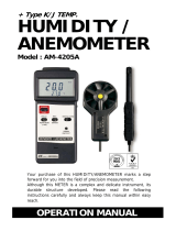
f. Alarm hysteresis value setting
1)After finish the " Control Hysteresis value setting " ,
press the " Set Button " ( 3-4, Fig. 1 ) once, the "
Display " will show " ALHy ", now the meter is ready for
the " Alarm Hysteresis value " setting.
2)Use the " Button " ( 3-5, Fig. 1 ) and the " ▼ ▲
Button " ( 3-6, Fig. 1 ) to adjust the desiring " Alarm
Hysteresis value ", press the " Set Button " ( 3-4, Fig. 1 )
to save the setting value.
Remark :
* During adjust the value " , the " SV indicator " ( 3-3, Fig. 1 )
will light.
* The function of " Alarm Hysteresis value " setting, refer to
following Fig. 4.
Fig. 4
* For example :
Alarm High limit value ( ALHi ) : 100
Alarm Low limit value ( ALLo ) : 20
Alarm Hysteresis value ( ALHy ) : 5
a. The alarm relay will On when measuring value up
to 100. The alarm relay will Off again when
measuring value down to 95.
b. The alarm relay will On when measuring value
down to 20. The alarm relay will Off when
measuring value up to 25.
12

g. Offset value adjustment
1)After finish the " Alarm hysteresis value setting " , press
the " Set Button " ( 3-4, Fig. 1 ) once, the " Display "
will show " oFSt ", now the meter is ready for the "
Offset value adjustment " setting.
2)Use the " Button " ( 3-5, Fig. 1 ) and the " ▼ ▲
Button " ( 3-6, Fig. 1 ) to adjust the desiring
" Offset value ", press the " Set Button " ( 3-4, Fig. 1 )
to save the setting value.
Remark :
* During adjust the value, the " SV indicator " ( 3-3, Fig. 1 )
will light.
h. Gain value setting
1)After finish the " Offset value setting " , press the
" Set Button " ( 3-4, Fig. 1 ) once, the " Display "
will show " oFSt ", now the meter is ready for the
the " Gain value adjustment " setting.
2)Use the " Button " ( 3-5, Fig. 1 ) and the " ▼ ▲
Button " ( 3-6, Fig. 1 ) to adjust the desiring
" Gain value ", press the " Set Button " ( 3-4, Fig. 1 )
to save the setting value.
Remark :
* During adjust the value, the " SV indicator " ( 3-3, Fig. 1 )
will light.
* The Gain value setting range is 0.001 to 9.999, the default value
is 1.000.
13

i. RS232 output unit code setting
1)After finish the " Gain value setting " , press the
" Set Button " ( 3-4, Fig. 1 ) once, the " Display "
will show " Unit ", now the meter is ready for the
the " RS232 output unit code " setting.
2)Use the " Button " ( 3-5, Fig. 1 ) and the " Button "▼ ▲
( 3-6, Fig. 1 ) to adjust the desiring " RS232 output
unit code " no., press the " Set Button " ( 3-4, Fig. 1 ) to
save the setting value.
Remark :
* During adjust the unit code no., the " SV indicator " ( 3-3, Fig. 1 )
will light.
* The RS232 output code list, please refer chapter 5, page 16.
5. RS232 PC SERIAL INTERFACE
The instrument has RS232 PC serial interface via a 3.5
mm terminal ( 3-11, Fig. 1 ).
The data output is a 16 digit stream which can be
utilized for user's specific application.
A RS232 lead with the following connection will be
required to link the instrument with the PC serial port.
Meter PC
(3.5 mm jack plug) (9W 'D" Connector)
Center Pin............................................
Pin 4
Ground/shield...........................................
Pin 2
Pin 5
14

The 16 digits data stream will be displayed in the
following format :
D15 D14 D13 D12 D11 D10 D9 D8 D7 D6 D5 D4 D3 D2 D1 D0
Each digit indicates the following status :
D15 Start Word
D14 4
D13 When send the upper display data = 1
When send the lower display data = 2
D12 & D11 Unit code no., refer to the table, page 16.
D10 Polarity
0 = Positive 1 = Negative
D9 Decimal Point(DP), position from right to the
left
0 = No DP, 1= 1 DP, 2 = 2 DP, 3 = 3 DP
D8 to D1 Display reading, D8 = MSD, D1 = LSD.
For example :
If the display reading is 1234, then D8 to
D1 is : 00001234
D0 End Word
RS232 setting
Baud rate 9600
Parity No parity
Data bit no. 8 Data bits
Stop bit 1 Stop bit
15

The RS232 output code list
00 = NO UNIT 33 = KHz 66 = mF
01 = C 34 = DCV 67 = MHz
02 = F 35 = DCuA 68 = uH
03 = % 36 = DCA 69 = dBm
04 = %RH 37 = DCmA 70 = Red
05 = pH 38 = ohm 71 = Gren
06 = %O2 39 = Kohm 72 = Blue
07 = mg/L 40 = Mohm 73 = Stau
08 = m/s 41 = mH 74 = mSEC
09 = knot 42 = H 75 = uSEC
10 = km/h 43 = nF 76 = SEC
11 = ft/m 44 = uF 77 = Kgc2
12 = ml/h 45 = hfe 78 = mmHg
13 = uS 46 = DIO 79 = mH2O
14 = mS 47 = WATT 80 = inHg
15 = Lux 48 = KWAT 81 = Kgcm
16 = Ftcd 49 = ACmV 82 = Lbin
17 = dB 50 = ACV 83 = N-cm
18 = mV 51 = ACuA 84 = CMM
19 = PPM 52 = ACA 85 = CFM
20 = mg 53 = ACmA 86 = mbar
21 = Tesl 54 = PF 87 = Pa
22 = bar 55 = Kg 88 = kPa
23 = PSI 56 = Lb 89 = uHg
24 = cmHg 57 = gram 90 = Torr
25 = iH2O 58 = oz 91 = hPa
26 = ATP 59 = NewT 92 = m/s2
27 = RPM 60 = m/m 93 = mm/s
28 = in/m 61 = Hour 94 = mm
29 = cm/m 62 = Min 95 = cm/s
30 = COUT 63 = VA 96 = inch
31 = Hz 64 = KVA 97 = FtS2
32 = DEG 65 = KWHr 98 = in/s
16

6. SYSTEM RESET
Power on the meter, use the two fingers to press " Set
Button " ( 3-4, Fig. 1 ) and " Button " ( 3-7,▼
Fig. 1 ) continuously more than 5 seconds until the
Display show the text " rSt ", release the buttons. After
" rSt " text flashing 2 times will return to the normal
screen. The meter system will be reset, all the
calibration data will be cleared, the meter's internal
function will return the default value.
7. THE ADDRESS OF AFTER SERVICE
CENTER
17
0912-CT2012
/