Page is loading ...

Model 37045-Series
QUIET - FLUSH
ELECTRIC TOILET
FEATURES
• Very quiet flush cycle - like a household toilet
• Single button flush actuator - with dual function water
level control switch
• Can be plumbed to any pressurized water system
that can provide a 3-1/2 GPM (13.5 LPM) flow rate
• Water control solenoid valve with anti-siphon breaker
to prevent contamination of potable water supply
• White vitreous china bowl available in compact or
comfortable household size
• Baked enamel seat & cover
• High capacity waste macerator and bowl discharge
pump
SPECIFICATIONS
PORTS Inlet 3/4" Hose Barb
Outlet 1" Hose Barb
MOTOR Meet U.S.C.G. Regulation
& SWITCH 183.410 and ISO 8846 MARINE
for Ignition Protection.
EMC Models Available
WATER 1-2 Quarts (Litres) per Flush
CONSUMPTION
VARIATIONS AVAILABLE
MODEL NO. DESCRIPTION
37045-0012 Compact Size Bowl, 12 Volt DC
37045-0092* Compact Size Bowl, 12 Volt EMC
37045-0024 Compact Size Bowl, 24 Volt DC
37045-0094* Compact Size Bowl, 24 Volt EMC
37045-1012 Household Size Bowl, 12 Volt DC
37045-1092* Household Size Bowl, 12 Volt EMC
37045-1024 Household Size Bowl, 24 Volt DC
37045-1094* Household Size Bowl, 24 Volt EMC
*This model is Marked and complies with EN50081-1 for suppression of
electro-magnetic interference.
OPERATION
The Quiet-Flush toilet provides both quiet operation and
user control of water levels in the toilet bowl. A single
large push button switch provides a simple flush mode
by activating both the rinse water supply and the macer-
ator discharge pump simultaneously. An additional rocker
switch offers independent control of the rinse water supply
and discharge pump separately so the bowl water level
can be easily raised or lowered by the user. This provides
a method of minimizing water use, when desired, as well
as a means of raising the water level in the bowl when
appropriate for user comfort. It also allows for complete
evacuation of the bowl water while underway in rough
sea conditions.
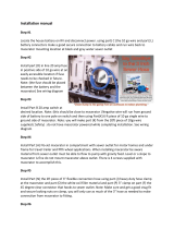
INSTALLATION
PLUMBING
The toilet can be plumbed to any pressurized water system
that can provide a minimum of 3-1/2 GPM (13.5 LPM).
This may be a fresh water system including the vessel’s
potable water system or a washdown system utilizing
either fresh or salt water. However, it must be connected
to a pressurized system that normally remains on at all
times while the vessel is in use.
To make the water connection, shut off the water system
pump and open one of the systems faucets or fixtures to
drain the pressure from the system. Select an appropriate
tee type fitting that can be installed in the existing
pressurized water system and will provide a 1/2"
(13mm) hose barb to feed water to the toilet. Install the
tee fitting at a location on the pressurized water system
that provides convenient connection to the toilet’s
solenoid valve/ siphon breaker assembly. If the toilet is
being connected to the vessel’s fresh water system and
the vessel may be connected to an unregulated city
water supply, it is recommended that a valve be installed
in the toilet water supply line ahead of the solenoid
valve/siphon breaker to regulate the flow rate of
incoming pressurized city water.

INSTALLATION (continued)
PLUMBING
The solenoid valve/siphon breaker should be positioned
a minimum of six inches above the hose connection at
the back of the toilet bowl (at all angles of heel and trim)
and located as close to the toilet as possible. It should be
located where an occasional drop or two of water from
the siphon breaker will not adversely affect nearby
equipment or supplies. It must be installed in a vertical
position with the hose barb connections pointing down.
The solenoid valve/siphon breaker bracket should be
secured to a solid mounting surface with four screws. If
the valve assembly is attached to a wood surface, 3/8"
(10mm) long screws are generally adequate to support
the weight of the valve assembly. If desired, the valve
assembly may be installed inside a cabinet or locker to
conceal it from view of the vessel’s occupants. To
provide a clean sanitary appearance inside the head
area, a six foot section of smooth white hose is provided
with the toilet to connect the toilet bowl spud fitting to the
siphon breaker outlet hose barb.
The solenoid valve inlet hose barb is then connected
with 1/2" (13mm) reinforced vinyl hose suitable for
pressurized water to the tee fitting installed in the water
system line. All pressurized water system connections
should be secured with stainless steel band type hose
clamps. The 3/4" hose connecting the siphon breaker to
the bowl should be secured with a band clamp at the
siphon breaker to prevent it from being accidentally
dislodged but generally does not need a hose clamp to
secure it to the bowl spud fitting unless desired for added
security.
The discharge port includes a 1" (25mm) hose barb and
should be plumbed with 1" (25mm) hose to an on board
holding tank or, if appropriate, to an overboard discharge
through hull. A 1" (25mm) to 1-1/2" (38mm) barbed hose
adapter is provided to adapt a 1" (25mm) discharge hose
to 1-1/2" (38mm) hose, if desired. The discharge plumbing
should be kept as short as possible and bends in the
discharge hose should be kept to a minimum.
If the toilet is below the water line and is plumbed to an
overboard discharge through hull, the discharge
plumbing must include a vented loop positioned so it
remains above the water line at all angles of heel and
trim. Total discharge head should not exceed 4 feet
(1.2m). To retain water in the bowl, the discharge hose
should be looped upward about eight to ten inches
above the base of the toilet and as near to the toilet as
can be practically accomplished without creating an
unsightly plumbing situation.

To Waste Pump
Positive (Orange)
Motor Lead
To Solenoid
Valve/Siphon
Breaker
To Positive
WIRING DIAGRAM
TEMPLATE
ELECTRICAL SPECIFICATIONS
Amp Fuse Wire Size Per Feet Of Run*
Voltage Draw Size 0'-10' 10'-15' 15'-25' 25'-40' 40'-60'
12 Vdc 10 25 #16 #14 #12 #10 #8
24 Vdc 5 15 #16 #16 #16 #14 #12
32 Vdc 4 10 #16 #16 #18 #14 #12
* Length of run is total distance from power source to product and back to ground.
ELECTRICAL
The electrical wiring should be independent of all other
accessories. It should be made with marine grade
copper stranded wire of the gauge specified in the
electrical specifications chart. Make all wire connections
with mechanical locking type connectors (crimp type butt
connectors and terminals). Ensure the circuit is protected
by a proper sized fuse or circuit breaker determined from
the electrical specifications chart. Secure all wires to a
solid surface approximately every eighteen inches
(1/2m) along their entire length of run.
Wire the switch panel to the solenoid valve/siphon
breaker and toilet pump assembly as per the following
wiring diagram. Select a location for the switch panel
that is convenient to the toilet user and will also allow
access to run the wires from the switch panel to both the
toilet’s motor and the solenoid valve/siphon breaker as
well as from the electrical power source to the switch
panel. The red lead from the panel should be connected
to an over-current protected positive power source.
Connect the brown lead from the panel to the waste
pump positive (orange) motor lead. Connect the black
waste pump motor lead to battery negative. Connect the
yellow lead from the panel to a solenoid valve terminal.
Connect the remaining solenoid valve terminal to battery
negative. The solenoid valve is not polarity sensitive.
To install the switch panel, drill two 1-3/4" (45mm)
diameter holes (slightly over-lapping) through the selected
switch mounting surface per the attached template.
Ensure the template is oriented correctly because it is
not symmetrical. Also, drill four appropriate sized holes
for the fasteners selected to secure the switch panel to
its mounting surface.

SERVICE
The Jabsco Quiet-Flush Toilet does not require routine
maintenance other than occasional cleaning to maintain
a hygienic sanitary condition. Clean toilet with mild
nonabrasive cleaners without strong aromatics.
Cleaners having high concentrations of aromatics such
as pine scented concentrated cleaners and strongly
scented degreaser concentrates can cause the pump’s
seal to swell and may contribute to a premature seal leak.
The toilet has no wearing parts that need periodic
replacement other than the shaft seal which, under
normal conditions, should provide several years of
service before needing replacement. The seal only
requires replacement if signs of leakage are noticed
under the seal housing positioned between the motor
and toilet base assembly.
Notice: Before performing any service, disconnect the
power supply to the toilet and take precaution to ensure
it is not reconnected until the service is complete. Also,
pump all water from the toilet bowl and if connected to
an overboard discharge, close the discharge seacock.
To replace the shaft seal, snap off the white motor cover
and remove the pump assembly by removing the four
screws with lock washers that secure it to the toilet base.
Carefully slide the pump assembly from the base
ensuring the macerator housing also slides out of the
base with the pump.
The pump chopper will engage the macerator housing and
it may be necessary to gently tap the chopper against the
macerator housing to free it from the base.
Prevent the motor shaft from turning by inserting a
screwdriver in the shaft slot at the rear of the motor and
unscrew the chopper. Remove the chopper, lock washer
and macerator housing from the motor shaft. Remove the
O-ring from the O-ring groove around the outer diameter of
the seal housing. With an allen wrench, loosen the
centrifugal impeller set screw and slide the impeller off the
shaft. Remove the two screws that secure the seal housing
to the motor and slide the housing off the motor shaft.
Remove the two seal washers from under the head of
each of the two seal housing retainer screws. With a pair
of needle nose pliers grasp the shaft seal and pull it from
the seal housing. Clean all parts and inspect for damage.
Lubricate the OD of the new seal with a small amount of
water and press it into the seal bore with the seal’s lip
facing the threaded end of the shaft. Do not use the
stainless steel star retaining washer supplied with the seal.
Lubricate the ID of the seal and the motor shaft with a
small amount of water resistant grease. Ensure the slinger
is properly positioned on the motor shaft next to the motor
and slide the seal housing onto the motor shaft until it is
against the motor end bell. Position a new plastic seal
washer under the head of each of the flat head seal
housing retainer screws and secure the seal housing to the
m o t o r. Slide the centrifugal impeller on the motor shaft
positioning it about 1/32" (1mm) from the seal housing and
secure it to the shaft with the set screw. Rotate the impeller
to ensure it does not rub on the seal housing.
Slide the macerator housing over the motor shaft, place
the lock washer on the end of the shaft and screw the
chopper onto the shaft. Tighten the chopper while holding
the motor shaft at the rear of the motor. Position a new
O-ring in the seal housing O-ring groove (it may be
retained in the groove with a small amount of grease).
Slide the pump assembly into the toilet base ensuring the
macerator housing is properly positioned within the base.
The cut-out in the side of the macerator housing must align
with the discharge port in the base (the macerator housing
is keyed so it will only go in when properly positioned).
Ensuring the O-ring is still properly positioned in the O-ring
groove in the seal housing, place the pump assembly
against the base and secure it in place with the four screws
and lock washers. Replace the white motor cover by
snapping it down over the pump motor.

PARTS LIST
Qty. Part
Key Description Req. Number
1 Seat & Cover, Compact Size 1 18753-0437
Seat & Cover, Household Size 1 18753-0438
2 Bowl, Compact Size 1 59127-7002
Bowl, Household Size 1 18753-0060
3 & 4 Bowl Spud & Intake Elbow 1 29048-0000
& O-ring
5 Hose, 6 feet 1 29035-1031
6 Motor Cover 1 37042-1000
7 Bowl Installation Hardware 1 18753-0637
7A Nut Cap** 4
7B Hex Nut** (Two places) 8
7C Washer, Stainless Steel** 4
7D Washer, Plastic** 4
7E Washer, Starlock** 4
7F Phillips Head Screw** 4
8 Bowl O-Ring Seal 1 44101-1000
9 Base Assembly** 1 37004-1000
10 1-1/2" Adapter, Discharge Port 1 98023-0080
11 Joker Valve* ** 1 44106-1000
12 1" Discharge Port** 1 44107-1000
13 Screw** 3 96050-0568
14 Chopper Plate with Lock Nut 1 37056-1000
15 Macerator Housing 1 37014-0000
16 Centrifugal Impeller 1 37006-0000
Qty. Part
Key Description Req. Number
17 Set Screw 1 91084-0320
18 O-ring* 1 43990-0066
19 Seal * 1 1040-0000
20 Screw 2 91010-0144
21 Washer, Plastic* 2 35445-0000
22 Seal Housing 1 37043-1000
23 Lock Washer #10, Stainless Steel 4
24 Screw 4 91027-0011
25 Slinger 1 6342-0000
26 Motors:
Motor - 12 Volt 1 18753-0554
Motor - 12 Volt EMC 1 18753-0582
Motor - 24 Volt 1 18753-0555
Motor - 24 Volt EMC 1 18753-0583
27 Solenoid Valve & Siphon Breaker
12 Volt 1 37038-1012
24 & 32 Volt 1 37038-1024
28 Switch Panel 1 37047-1000
29 Screw Covers (3/kit) 1 37003-0000
Service Kit 90197-0000
Motor & Pump Assembly
12 Volt 37072-0012
12 Volt EMC 37072-0092
24 Volt 37072-0024
24 Volt EMC 37072-0094
* Parts Supplied with Service Kit.
** Parts included with base 37004-1000.
EXPLODED VIEW

U.S.A.
Jabsco
20 Icon
Foothill Ranch, CA 9 2 6 1 0 - 3 0 0 0
Tel: 949.609.5106
Fax: 949.859.1254
UNITED KINGDOM
Jabsco
Bingley Road, Hoddesdon
Hertfordsire EN11 OBU
Tel: +44 (0) 1992 450145
Fax: +44 (0) 1992 467132
CANADA
Fluid Products Canada
55 Royal Road
Guelph, Ontario N1H 1T1
Tel: (519) 821.1900
Fax: (519) 821.2569
JAPAN
NHK Jabsco Company Ltd.
3-21-10, Shin-Yokohama
Kohoku-Ku, Yokohama, 222
Tel: 045.475.8906
Fax: 045.475.8908
GERMANY
Jabsco GmbH
Oststrasse 28
22840 Norderstedt
Tel: +49-40-53 43 73 -0
Fax: +49-40-53 53 73 -11
THE PRODUCTS DESCRIBED HEREIN ARE
S U B J E C T TO THE JABSCO ONE YEAR LIMITED
WARRANTY, WHICH IS AVAILABLE FOR YOUR
INSPECTION UPON REQUEST.
© Copyright 2001, ITTIndustries Printed in U.S.A. All Rights Reserved Form: 43000-0618 Rev. 7/2001
DIMENSIONAL DRAWING
Inches (Millimetres)
A B C D E F
Compact Size Bowl 2-7/8 (74) 13-7/8 (350) 13-1/8 (333) 16-1/2 (419) 10 (254) 6-1/2 (165)
Household Size Bowl 4-3/8 (112) 14-1/8 (359) 14-3/4 (375) 19-3/4 (502) 10-3/4 (273) 9 (229)
/