
p/n: P-164000387
Revision 08
150 kW SIAC-B Three-Wire
150 kW SIAC-B Four-Wire
200 kW SIAC-B Three-Wire
200 kW SIAC-B Four-Wire
Installation and Operation Manual
Eaton
®®
93PM Sidecar Integrated Accessory Cabinet-Bypass

Eaton reserves the right to change specifications without prior notice. Modbus is a registered trademark of Schneider Automation, Inc.
MOXA is a registered trademark and MGate is a trademark of MOXA, Inc. Spiralock is a registered trademark of Spiralock Corporation.
KIRK is a registered trademark of Kirk Key Interlock company, LLC, a subsidiary of Halma plc. National Electrical Code and NEC are
registered trademarks of National Fire Protection Association, Inc. ERIFLEX and FLEXIBAR are registered trademark of Erico International
Corporation. All other trademarks are property of their respective companies.
©Copyright 2013-2018 Eaton, Raleigh, NC, USA. All rights reserved. No part of this document may be reproduced in any way without the
express written approval of Eaton.
IMPORTANT SAFETY INSTRUCTIONS SAVE THESE INSTRUCTIONS
This manual contains important instructions that you should follow during installation and maintenance
of the UPS and batteries. Please read all instructions before operating the equipment and save this
manual for future reference.
CONSIGNES DE SÉCURITÉ IMPORTANTES — CONSERVER CES INSTRUCTIONS
Ce manuel comporte des instructions importantes que vous êtes invité à suivre lors de toute
procédure d'installation et de maintenance des batteries et de l'onduleur. Veuillez consulter
entièrement ces instructions avant de faire fonctionner l'équipement et conserver ce manuel afin de
pouvoir vous y reporter ultérieurement.
!
IMPORTANT
To ensure you have the most up-to-date content and information for this product, please review the
latest manual revision on our website, www.eaton.com/93PM.

Eaton 93PM Sidecar Integrated Accessory Cabinet-Bypass (150 kW and 200 kW SIAC-B) Installation and Operation Manual P-164000387—Rev 08 iii
TTaabbllee ooff CCoonntteennttss
11 IInnttrroodduuccttiioonn....................................................................................................................................................................................................................................................................................................11
1.1 Features ................................................................................................................................................... 1
1.2 Installation Features .................................................................................................................................... 1
1.3 Model Configurations .................................................................................................................................. 1
1.4 Using This Manual ...................................................................................................................................... 4
1.5 Conventions Used in This Manual ..................................................................................................................4
1.6 Symbols, Controls, and Indicators ..................................................................................................................5
1.7 For More Information ..................................................................................................................................5
1.8 Getting Help .............................................................................................................................................. 6
1.9 Equipment Registration ............................................................................................................................... 6
22 SSaaffeettyy WWaarrnniinnggss........................................................................................................................................................................................................................................................................................77
33 IInnssttaallllaattiioonn PPllaann aanndd UUnnppaacckkiinngg ..........................................................................................................................................................................................................................................99
3.1 Use the following basic sequence of steps to install the SIAC-B:........................................................................... 9
3.2 Creating an Installation Plan .......................................................................................................................... 9
3.3 Preparing the Site .......................................................................................................................................9
3.3.1 Environmental and Installation Considerations ............................................................................................ 9
3.3.2 Floor Mounting Brackets ...................................................................................................................... 21
3.3.3 SIAC-B Power Wiring Preparation........................................................................................................... 24
3.3.4 SIAC-B Interface Wiring Preparation ....................................................................................................... 31
3.4 Inspecting and Unpacking the SIAC-B .......................................................................................................... 32
44 IInnssttaallllaattiioonn .................................................................................................................................................................................................................................................................................................. 3355
4.1 Preliminary Installation Information............................................................................................................... 35
4.2 Unloading the Field Installed SIAC-B from the Pallet......................................................................................... 35
4.3 Mechanically Joining the UPS Cabinet and SIAC-B........................................................................................... 38
4.4 Electrically Connecting the UPS Cabinet and SIAC-B ........................................................................................ 39
4.4.1 Installing SIAC-B Internal Power Wiring ................................................................................................... 39
4.4.2 Installing SIAC-B Interface Connections................................................................................................... 44
4.5 Removing and Reinstalling the Factory Installed SIAC-B.................................................................................... 51
4.5.1 Electrically Disconnecting the UPS Cabinet and SIAC-B............................................................................... 51
4.5.2 Mechanically Disconnecting the UPS Cabinet and SIAC-B ........................................................................... 51
4.5.3 Mechanically Rejoining the UPS Cabinet and SIAC-B .................................................................................. 52
4.5.4 Electrically Reconnecting the UPS Cabinet and SIAC-B ............................................................................... 52
4.6 Unloading the Factory Installed SIAC-B from the Pallet and Mechanical Installation................................................. 53
4.7 Two-Hole Barrel Lug Terminations to Bus Bar Installation.................................................................................. 53
4.8 Installing SIAC-B External Power Wiring ........................................................................................................ 54
4.9 Initial Startup ........................................................................................................................................... 62
4.10 Completing the Installation Checklist........................................................................................................... 62
4.11 Installation Checklist................................................................................................................................ 62

iv Eaton 93PM Sidecar Integrated Accessory Cabinet-Bypass (150 kW and 200 kW SIAC-B) Installation and Operation Manual P-164000387—Rev 08
55 OOnneelliinneess aanndd SScchheemmaattiiccss.......................................................................................................................................................................................................................................................... 6655
5.1 Onelines ................................................................................................................................................. 65
5.2 System Onelines ...................................................................................................................................... 67
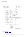
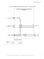
5.3 Three Wire Schematics.............................................................................................................................. 74
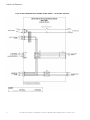
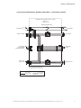
5.4 Four Wire Schematics ............................................................................................................................... 77
66 SSIIAACC--BB OOppeerraattiinngg IInnssttrruuccttiioonnss............................................................................................................................................................................................................................................ 8811
6.1 Sidecar Integrated Accessory Cabinet-Bypass ................................................................................................ 81
6.1.1 Circuit Breakers.................................................................................................................................. 81
6.1.2 Using the UPS when an SIAC-B is Installed .............................................................................................. 81
6.1.3 Transferring the UPS to Maintenance Bypass using an SIAC-B ..................................................................... 84
6.1.4 Transferring the UPS from Maintenance Bypass using an SIAC-B.................................................................. 84
77 MMaaiinntteennaannccee.............................................................................................................................................................................................................................................................................................. 8877
7.1 Important Safety Instructions ...................................................................................................................... 87
7.2 Performing Preventive Maintenance ............................................................................................................. 87
7.2.1 DAILY Maintenance ............................................................................................................................ 87
7.2.2 PERIODIC Maintenance ....................................................................................................................... 87
7.2.3 ANNUAL Maintenance......................................................................................................................... 87
7.3 Maintenance Training ................................................................................................................................ 88
88 PPrroodduucctt SSppeecciiffiiccaattiioonnss ................................................................................................................................................................................................................................................................ 8899
8.1 Model Numbers ....................................................................................................................................... 89
8.2 Specifications .......................................................................................................................................... 89
8.2.1 Input ................................................................................................................................................ 89
8.2.2 Output.............................................................................................................................................. 89
8.2.3 Environmental and Safety Specifications.................................................................................................. 90
99 WWaarrrraannttyy ........................................................................................................................................................................................................................................................................................................ 9911
9.1 Limited Factory Warranty for Three-Phase Eaton 93PM UPS and 93PM UPS Accessory Products.............................. 91
Table of Contents

Eaton 93PM Sidecar Integrated Accessory Cabinet-Bypass (150 kW and 200 kW SIAC-B) Installation and Operation Manual P-164000387—Rev 08 v
LLiisstt ooff FFiigguurreess
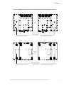
Figure 1. Eaton 93PM SIAC-B (Three or Four Wire) ............................................................................................ 2
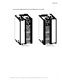
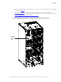
Figure 2. Eaton 93PM 150 Capacity UPS with SIAC-B (Three or Four Wire) ............................................................. 3
Figure 3. Eaton 93PM 200 kW UPS with SIAC-B (Three or Four Wire) .................................................................... 4
Figure 4. Eaton 93PM 150 kW Capacity UPS with SIAC-B (Three or Four Wire) Dimensions (Front View)..................... 12
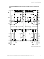
Figure 5. Eaton 93PM 150 kW Capacity UPS with SIAC-B (Three or Four Wire) Dimensions (Top and Bottom
Views) ....................................................................................................................................... 13
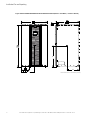
Figure 6. Eaton 93PM 150 kW Capacity UPS with Left-Mounted SIAC-B (Three or Four Wire) –
Center of Gravity.......................................................................................................................... 14
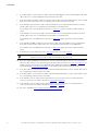
Figure 7. Eaton 93PM 200 kW UPS with SIAC-B (Three or Four Wire) Dimensions (Front View)................................. 16
Figure 8. Eaton 93PM 200 kW UPS with SIAC-B (Three or Four Wire) Dimensions (Top and Bottom Views)................. 17
Figure 9. Eaton 93PM 200 kW UPS with Left-Mounted SIAC-B (Three or Four Wire) – Center of Gravity...................... 18
Figure 10. Eaton 93PM 200 kW UPS with Right-Mounted SIAC-B (Three or Four Wire) – Center of Gravity.................... 19
Figure 11. Eaton 93PM 150 kW Capacity UPS Cabinet with SIAC-B Floor Mounting Bracket Dimensions — Rear
View.......................................................................................................................................... 21
Figure 12. Eaton 93PM 150 kW Capacity UPS Cabinet with SIAC-B Floor Mounting Bracket Dimensions — Top
View.......................................................................................................................................... 22
Figure 13. Eaton 93PM 200 kW UPS Cabinet with SIAC-B Floor Mounting Bracket Dimensions — Rear View ................ 23
Figure 14. Eaton 93PM 200 kW Capacity UPS Cabinet with SIAC-B Floor Mounting Bracket Dimensions — Top
View.......................................................................................................................................... 24
Figure 15. Eaton 93PM 150 kW UPS with SIAC-B (Three or Four Wire) as Shipped on Pallet....................................... 32
Figure 16. Eaton 93PM 200 kW UPS with SIAC-B (Three or Four Wire) as Shipped on Pallet....................................... 33
Figure 17. Eaton 93PM Field Installed SIAC-B as Shipped on Pallet ....................................................................... 34
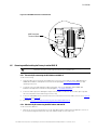
Figure 18. Removing the Pallet Skids and Supports – Eaton 93PM Field Installed SIAC-B........................................... 36
Figure 19. Cabinet Attaching Brackets ............................................................................................................ 39
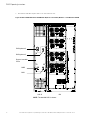
Figure 20. Left-Mounted SIAC-B – RIB, BIB, and MIS Breaker Terminal Locations.................................................... 41
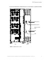
Figure 21. Right-Mounted SIAC-B – RIB, BIB, and MIS Breaker Terminal Locations .................................................. 42
Figure 22. 93PM SIAC-B MIS Input Terminal Detail............................................................................................ 43
Figure 23. 93PM SIAC-B BIB Output Terminal Detail.......................................................................................... 43
Figure 24. 93PM SIAC-B RIB Output Terminal Detail.......................................................................................... 44
Figure 25. 93PM 150 kW Three-Wire and Four-Wire SIAC-B Interface Terminal Location ........................................... 45
Figure 26. 93PM 200 kW Three-Wire and Four-Wire SIAC-B Interface Terminal Location ........................................... 46
Figure 27. SIAC-B Interface Terminal Detail...................................................................................................... 47
Figure 28. 93PM 150 kW Three-Wire and Four-Wire SIAC-B UPS MBP Interface Terminal Location ............................. 49
Figure 29. 93PM 200 kW Three-Wire and Four-Wire SIAC-B UPS MBP Interface Terminal Location ............................. 50
Figure 30. UPS MBP Interface Terminal Detail.................................................................................................. 51
Figure 31. Typical Bus Bar Barrel Lug Mounting – Hardware Assembly Sequence .................................................... 54
Figure 32. 93PM 150 kW Three-Wire and Four-Wire SIAC-B Conduit Landing Wire Entry Locations ............................. 56
Figure 33. 93PM 200 kW Three-Wire and Four-Wire SIAC-B Conduit Landing Wire Entry Locations ............................. 57
Figure 34. 93PM 150 kW Three-Wire and Four-Wire SIAC-B Left-Mounted Bypass — Terminal Locations..................... 58
Figure 35. 93PM 150 kW Three-Wire and Four-Wire SIAC-B Right-Mounted Bypass — Terminal Locations ................... 59
Figure 36. 93PM 200 kW Three-Wire and Four-Wire SIAC-B Left-Mounted Bypass — Terminal Locations..................... 60

vi Eaton 93PM Sidecar Integrated Accessory Cabinet-Bypass (150 kW and 200 kW SIAC-B) Installation and Operation Manual P-164000387—Rev 08
Figure 37. 93PM 200 kW Three-Wire and Four-Wire SIAC-B Right-Mounted Bypass — Terminal Locations ................... 61
Figure 38. 93PM SIAC-B RIB Terminal Detail.................................................................................................... 62
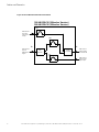
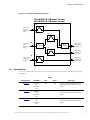
Figure 39. Two-Breaker SIAC-B Internal Oneline ............................................................................................... 65
Figure 40. Three-Breaker SIAC-B Internal Oneline ............................................................................................. 66
Figure 41. Four-Breaker SIAC-B Internal Oneline ............................................................................................... 67
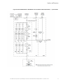
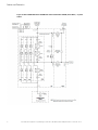
Figure 42. Eaton 93PM 150 kW or 200 kW UPS with Two-Breaker SIAC-B (Three-Wire) — System Online .................... 69
Figure 43. Eaton 93PM 150 kW or 200 kW UPS with Three-Breaker SIAC-B (Three-Wire) — System Online ................. 70
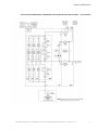
Figure 44. Eaton 93PM 150 kW or 200 kW UPS with Four-Breaker SIAC–B (Three-Wire) — System Online ................... 71
Figure 45. Eaton 93PM 150 kW or 200 kW UPS with Two-Breaker SIAC-B (Four-Wire) — System Online...................... 72
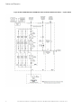
Figure 46. Eaton 93PM 150 kW or 200 kW UPS with Three-Breaker SIAC-B (Four-Wire) — System Online ................... 73
Figure 47. Eaton 93PM 150 kW or 200 kW UPS with Four-Breaker SIAC-B (Four-Wire) — System Online ..................... 74
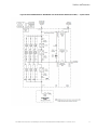
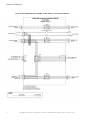
Figure 48. Eaton 93PM 150 kW or 200 kW Three-Wire SIAC-B — Two-Breaker Schematic ........................................ 75
Figure 49. Eaton 93PM 150 kW or 200 kW Three-Wire SIAC-B — Three-Breaker Schematic....................................... 76
Figure 50. Eaton 93PM 150 kW or 200 kW Three-Wire SIAC-B — Four-Breaker Schematic ........................................ 77
Figure 51. Eaton 93PM 150 kW or 200 kW Four-Wire SIAC-B — Two-Breaker Schematic .......................................... 78
Figure 52. Eaton 93PM 150 kW or 200 kW Four-Wire SIAC-B — Three-Breaker Schematic ........................................ 79
Figure 53. Eaton 93PM 150 kW or 200 kW Four-Wire SIAC-B — Four-Breaker Schematic.......................................... 80
Figure 54. Eaton 93PM 150 kW or 200 kW SIAC-B (Three or Four Wire) Breakers – Left-Mounted SIAC-B..................... 82
Figure 55. Eaton 93PM 150 kW or 200 kW SIAC-B (Three or Four Wire) Breakers – Right-Mounted SIAC-B ................... 83
List of Figures

Eaton 93PM Sidecar Integrated Accessory Cabinet-Bypass (150 kW and 200 kW SIAC-B) Installation and Operation Manual P-164000387—Rev 08 vii
LLiisstt ooff TTaabblleess
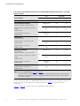
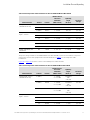
Table 1. SIAC-B Cabinet Weights ................................................................................................................. 10
Table 2. External Power Wiring Recommendations: Eaton 93PM 150 kW and 200 kW Three-Wire SIAC-B – Two and
Three Breaker Maintenance Bypass .................................................................................................. 25
Table 3. External Power Wiring Recommendations: Eaton 93PM 150 kW and 200 kW Three-Wire SIAC-B –
Four Breaker Maintenance Bypass .................................................................................................... 26
Table 4. External Power Wiring Recommendations: Eaton 93PM 150 kW and 200 kW Four-Wire SIAC-B – Two and
Three Breaker Maintenance Bypass .................................................................................................. 27
Table 5. External Power Wiring Recommendations: Eaton 93PM 150 kW and 200 kW Four-Wire SIAC-B –
Four Breaker Maintenance Bypass ................................................................................................... 28
Table 6. External Input Power Cable Terminations for the Eaton 93PM 150 kW Three-Wire SIAC-B ............................ 29
Table 7. External Input Power Cable Terminations for the Eaton 93PM 150 kW Four-Wire SIAC-B.............................. 29
Table 8. External Input Power Cable Terminations for the Eaton 93PM 200 kW Three-Wire SIAC-B ............................ 30
Table 9. External Input Power Cable Terminations for the Eaton 93PM 200 kW Four-Wire SIAC-B.............................. 31
Table 10. SIAC-B Interface Wiring Terminal Block Terminations............................................................................ 47
Table 11. SIAC-B MBP Interface Terminals ...................................................................................................... 48


Eaton 93PM Sidecar Integrated Accessory Cabinet-Bypass (150 kW and 200 kW SIAC-B) Installation and Operation Manual P-164000387—Rev 08 1
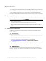
CChhaapptteerr 11 IInnttrroodduuccttiioonn
The Eaton
®
93PM 150 kW and 200 kW Three-Wire Sidecar Integrated Accessory Cabinet-Bypass (SIAC-B) is
designed for use with the 93PM 150 kW and 200 kW Three-Wire UPS systems. The 93PM 150 kW and 200
kW Four-Wire SIAC-B is designed for used with the 93PM 150 kW and 200 kW Four-Wire UPS systems. The
SIAC-B provides maintenance bypass functions with configurable features, enabling adaptation and expansion
without costly electrical rework.
NOTE Startup and operational checks must be performed by an authorized Eaton Customer
Service Engineer, or the warranty terms specified in Chapter 9 Warranty become void.
This service is offered as part of the sales contract for the UPS. Contact an Eaton service
representative in advance (a minimum two-week notice is required) to reserve a
preferred startup date.
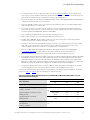
11..11 FFeeaattuurreess
The following descriptions provide a brief overview of the SIAC-B functions:
• Two breaker configuration: The bypass sidecar contains only a Maintenance Bypass (MBP) and
Maintenance Isolation (MIS) breaker. This allows Maintenance bypass for system repair or maintenance.
The critical load is NOT protected in the Maintenance bypass mode.
• Three breaker configuration (used with single-feed systems): Maintenance Bypass (MBP) and
Maintenance Isolation (MIS) breakers, and a Bypass Input Breaker (BIB) enable power to completely
bypass the UPS. The UPS can then be safely serviced or replaced without interrupting power to critical
systems.
• Four breaker configuration (used with dual-feed systems): Maintenance Bypass (MBP) and Maintenance
Isolation (MIS) breakers, and a Bypass Input Breaker (BIB) enable power to completely bypass the UPS. A
Rectifier Input Breaker (RIB) provides a convenient method for removing power from the UPS when using
the maintenance bypass to supply the load. The UPS can then be safely serviced or replaced without
interrupting power to critical systems.
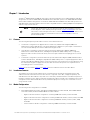
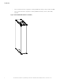
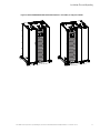
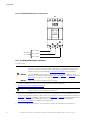
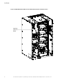
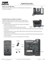
Figure 1 shows the SIAC-B. Figure 2 and Figure 3 show the SIAC-B mounted to the UPS cabinet.
11..22 IInnssttaallllaattiioonn FFeeaattuurreess
The SIAC-B is housed in a single cabinet factory or field attached to and directly integrated with the UPS
cabinet and can be ordered mounted on either the left or right side of the UPS, or shipped separately. The
SIAC-B matches the UPS cabinet in style and color. It has safety shields behind the removable front panel for
hazardous voltage protection and 2-hole bus bar lug input and output terminals reduce installation time. Power
wiring between the UPS and SIAC-B are factory installed. Output power wiring to the critical load is routed
using external conduit.
11..33 MMooddeell CCoonnffiigguurraattiioonnss
The following model configurations are available:
• Eaton 93PM 150 kW Three-Wire SIAC-B, Eaton 93PM 150 kW Four-Wire SIAC-B, Eaton 93PM 200 kW
Three-Wire SIAC-B, and Eaton 93PM 200 kW Four-Wire SIAC-B
– Right-mounted two breaker configuration containing a MBP with auxiliary contacts and MIS
– Right-mounted three breaker configuration containing a MBP with auxiliary contacts, a MIS, and a BIB
– Right-mounted four breaker configuration containing a MBP with auxiliary contacts, a MIS, a BIB,
and a RIB
– Left-mounted two breaker configuration containing a MBP with auxiliary contacts and MIS

2 Eaton 93PM Sidecar Integrated Accessory Cabinet-Bypass (150 kW and 200 kW SIAC-B) Installation and Operation Manual P-164000387—Rev 08
– Left-mounted three breaker configuration containing a MBP with auxiliary contacts, a MIS, and a BIB
– Left-mounted four breaker configuration containing a MBP with auxiliary contacts, a MIS, a BIB,
and a RIB
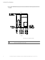
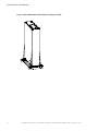
Figure 1. Eaton 93PM SIAC-B (Three or Four Wire)
Introduction


4 Eaton 93PM Sidecar Integrated Accessory Cabinet-Bypass (150 kW and 200 kW SIAC-B) Installation and Operation Manual P-164000387—Rev 08
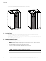
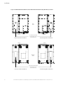
Figure 3. Eaton 93PM 200 kW UPS with SIAC-B (Three or Four Wire)
200 kW UPS with 200 kW UPS with
Left-Mounted Sidecar Right-Mounted Sidecar
11..44 UUssiinngg TThhiiss MMaannuuaall
This manual describes how to install the SIAC-B and is divided into chapters. Read and understand the
procedures described to ensure trouble-free installation and operation.
Read through each procedure before beginning the procedure. Perform only those procedures that apply to the
UPS system being installed or operated.
11..55 CCoonnvveennttiioonnss UUsseedd iinn TThhiiss MMaannuuaall
This manual uses these type conventions:
• Bold type highlights important concepts in discussions, key terms in procedures, and menu options, or
represents a command or option that you type or enter at a prompt.
• Italic type highlights notes and new terms where they are defined.
• Screen type represents information that appears on the screen or LCD.
Icon
Description
Note Information notes call attention to important features or instructions.
[Keys] Brackets are used when referring to a specific key, such as [Enter] or [Ctrl].
Introduction

Eaton 93PM Sidecar Integrated Accessory Cabinet-Bypass (150 kW and 200 kW SIAC-B) Installation and Operation Manual P-164000387—Rev 08 5
In this manual, the term UPS refers only to the UPS cabinet and its internal elements. The term UPS
system refers to the entire power protection system – the UPS cabinet, an external battery system, and
options or accessories installed.
The term line-up-and-match refers to accessory cabinets that are physically located adjacent to the UPS.
The term standalone refers to accessory cabinets that are located separate from the UPS.
11..66 SSyymmbboollss,, CCoonnttrroollss,, aanndd IInnddiiccaattoorrss
The following are examples of symbols used on the UPS or accessories to alert you to important information:
Special Symbols
The following are examples of symbols used on the UPS or accessories to alert you to important
information:
RISK OF ELECTRIC SHOCK - Observe the warning associated with the risk of
electric shock symbol.
CAUTION: REFER TO OPERATOR'S MANUAL - Refer to your operator's manual for
additional information, such as important operating and maintenance
instructions.
This symbol indicates that you should not discard the UPS or the UPS batteries
in the trash. This product contains sealed, lead‐acid batteries and must be
disposed of properly. For more information, contact your local recycling/reuse or
hazardous waste center.
This symbol indicates that you should not discard waste electrical or electronic
equipment (WEEE) in the trash. For proper disposal, contact your local
recycling/reuse or hazardous waste center.
Eaton, Powerware, and BladeUPS are registered trademarks of Eaton Corporation or its subsidiaries and affiliates.
Phillips and Pozidriv are registered trademarks of Phillips Screw Company.
ECopyright 2008–2010 Eaton Corporation, Raleigh, NC, USA. All rights reserved. No part of this document may be
reproduced in any way without the express written approval of Eaton Corporation.
RISK OF ELECTRIC SHOCK - Observe the warning associated with the risk of electric shock symbol.
Special Symbols
The following are examples of symbols used on the UPS or accessories to alert you to important
information:
RISK OF ELECTRIC SHOCK - Observe the warning associated with the risk of
electric shock symbol.
CAUTION: REFER TO OPERATOR'S MANUAL - Refer to your operator's manual for
additional information, such as important operating and maintenance
instructions.
This symbol indicates that you should not discard the UPS or the UPS batteries
in the trash. This product contains sealed, lead‐acid batteries and must be
disposed of properly. For more information, contact your local recycling/reuse or
hazardous waste center.
This symbol indicates that you should not discard waste electrical or electronic
equipment (WEEE) in the trash. For proper disposal, contact your local
recycling/reuse or hazardous waste center.
Eaton, Powerware, and BladeUPS are registered trademarks of Eaton Corporation or its subsidiaries and affiliates.
Phillips and Pozidriv are registered trademarks of Phillips Screw Company.
ECopyright 2008–2010 Eaton Corporation, Raleigh, NC, USA. All rights reserved. No part of this document may be
reproduced in any way without the express written approval of Eaton Corporation.
CAUTION: REFER TO OPERATOR'S MANUAL - Refer to your operator's manual for additional
information, such as important operating and maintenance instructions.
Special Symbols
The following are examples of symbols used on the UPS or accessories to alert you to important
information:
RISK OF ELECTRIC SHOCK - Observe the warning associated with the risk of
electric shock symbol.
CAUTION: REFER TO OPERATOR'S MANUAL - Refer to your operator's manual for
additional information, such as important operating and maintenance
instructions.
This symbol indicates that you should not discard the UPS or the UPS batteries
in the trash. This product contains sealed, lead‐acid batteries and must be
disposed of properly. For more information, contact your local recycling/reuse or
hazardous waste center.
This symbol indicates that you should not discard waste electrical or electronic
equipment (WEEE) in the trash. For proper disposal, contact your local
recycling/reuse or hazardous waste center.
Eaton, Powerware, and BladeUPS are registered trademarks of Eaton Corporation or its subsidiaries and affiliates.
Phillips and Pozidriv are registered trademarks of Phillips Screw Company.
ECopyright 2008–2010 Eaton Corporation, Raleigh, NC, USA. All rights reserved. No part of this document may be
reproduced in any way without the express written approval of Eaton Corporation.
This symbol indicates that you should not discard the UPS or the UPS batteries in the trash. This
product contains sealed, lead-acid batteries and must be disposed of properly. For more information,
contact your local recycling/reuse or hazardous waste center.
Special Symbols
The following are examples of symbols used on the UPS or accessories to alert you to important
information:
RISK OF ELECTRIC SHOCK - Observe the warning associated with the risk of
electric shock symbol.
CAUTION: REFER TO OPERATOR'S MANUAL - Refer to your operator's manual for
additional information, such as important operating and maintenance
instructions.
This symbol indicates that you should not discard the UPS or the UPS batteries
in the trash. This product contains sealed, lead‐acid batteries and must be
disposed of properly. For more information, contact your local recycling/reuse or
hazardous waste center.
This symbol indicates that you should not discard waste electrical or electronic
equipment (WEEE) in the trash. For proper disposal, contact your local
recycling/reuse or hazardous waste center.
Eaton, Powerware, and BladeUPS are registered trademarks of Eaton Corporation or its subsidiaries and affiliates.
Phillips and Pozidriv are registered trademarks of Phillips Screw Company.
ECopyright 2008–2010 Eaton Corporation, Raleigh, NC, USA. All rights reserved. No part of this document may be
reproduced in any way without the express written approval of Eaton Corporation.
This symbol indicates that you should not discard waste electrical or electronic equipment (WEEE) in
the trash. For proper disposal, contact your local recycling/reuse or hazardous waste center.
11..77 FFoorr MMoorree IInnffoorrmmaattiioonn
Refer to the Eaton 93PM UPS (20–150 kW, 480V – 150 kW Capacity Frame) Installation and Operation
Manual, the Eaton 93PM UPS (20–150 kW, 480V Four Wire – 150 kW Capacity Frame) Installation and
Operation Manual, the Eaton 93PM Emergency Lighting UPS (20–40 kW, 480V Four Wire UL 924)
Installation and Operation Manual, the Eaton 93PM UPS (20–200 kW, 480V – 200 kW Frame) Installation
and Operation Manual, or the Eaton 93PM UPS (20–200 kW, 480V Four Wire –200 kW Frame) Installation
and Operation Manual for the following additional information:
• UPS, optional components, and accessory installation instructions, including site preparation, planning for
installation, and wiring and safety information. Detailed illustrations of cabinets and optional accessories
with dimensional and connection point drawings are provided.
• UPS operation, including UPS controls, functions of the UPS, standard features and optional accessories,
procedures for starting and stopping the UPS, and information about maintenance and responding to
system events.
• Communication capabilities of the UPS system.
Refer to the Eaton 93PM Integrated Accessory Cabinet-Distribution (50 kW, 100 kW, 150 kW, and 200 kW
IAC-D) Installation and Operation Manual for the following additional information:
• Installation instructions, including site preparation, planning for installation, wiring and safety information,
and detailed illustrations of cabinets with dimensional and connection point drawings
Introduction

6 Eaton 93PM Sidecar Integrated Accessory Cabinet-Bypass (150 kW and 200 kW SIAC-B) Installation and Operation Manual P-164000387—Rev 08
• Operation, including breakers, standard features and optional accessories, procedures for using the tie and
bypass functions, and information about maintenance
Visit www.eaton.com/powerquality or contact an Eaton service representative for information on how to obtain
copies of these manuals.
11..88 GGeettttiinngg HHeellpp
If help is needed with any of the following:
Scheduling initial startup
Regional locations and telephone numbers
A technical question about any of the information in this manual
A question this manual does not answer
Please call the Customer Reliability Center at:
United States:
1-800-843-9433
Canada:
1-800-461-9166 ext 260
All other countries: Call your local service representative
Please use the following e-mail address for manual comments, suggestions, or to report an error in this
manual:
11..99 EEqquuiippmmeenntt RReeggiissttrraattiioonn
Please visit www.eaton.com/pq/register to register your new Eaton UPS / Eaton UPS Accessory.
Model Number:
Serial Number:
Introduction

Eaton 93PM Sidecar Integrated Accessory Cabinet-Bypass (150 kW and 200 kW SIAC-B) Installation and Operation Manual P-164000387—Rev 08 7
CChhaapptteerr 22 SSaaffeettyy WWaarrnniinnggss
IMPORTANT SAFETY INSTRUCTIONS SAVE THESE INSTRUCTIONS
This manual contains important instructions that should be followed during installation and maintenance of the
UPS system and batteries. Read all instructions before operating the equipment and save this manual for future
reference.
The UPS system is designed for industrial or computer room applications, and contains safety shields behind
the door and front panels. However, the UPS system is a sophisticated power system and should be handled
with appropriate care.
DANGER
This UPS system contains LETHAL VOLTAGES. All repairs and service should be performed by AUTHORIZED
SERVICE PERSONNEL ONLY. There are NO USER SERVICEABLE PARTS inside the UPS.
WARNING
• The UPS system is powered by its own energy source (batteries). The output terminals may carry live
voltage even when the UPS is disconnected from an AC source.
• To reduce the risk of fire or electric shock, install this UPS system in a temperature and humidity
controlled, indoor environment, free of conductive contaminants. Ambient temperature must not exceed
40°C (104°F). Do not operate near water or excessive humidity (95% maximum). The system is not
intended for outdoor use.
• As a result of the connected loads high leakage current is possible. Connection to earth ground is required
for safety and proper product operation. Do not check UPS system operation by any action that includes
removal of the earth (ground) connection with loads attached.
• Ensure all power is disconnected before performing installation or service.
• ELECTRIC ENERGY HAZARD. Do not attempt to alter any UPS system or battery wiring or connectors.
Attempting to alter wiring can cause injury.
CAUTION
• Installation or servicing should be performed by qualified service personnel knowledgeable of UPS and
battery systems, and required precautions. Keep unauthorized personnel away from equipment. Consider
all warnings, cautions, and notes before installing or servicing equipment.
• Keep the Accessory cabinet doors closed and front panels installed to ensure proper cooling airflow and to
protect personnel from dangerous voltages inside the unit.
• Do not install or operate the UPS system close to gas or electric heat sources.
• The operating environment should be maintained within the parameters stated in this manual.
• Keep surroundings uncluttered, clean, and free from excess moisture.
• Observe all DANGER, CAUTION, and WARNING notices affixed to the inside and outside of the
equipment.


Eaton 93PM Sidecar Integrated Accessory Cabinet-Bypass (150 kW and 200 kW SIAC-B) Installation and Operation Manual P-164000387—Rev 08 9
CChhaapptteerr 33 IInnssttaallllaattiioonn PPllaann aanndd UUnnppaacckkiinngg
This chapter includes planning for the Eaton 93PM 150 kW and 200 kW Sidecar Integrated Accessory Cabinet-
Bypass (SIAC-B).
NOTE The SIAC-B is typically attached to and directly integrated with the UPS cabinet at the
factory but it can be ordered and shipped separately from the UPS and installed onsite.
This section must be used along with the applicable Eaton 93PM UPS Installation and
Operation manual, listed in paragraph 1.7 For More Information, during installation
planning and unpacking.
33..11 UUssee tthhee ffoolllloowwiinngg bbaassiicc sseeqquueennccee ooff sstteeppss ttoo iinnssttaallll tthhee SSIIAACC--BB::
1. Create an installation plan for the SIAC-B.
2. Prepare your site for the SIAC-B.
3. Inspect and unpack the SIAC-B.
4. Unload and install the SIAC-B.
5. Externally wire the SIAC-B.
6. Complete the Installation Checklist.
7. Have authorized service personnel perform preliminary operational checks and start up the system.
NOTE Startup and operational checks must be performed by an authorized Eaton Customer
Service Engineer, or the warranty terms specified in Chapter 9 Warranty become void.
This service is offered as part of the sales contract for the UPS. Contact an Eaton service
representative in advance (usually a two-week notice is required) to reserve a preferred
startup date.
33..22 CCrreeaattiinngg aann IInnssttaallllaattiioonn PPllaann
Before installing the SIAC-B, read and understand how this manual applies to the system being installed. Use
the procedures and illustrations in this section to create a logical plan for installing the SIAC-B.
33..33 PPrreeppaarriinngg tthhee SSiittee
For the UPS system to operate at peak efficiency, the installation site should meet the environmental
parameters outlined in this manual. The operating environment must meet the weight, clearance, and
environmental requirements specified for the applicable accessory cabinet. Specifications subject to change.
33..33..11 EEnnvviirroonnmmeennttaall aanndd IInnssttaallllaattiioonn CCoonnssiiddeerraattiioonnss
The UPS system installation, including the SIAC-B, must meet the following guidelines:
• The system must be installed on a level floor suitable for computer or electronic equipment.
• The system must be operated at an altitude no higher than 1500m (5000 ft) without derating. For additional
assistance with high altitude operation, contact an Eaton service representative (see paragraph
1.8 Getting Help).
• The system must be installed in a temperature and humidity controlled indoor area free of conductive
contaminants.
Failure to follow guidelines may void your warranty.
The basic environmental requirements for operation of the SIAC-B are:

10 Eaton 93PM Sidecar Integrated Accessory Cabinet-Bypass (150 kW and 200 kW SIAC-B) Installation and Operation Manual P-164000387—Rev 08
• Ambient Temperature Range: 5–40°C (41–104°F)
• Recommended Operating Range: 5–40°C (41–104°F)
• Maximum Relative Humidity: 5–95%, noncondensing
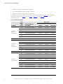
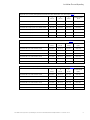
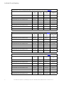
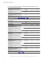
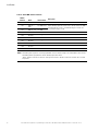
The SIAC-B operating environment must meet the weight requirements shown in Table 1. The SIAC-B size
requirements are shown in Figure 4 through Figure 6 or Figure 7 through Figure 9. Dimensions are in
millimeters (inches).
Table 1. SIAC-B Cabinet Weights
UPS Model
Power
Rating –
UPM
Quantity
Left or Right-Mounted
SIAC-B Model
Weight kg (lb)
Shipping
Installed
Point Loading
Eaton 93PM
Capacity
Three-Wire UPS
150-1
Three-Wire SIAC-B (2-Breaker) 572 (1259) 541 (1192) 8 at 68 (149)
150-2
Three-Wire SIAC-B (2-Breaker) 635 (1399) 604 (1332) 8 at 76 (167)
150-3
Three-Wire SIAC-B (2-Breaker) 699 (1540) 668 (1473) 8 at 84 (184)
150-1
Three-Wire SIAC-B (4-Breaker) 585 (1289) 554 (1222) 8 at 69 (153)
150-2
Three-Wire SIAC-B (4-Breaker) 649 (1430) 618 (1363) 8 at 77 (170)
150-3
Three-Wire SIAC-B (4-Breaker) 713 (1570) 682 (1503) 8 at 85 (188)
Eaton 93PM
Capacity
Four-Wire UPS
150-1
Four-Wire SIAC-B (2-Breaker) 600 (1322) 569 (1255) 8 at 71(157)
150-2
Four-Wire SIAC-B (2-Breaker) 664 (1462) 633 (1395) 8 at 79 (174)
150-3
Four-Wire SIAC-B (2-Breaker) 727 (1603) 696 (1536) 8 at 87 (192)
150-1
Four-Wire SIAC-B (4-Breaker) 614 (1352) 583 (1285) 8 at 73 (161)
150-2
Four-Wire SIAC-B (4-Breaker) 677 (1492) 646 (1425) 8 at 81 (178)
150-3
Four-Wire SIAC-B (4-Breaker) 741 (1633) 710 (1566) 8 at 89 (196)
Eaton 93PM
Three-Wire UPS
200-1
Three-Wire SIAC-B (2-Breaker) 624 (1374) 593 (1307) 8 at 74 (163)
200-2
Three-Wire SIAC-B (2-Breaker) 687 (1514) 656 (1447) 8 at 82 (181)
200-3
Three-Wire SIAC-B (2-Breaker) 751 (1655) 720 (1588) 8 at 90 (199)
200-4
Three-Wire SIAC-B (2-Breaker) 815 (1795) 784 (1728) 8 at 98 (216)
200-1
Three-Wire SIAC-B (4-Breaker) 637 (1404) 606 (1337) 8 at 76 (167)
200-2
Three-Wire SIAC-B (4-Breaker) 701 (1544) 670 (1477) 8 at 84 (185)
200-3
Three-Wire SIAC-B (4-Breaker) 765 (1685) 734 (1618) 8 at 92 (202)
200-4
Three-Wire SIAC-B (4-Breaker) 828 (1825) 797 (1758) 8 at 100 (220)
Installation Plan and Unpacking

Eaton 93PM Sidecar Integrated Accessory Cabinet-Bypass (150 kW and 200 kW SIAC-B) Installation and Operation Manual P-164000387—Rev 08 11
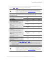
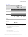
Table 1. SIAC-B Cabinet Weights (Continued)
UPS Model
Power
Rating –
UPM
Quantity
Left or Right-Mounted
SIAC-B Model
Weight kg (lb)
Shipping
Installed
Point Loading
Eaton 93PM
Four-Wire UPS
200-1
Four-Wire SIAC-B (2-Breaker) 658 (1449) 627 (1382) 8 at 78 (173)
200-2
Four-Wire SIAC-B (2-Breaker) 721 (1589) 690 (1522) 8 at 86 (190)
200-3
Four-Wire SIAC-B (2-Breaker) 785 (1730) 754 (1663) 8 at 94 (208)
200-4
Four-Wire SIAC-B (2-Breaker) 849 (1875) 818 (1808) 8 at 102 (288)
200-1
Four-Wire SIAC-B (4-Breaker) 871 (1479) 640 (1412) 8 at 80 (226)
200-2
Four-Wire SIAC-B (4-Breaker) 735 (1619) 704 (1552) 8 at 88 (194)
200-3
Four-Wire SIAC-B (4-Breaker) 799 (1760) 768 (1693) 8 at 96 (212)
200-4
Four-Wire SIAC-B (4-Breaker) 862 (1900) 831 (1833) 8 at 104 (229)
The clearances required around the SIAC-B are the same as the attached UPS.
Installation Plan and Unpacking

12 Eaton 93PM Sidecar Integrated Accessory Cabinet-Bypass (150 kW and 200 kW SIAC-B) Installation and Operation Manual P-164000387—Rev 08
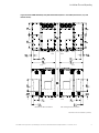
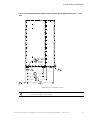
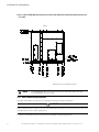
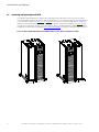
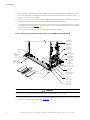
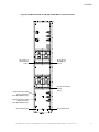
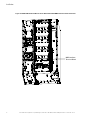
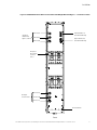
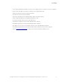
Figure 4. Eaton 93PM 150 kW Capacity UPS with SIAC-B (Three or Four Wire) Dimensions (Front View)
Dimensions are in millimeters [inches]
UPS with Left-Mounted SIAC-B UPS with Right-Mounted SIAC-B
Installation Plan and Unpacking
Page is loading ...
Page is loading ...
Page is loading ...
Page is loading ...
Page is loading ...
Page is loading ...
Page is loading ...
Page is loading ...
Page is loading ...
Page is loading ...
Page is loading ...
Page is loading ...
Page is loading ...
Page is loading ...
Page is loading ...
Page is loading ...
Page is loading ...
Page is loading ...
Page is loading ...
Page is loading ...
Page is loading ...
Page is loading ...
Page is loading ...
Page is loading ...
Page is loading ...
Page is loading ...
Page is loading ...
Page is loading ...
Page is loading ...
Page is loading ...
Page is loading ...
Page is loading ...
Page is loading ...
Page is loading ...
Page is loading ...
Page is loading ...
Page is loading ...
Page is loading ...
Page is loading ...
Page is loading ...
Page is loading ...
Page is loading ...
Page is loading ...
Page is loading ...
Page is loading ...
Page is loading ...
Page is loading ...
Page is loading ...
Page is loading ...
Page is loading ...
Page is loading ...
Page is loading ...
Page is loading ...
Page is loading ...
Page is loading ...
Page is loading ...
Page is loading ...
Page is loading ...
Page is loading ...
Page is loading ...
Page is loading ...
Page is loading ...
Page is loading ...
Page is loading ...
Page is loading ...
Page is loading ...
Page is loading ...
Page is loading ...
Page is loading ...
Page is loading ...
Page is loading ...
Page is loading ...
Page is loading ...
Page is loading ...
Page is loading ...
Page is loading ...
Page is loading ...
Page is loading ...
Page is loading ...
Page is loading ...
Page is loading ...
Page is loading ...
-
 1
1
-
 2
2
-
 3
3
-
 4
4
-
 5
5
-
 6
6
-
 7
7
-
 8
8
-
 9
9
-
 10
10
-
 11
11
-
 12
12
-
 13
13
-
 14
14
-
 15
15
-
 16
16
-
 17
17
-
 18
18
-
 19
19
-
 20
20
-
 21
21
-
 22
22
-
 23
23
-
 24
24
-
 25
25
-
 26
26
-
 27
27
-
 28
28
-
 29
29
-
 30
30
-
 31
31
-
 32
32
-
 33
33
-
 34
34
-
 35
35
-
 36
36
-
 37
37
-
 38
38
-
 39
39
-
 40
40
-
 41
41
-
 42
42
-
 43
43
-
 44
44
-
 45
45
-
 46
46
-
 47
47
-
 48
48
-
 49
49
-
 50
50
-
 51
51
-
 52
52
-
 53
53
-
 54
54
-
 55
55
-
 56
56
-
 57
57
-
 58
58
-
 59
59
-
 60
60
-
 61
61
-
 62
62
-
 63
63
-
 64
64
-
 65
65
-
 66
66
-
 67
67
-
 68
68
-
 69
69
-
 70
70
-
 71
71
-
 72
72
-
 73
73
-
 74
74
-
 75
75
-
 76
76
-
 77
77
-
 78
78
-
 79
79
-
 80
80
-
 81
81
-
 82
82
-
 83
83
-
 84
84
-
 85
85
-
 86
86
-
 87
87
-
 88
88
-
 89
89
-
 90
90
-
 91
91
-
 92
92
-
 93
93
-
 94
94
-
 95
95
-
 96
96
-
 97
97
-
 98
98
-
 99
99
-
 100
100
-
 101
101
-
 102
102


Eaton 93PM 200 kW SIAC-B Four-Wire Operating instructions
- Type
- Operating instructions
- This manual is also suitable for
Ask a question and I''ll find the answer in the document
Finding information in a document is now easier with AI
Related papers
-
Eaton 93PM 200 kW SIAC-B Four-Wire Operating instructions
-
-
-
-
-
-
-
-
-
Other documents
-
Avid Technology VENUE D-Show Sidecar User manual
-
Eaton Electrical Powerware BladeUPS Bar User manual
-
NCR 7705 Kit Instructions
-
 POPP Cummunicatios spa 500s User manual
-
CyberPower MBP63A2 User manual
-
 Digital Tigers SideCar MMS Series User manual
-
Commodore A1060 Sidecar User manual
-
APC Smart-UPS VT Installation guide
-
Powerware UPS Sidecar 9390 User manual
-
Alpha Sidecar PDF Installation guide

