APC Smart-UPS VT Installation guide
- Type
- Installation guide
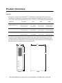
APC Smart-UPS VT is a reliable power protection solution for critical equipment in data centers, server rooms, and other demanding environments. It offers scalable runtime with the addition of external battery packs, intelligent battery management for optimized performance, and pure sine wave output for compatibility with sensitive electronics. With its user-replaceable batteries and modular design, the Smart-UPS VT is easy to maintain and service. Advanced communications capabilities enable remote monitoring and management, while the intuitive LCD display provides clear status information.
APC Smart-UPS VT is a reliable power protection solution for critical equipment in data centers, server rooms, and other demanding environments. It offers scalable runtime with the addition of external battery packs, intelligent battery management for optimized performance, and pure sine wave output for compatibility with sensitive electronics. With its user-replaceable batteries and modular design, the Smart-UPS VT is easy to maintain and service. Advanced communications capabilities enable remote monitoring and management, while the intuitive LCD display provides clear status information.


-
 1
1
-
 2
2
-
 3
3
-
 4
4
-
 5
5
-
 6
6
-
 7
7
-
 8
8
-
 9
9
-
 10
10
-
 11
11
-
 12
12
-
 13
13
-
 14
14
-
 15
15
-
 16
16
-
 17
17
-
 18
18
-
 19
19
-
 20
20
-
 21
21
-
 22
22
-
 23
23
-
 24
24
-
 25
25
-
 26
26
-
 27
27
-
 28
28
-
 29
29
-
 30
30
-
 31
31
-
 32
32
-
 33
33
-
 34
34
-
 35
35
-
 36
36
-
 37
37
-
 38
38
-
 39
39
-
 40
40
-
 41
41
-
 42
42
-
 43
43
-
 44
44


APC Smart-UPS VT Installation guide
- Type
- Installation guide
APC Smart-UPS VT is a reliable power protection solution for critical equipment in data centers, server rooms, and other demanding environments. It offers scalable runtime with the addition of external battery packs, intelligent battery management for optimized performance, and pure sine wave output for compatibility with sensitive electronics. With its user-replaceable batteries and modular design, the Smart-UPS VT is easy to maintain and service. Advanced communications capabilities enable remote monitoring and management, while the intuitive LCD display provides clear status information.
Ask a question and I''ll find the answer in the document
Finding information in a document is now easier with AI
Related papers
-
APC WONSITENBD-SB-15 Datasheet
-
Schneider Electric Surface Mounting Brackets for NetBotz Room Monitor Appliance/Camera Pod Installation guide
-
Schneider Electric 3500 User manual
-
Schneider Electric SUVTRF30KH User manual
-
-
APC AIS 3000 User manual
-
-
-
-
Other documents
-
American Power Conversion CTEG4-240MB-5 User manual
-
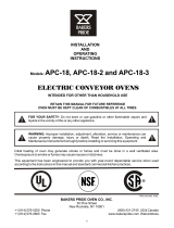 Bakers Pride APC-18-3 Operating instructions
-
Eaton ERA010 Datasheet
-
-
-
Eaton Powerware 9355 Operating instructions
-
Liebert NXC 30kVA User manual
-
-
-
