Page is loading ...

INSTALLATION & OPERATING INSTRUCTIONS
The
Stratford Multifuel
Sf & Si Stoves
Stratford Sf 50 Convector
PLEASE RETAIN THESE INSTRUCTIONS FOR FUTURE REFERENCE

2
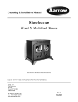
Congratulations on your choice of an Aarrow Stove.
More than 20 years experience has been put into the
development of our Stratford Multifuel to ensure ultimate
performance and years of trouble free enjoyment.
Every detail on the fire has been carefully engineered and
designed which is why we are so confident in the reliability of
our product.
Should you have any questions about our Stratford Stoves that
are not covered in this manual, please contact the Aarrow dealer
in your area, or call our Technical support department on
01308 427234
Flaming Good Fires!
© COPYRIGHT July 2001
Aarrow Fires Ltd
This booklet has copyright & may not be
copied in whole or part or be used for any
purpose other than that for which it is
supplied without express written consent
from Aarrow fires Ltd.

3
The
Stratford Sf & Si
Installation and Operating
Instructions
Contents
Operating Instructions
1 Introduction - The Principle of the Fire 5
2 Checklist 6
A - Stratford Sf
B - Stratford Si
3 Fire Bed 7
4 Firebrick Lining for Sf only 8
5 Throat Inspection 9
6 The Air System 10
A - Interlock
B - Multi-Purpose Operating Tool
7 Glass/Trim 12
8 Door Adjustments 13
9 Spare Parts List 14
A - Stratford Sf
B - Stratford Si
10 Accessories 16
11 Fuels 17
12 Lighting the Fire 18
13 Overnight burning 19
14 Ash removal 20
15 Cleaning 21
16 Safety 22
Installation Instructions
17 General 23
18 Handling 23
19 Hearth 23
20 Combustible Materials 23
21 Air For Combustion 24
22 Builders Opening/Chimney Breast 24
23 Chimney 24
24 Installing the Fire 25
A - Stratford Sf
B - Stratford Si
25 Flues & Chimneys 27
26 Water Connections 30
27 Final Check 31
28 Guarantee 32
29 Customer Registration 32
30 Service Record 33

4
WARNING
To All Solid Fuel Users
PETROLEUM COKE
SOME OF WHOSE BRAND NAMES ARE
"CALCO", "PETROCOKE" OR "WONDERCO"
MUST NOT
BE BURNED IN THIS APPLIANCE
TO USE THIS FUEL WILL INVALIDATE THE APPLIANCE
WARRANTY
IF IN DOUBT CONTACT THE SOLID FUEL ASSOCIATION
TELEPHONE FREEPHONE 0800 600000
THE USE OF SPARE PARTS OTHER THAN THOSE
SUPPLIED BY AARROW FIRES LTD WILL INVALIDATE
THE APPPLIANCE GUARANTEE.

5
Operating Instructions For
The Stratford Multifuel Sf & Si.
1. INTRODUCTION - THE PRINCIPLE OF THE FIRE
Your Aarrow Fire is built to the highest standard of craftsmanship using the best materials and the most modern
equipment available. It is a highly efficient and sophisticated piece of machinery and when properly installed and
operated it should provide a lifetime of heating satisfaction.
Safety is the most important consideration when installing your fire. If not properly installed and operated a
house fire may result. You should check your local Building Regulations and conform to all relevant fire safety
standards.
Aarrow Fires produce a variety of appliances that range from the traditional in appearance to the ultra modern,
all bristling with "High tech" features.
Model types include simple room heaters, convectors, integral boiler models and inset units. Your Aarrow fire is
constructed from twin wall steel strengthened where necessary. Cast iron is used where appropriate for long life.
All fire doors are fitted with special high temperature ceramic glass panels through which the fire can be viewed.
All units are fitted with a cast iron grate to give full multifuel facility and positive de-ashing.
All models except integral boiler models and insets are lined with heat reflective panels which ensure complete
combustion and provide a good heat store to even out fluctuations in burning.
An internal throat plate produces turbulence to encourage secondary combustion and directs the flue gas around
the whole upper firebox before allowing it to escape to the chimney.
The primary air for burning enters the ash pit chamber beneath the grate, controlled by the air inlet mechanism or
by the thermostatically controlled damper where fitted.
The provision of two inlets gives a wide range of primary air/secondary air, under draught/over draught
combinations. The optimum settings will only be established by experience in the firing the appliance, and will
depend on type of fuel, the position of the appliance in the house, condition of chimney etc.
Aarrow fires are also fitted with an "air wash" so called because it provides a curtain of high speed preheated air
in front of the glass to help keep it clean and to provide secondary air/over draught.
Solid Fuel.
To burn solid fuel efficiently the main source of combustion air should be under draught entering the ash pit
chamber. The air wash can be opened a little to allow sufficient air to keep the glass clean and provide secondary
air for afterburn.
Wood
Wood burns very efficiently on a bed of its own ash and an over draught. It will also burn successfully with an
under draught, and on appliances fitted with a thermostat this should be the main source of combustion air in
order for the thermostatic control to be effective.
Mixed Solid Fuel and Wood
When burning mixed fuels the grate should be set to the coal burning position with combustion air entering
equally from above the fire through the air wash, and below through the ash pit door.
Diagrams and notes on the features of the different types of fires are set out in the sections following this one.

6
2. CHECK LIST
Inside the appliance you should find the following.
Stratford Sf
30
Stratford Sf
50
Stratford Sf
70
Stratford Sf
90
Stratford Si
40
Stratford Si
60
Conv. Boil. Conv. Boil. Conv. Boil. Conv. Boil. Conv. Boil. Conv. Boil.
Grate Bars
7 7 9 9 11 11 11 11 7 7 11 11
Fire Bed Surround
7 7 9 11 3 4
Refractory Lining
230x197
4 4 3 5
Refractory lining
230x138
4 2
Refractory lining
230x115
1
Rear Brick Locking
Channel
1 1
Fuel Retainers
3 3 3 3 3 3 3 3 3 3 3 3
Throat Plate
1 1 1 1 1 1 1 1 1 1 1 1
Flue Spigot
1(5'') 1(5'') 1(5'') 1(5'') 1(6'') 1(6'') 1(6'') 1(6'')
Hot Plate
1(5'') 1(5'') 1(5'') 1(5'') 1(6'') 1(6'') 1(6'') 1(6'')
Ash Pan
1 1 1 1 1 1 1 1 1 1 1 1
Operating Tool
1 1 1 1 1 1 1 1 1 1 1 1
Thermostat*
1 1 1 1 1* 1* 1* 1*
Instructions
1 1 1 1 1 1 1 1 1 1 1 1
* Only the knob, the thermostat is already fitted to the stove
The model and Serial No. of your fire can be found stamped into the casing, centrally just below the bottom edge
of the fire door aperture.
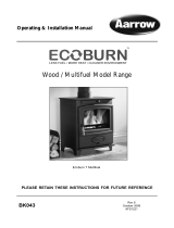
A - Stratford Freestanding - Sf
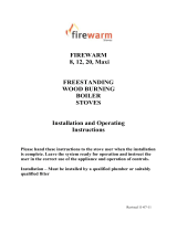
B - Stratford Inset - Si
Flue outlet socket
Air wash control
Fire door
Fuel retainers
Multifuel
Ashpit door
Operating tool
Thermostat
damper plate
Thermostat
control unit
Sensor phial
Multifuel grate
Ashpan
Front trim
Boiler unit
Flow tapping
Return tapping
Grate
Control
Multifuel grate
Ashpan
Ashpit door
Operating tool
Firebrick
Rear flue
Fuel retainers
Fire door
Hot plate
Top flue
Air wash control
WOOD
COAL
MULTIFUEL
GRATE
CONTROL

7
3. FIRE BED
Grate
The grates in the Stratford Sf & Si Multifuel units comprise a series of reciprocating cast iron bars seated on a
pivoted "comb". All bars in the grate are identical, but every other bar is turned through 180 degrees, with the
ends of the bars marked "H" sitting on the high sections of the comb, and the ends marked "L" sitting on the low
sections.
Assembling the Grate (Fig.1)
To assemble the grate, fit bars to low sections of the comb first, inserting end market "H" into rear channel with
groove on underside of bar located on upstand tab, and then lowering end marked "L" onto the low section of the
comb. The upper bar is fitted in a similar manner, but with the end marked "L" inserted in the rear channel, and
the end marked "H" seated on the high section of the comb.
Figure 1
Grate bar Replacement
After extended use it may be necessary to replace some of the grate bars. Periodic inspection of the bars is
recommended and the removal of any nails or wire that may be present after burning wood. All the grate bars in
each appliance are identical and can easily be lifted out after removal of the fuel retainers.
Remove damaged grate bars and replace with casting of the same type, fitting as per instruction above. (Check
Identification letters on the casting when reordering).
Riddle Lever for Sf only
(Fig 2a)
The riddle lever gives effective de-ashing, and also allows the grate to be set in the coal burning or wood burning
position, as indicated on the right hand side of the appliance.
For Si
use the operating tool provided. Rotating the end shaft of the comb with the operating tool gives effective
de-ashing, and also allows the grate to be set in the coal or wood burning position, as indicated on the right hand
side of the appliance (Fig 2b).
Figure 2a Figure 2b
FITTING BARS TO COMB
ASSEMBLED GRATE
COMB
"HIGH" GRATE BAR
"LOW" GRATE BAR
COMB EXTENSION SHAFT
WOOD
COAL
COAL
WOOD
GRATE SETTING
INDICATORS
COMB EXTENSION
OPERATING TOOL

8
4. REFRACTORY LINING FOR Sf CONVECTOR MODELS ONLY
Warning: Refractory linings are very fragile, handle with extreme care.
Stratford Sf Multifuel Convectors are lined with reflective panels, consisting of a combination of rectangular
linings, which sit on the rear ledge, and side linings which sit on the landings. A throat plate is sited above the
grate, so shaped that it rests on steel guides and between the side linings.
If the refractory linings have not been fitted to your appliance prior to despatch, they should be fitted as follows:
Stratford Sf30 & Sf50 (see Fig 3 & 4)
Figure 3 Figure 4
• Remove front fuel retainer bars.
• Set the two linings on the side ledges on either side of the firebox.
• Set the rectangular linings on the upper surface of the grate bar channel at the rear of the firebox.
• Fit the throat plate with the tab at the front marked "Throat plate" pointing down, with the projecting lugs on
the sides of the throat plate resting on the top of the baffle landings and the bend at the back resting against
the rear refractory lining
• Replace the front fuel retainer bars.
Note: Neither the rear linings nor the side linings are "handed" and both faces are suitable for direct contact
with the fire.
Stratford Sf70 & Sf90 (see Fig 5)
Figure 5
SM70 Convector / SM90 Convector
SF30 CONVECTOR
SF50 CONVECTOR

9
• Remove front fuel retainer bars.
• Set the four linings on the side ledges on either side of the firebox. See Fig 5.
• Set the three 197mm x 230mm rectangular linings on the upper surface of the grate bar channel at the rear of
the firebox.
• To keep the back linings in position, locate the stainless steel locking channel centred on the top edge of three
rear linings.
• Fit the throat plate with the tab at the front marked "Throat plate" pointing down, with the projecting lugs on
the sides of the throat plate resting on the top of the steel guides, and the bend at the back resting against the
rear firebox lining.
• Replace the front fuel retainer bars.
Note: Neither the rear linings nor the side linings are handed and both faces are suitable for direct contact
with the fire.
5. THROAT PLATE INSPECTION
The throat plate for all fires type consists of a profiled steel plate with "drop down" facility for inspection
purposes.
To "drop" the throat plate (Fig 6), engage the operating tool behind the downstand tab marked "throat plate" and
pull the plate frontward until its forward lugs drop into the cut-away at the front of the side panel. Check the
upper surface for soot, ash build-up, etc. Reverse the procedure to return the throat plate to the working position.
Warning: If the fire is operated with the throat plate in the down position the air wash will not operate
effectively.
Figure 6
Throat Plate position for Si only
THROAT PLATE
OPERATING TOOL
THROAT PLATE GUIDE

10
6. THE AIR SYSTEM
Flue Outlet/Hot Plate only for Sf
The flue outlet is packed together with the firebrick lining and multi-purpose tool, inside the appliance. The hot
plate comes fitted on the top of the fire.
To fit flue outlet:
• Select the desired position (top or rear outlet)
• Smear a very thin layer of suitable sealant or fine adhesive fire cement around the edge of the flue cut-out in
the appliance
• Fit outlet and lock into place by rotating anti-clockwise
• Similarly fit the hot plate to the unused position
• Clean off surplus sealant
Air Inlet Controls
Stratford Multifuel Sf & Si fires have two air inlets.
1. The air wash system (so called because its pre-heated high speed air washes across the inner face of the door
glass, keeping it clear), which provides over draught, and
2. The primary air inlet providing under draught to the base of the fire chamber.
Primary Air
On all Multifuel units primary air enters the appliance through the gap between the body and the ash pit door.
The width of the gap is controlled by rotating the knob (if hot, with the operating tool) anti-clockwise to increase
the air inlet, clockwise to reduce the air inlet, or to seal the ash door completely.
On units fitted with a thermostat, partial opening of the ash door will over-ride and negate the thermostatic
control.
Note: Opening or part opening of the ash door is controlled by the "interlock" device located in the front of
the unit (refer to INTERLOCK section on page 9)
Thermostats
Stratford Sf
Integral Boiler units have a thermostatically controlled rear air inlet. The damper plate at the back
of the appliance regulates the amount of under draught entering, depending on the setting of the thermostat
control knob (located at the bottom rear of the right hand side of the unit) and the temperature of the water
transmitted through the sensor phial in the water jacket.
Stratford Si
units have a thermostatically controlled side air inlet. The damper plate at the side of the appliance
regulates the amount of under draught entering, depending on the setting of the thermostat control knob (located
at the top of the left hand side of the unit) and the temperature of the water/air transmitted through the sensor
phial in the water/air jacket.
Stratford Sf & Si
: with the ash door fully shut, the settings range from 0 (fully anti-clockwise) a shut-off setting
at which the damper will shut off the under draught completely, causing the fire to die down and in time go out,
to 8 (fully clockwise) the highest setting at which the appliance will burn fiercely and produce very high outputs.
Note: The area around the thermostat, both inside at the back of the firebox and externally, must be cleared
of ash and other debris regularly.
For setting instructions refer to "Checking Thermostat" in the installation instructions.
On units fitted with a thermostat, partial opening of the ash door will over-ride and negate the thermostatic
control.
Air Wash
The air wash has an internal sliding plate with slots, housed in a cover plate, and is located above the fire door.
Sliding the control shaft to the right as far as will go achieves the fully open position. Sliding it the left will shut
off the air inlet slots. The operating tool should be used to tap the control shaft to the desire setting. Even when
all the slots are completely shut a "bleed" of secondary air will be maintained ensuring that inflammable gases
are burnt off.

11
Disassemble Air Wash (see fig. 7)
The air wash may be disassembled for cleaning or adjustment to achieve this the following procedure should be
followed when the fire is cold and unlit.
• Support Air Wash cover with one hand
• Move cover up by smartly tapping the bottom with a hammer.
• Remove assembly from appliance.
• Clean and/or adjust.
• Refit using reverse procedure.
Figure 7
A - Interlock
Stratford Sf & Si fires are fitted with an "interlock" system. A situation where the fire door is closed and the ash
door is open may lead to serious overfiring which could damage the appliance. Correct use of the doors and
interlock system will ensure that this does not happen.
Operation is as follows:
A pivoted lug prevents closure of the fire door, unless the ash door has been shut first.
When the fire door is shut the ash door knob can be turned anti-clockwise by up to 95 degrees creating a variable
gap between the top of the ash door and the body, through which primary combustion air can enter the appliance.
Note: In order to turn the ash door knob sufficiently for the catch to release and permit the ash door to be
opened fully THE FIRE DOOR MUST BE OPENED FIRST.
SUMMARY: Sequence of operations
• Close ash door.
• Close fire door.
• Set primary air gap (if required).
• Open fire door.
• Open ash door.
B - Multi-purpose operating tool
Your Aarrow fire comes with a multi-purpose operating tool which is used for the emptying of the ash pan and
opening the ash pit door (see fig.8 overleaf). For the Si only i
t is also used for de-ashing the appliance and for
setting the grate to the wood or coal positions as marked on the side of the appliance.
HAMMER
AIRWASH
POSITION
FULLY OPEN
POSITION
FULLY CLOSED

12
Ash pit door
Figure 8
7. GLASS/TRIM
A gilt trim fitted around firedoor glass comes as standard. It clips on to the small lugs at the top and bottom of
the aperture in the cast iron firedoor, as a "spring fit". When fitted, the trim locks the glass retaining clips in
position. (see fig 9).
If necessary the glass can be removed as follows:
• Remove the gilt trim by pressing on the curved edge at the top until the trim can be disengaged from the lugs.
• Slide the two glass retainer clips on one side only inwards towards the centre of the door as far as they will
go.
• Pull this side of the glass away from the door casting, easing the tags on the glass retaining clips past the
edge of the aperture in the door casting.
• Remove the glass completely and store glass retaining clips and white gasket (if sound) safely for re-use.
• Follow this procedure in reverse to fit replacement door glass or gasket.
The fire door should be lifted off the hinges so that the above operations can be carried out on a work
bench or similar surface.
Figure 9
OPERATING TOOL
ASHPPAN
GLASS CLIP
GLASS
FIRE DOOR
GASKET
OPERATING TOOL
DOOR KNOB

13
8. DOOR ADJUSTMENTS
The catch can be adjusted by sharply tapping the catch on the inside of the door as shown in Fig 10.
Once the appliance has been under fire for a period of time the fire door may appear to have moved out of
alignment with relation to the door aperture or catch on the door interlock mechanism. This is quite normal and
due to the settling of the casing.
The fire door can be re-aligned by the user as follows:
• When the appliance is cold, open the fire door so that it is at a right angle to the front face of the fire.
• Lift the fire door up off the hinges.
• Gently tap the two hinge pins in a direction to compensate for the misalignment.
• Refit the door and check to ensure it now sits square to the body; if not repeat above steps.
Raising the door as follows:
• When the appliance is cold, open the fire door so that it is at a right angle to the front.
• Lift the fire door up off the hinges.
• Drop one washer (supplied) on the top and bottom hinge pin.
• Refit the door and check to ensure door is free of the interlock. If not remove and repeat fitting second
washer.
Figure 10
HAMMER
DOOR CATCH
KOOLER TO
TOUCH
HANDLE

14
9. SPARE PARTS LIST
A - Stratford Sf
Description Item Part No
Sf30 Sf50 Sf70 Sf90
Ashpit Door, complete with Handle & Seal 1 AFS045 AFS046 AFS049 AFS049
Ashpit Door Handle 2 AFS041 AFS041 AFS041 AFS041
Decorative Trim (Door Surround) Gold
Black
3 AFS095
AFS095A
AFS096
AFS096A
AFS097
AFS097A
AFS097
AFS097A
Fire Door, Complete with handle, Glass, Gaskets, Clips &
Seal
4 AFS200 AFS201 AFS202 AFS202
Hinge Kit, Comprises 2 Hinges, 4 Shims & Fixings (1 set) 5 AFS047 AFS047 AFS047 AFS047
Glass Replacement Kit, Complete with Gaskets & Clips
(Not Glass)
6 AFS089 AFS091 AFS093 AFS093
Glass Kit, Complete with Glass, Gasket & Clips 7 AFS088 AFS090 AFS092 AFS092
Fire Door Handle complete 8 AFS203 AFS203 AFS203 AFS203
Ash pan 9 AFS050 AFS051 AFS052 AFS053
Riddling Lever & Riddle Assembly 10 AFS164 AFS165 AFS166 AFS167
Grate Bar 11 AFS001 AFS001 AFS002 AFS003
Fire Bed Surround 12 AFS007 AFS007 AFS007 AFS007
Grate Bar landing with fixings Convector Models
Boiler Models
13 AFS074
AFS075
AFS076
AFS077
AFS082
AFS083
AFS084
AFS085
Fuel Retainer 14 AFS152 AFS153 AFS154 AFS154
Throat Plate (Baffle) 15 AFS030 AFS031 AFS034 AFS035
Air wash Inner & Outer 16 AFS025 AFS025 AFS025 AFS025
5'' Flue Outlet 17 AFS009 AFS009
6'' Flue Outlet 17 AFS011 AFS011
5'' Hot Plate 18 AFS010 AFS010
6'' Hot Plate 18 AFS012 AFS012
Thermostat Assembly, Includes Damper, Fixing & Control
Knob
19 AFS020 AFS020 AFS020 AFS020
Thermostat Control Knob 20 AFS022 AFS022 AFS022 AFS022
Thermostat Damper Plate 21 AFS021 AFS021 AFS021 AFS021
Operating Tool 22 AFS008 AFS008 AFS008 AFS008
Door Rope Kit (Not Shown), Complete with Glue & Shims 23 AFS048 AFS048 AFS048 AFS048
Comb 24 AFS168 AFS170 AFS172 AFS173
Use of spare parts other than those supplied by Aarrow Fires Ltd will invalidate the appliance
guarantee.

15
B -Stratford Si
Description Item Part No
Si40 Si60
Ashpit Door, complete with Handle & Seal 1 AFS045 AFS046
Ashpit Door Handle 2 AFS041 AFS041
Decorative Trim (Door Surround) Gold
Black
3 AFS095
AFS095A
AFS096
AFS096A
Fire Door, Complete with handle, Glass, Gaskets, Clips & Seal 4 AFS200 AFS201
Hinge Kit, Comprises 2 Hinges, 4 Shims & Fixings (1 set) 5 AFS047 AFS047
Glass Replacement Kit, Complete with Gaskets & Clips (Not
Glass)
6 AFS089 AFS091
Glass Kit, Complete with Glass, Gasket & Clips 7 AFS088 AFS090
Fire Door Handle complete 8 AFS203 AFS203
Ash pan 9 AFS054 AFS055
Comb & Comb Extension 10 AFS062 AFS065
Grate Bar 11 AFS003 AFS003
Fire Bed Surround 12 AFS007 AFS007
Grate Bar landing with fixings Convector Models
Boiler Models
13 AFS078
AFS079
AFS080
AFS081
Fuel Retainer 14 AFS152 AFS153
Throat Plate (Baffle) 15 AFS032 AFS033
Air wash Inner & Outer 16 AFS025 AFS025
Thermostat Assembly, Includes Damper, Fixing & Control Knob 19 AFS023 AFS023
Thermostat Control Knob 20 AFS022 AFS022
Thermostat Damper Plate 21 AFS021 AFS021
Operating Tool 22 AFS008 AFS008
Door Rope Kit (Not Shown), Complete with Glue & Shims 23 AFS048 AFS048
Side trim, 1 pair 24 AFS026A AFS027A
Use of spare parts other than those supplied by Aarrow Fires Ltd will invalidate the appliance
guarantee.

16
10. ACCESSORIES
Stands
Elegant stands are available for the Stratford Sf only
. These increase the height of the appliance and rear flue
outlet by approximately 125mm (6''). Check current brochure for details.
Traceries
For added decorative effect, beautiful Door Traceries (Arches, Dawn & Sunburst) are available for the complete
Stratford fires range.
Paint
Matching aerosol paint to tone in any connecting flues, pipes or surrounding metalwork.
Interchangeable Canopy
Traditional canopy (Low) is available for the Stratford Si only
. It is easy to fit and can always be added
afterward.
Add in Boilers (see fig 11)
A "slab" type add-in-boiler is available for the Stratford Sf only
, which occupies the position of the rear firebox
liner panel.
Stratford Sf convector units can be fitted with "slab" type boilers only, not "cantilever" type.
Fitting:
• Remove the fuel retainers, rear firebox liner panels and throat plate.
• Knock out the 2 blanking discs corresponding to the terminals on the boiler at the rear of the fire.
• Introduce the boiler to the appliance through the main fire door and locate the terminal pipes through the
back plate holes and seal around boiler terminals with fire cement.
• Engage locking nuts to the thread of the terminals and tighten to secure the boiler in position, ready for
connection to flow and return pipes.
• Replace, throat plate and fuel retainers.
Note: On boilers the terminal which is approximately flush with the edge of the boiler and marked "TOP"
must be fitted uppermost, to prevent "Kettling".
For details of the outputs and sizes for your particular model please see Chart overleaf.
Figure 11

17
TECHNICAL DATA THE STRATFORD Sf RANGE
Stratford Sf 30 Stratford Sf 50 Stratford Sf 70 Stratford Sf 90
Conv.
Boiler Conv. Boiler Conv. Boiler Conv. Boiler
Room
Heater
only
Min/Max
output (kw)
2 - 8 N/A 3 - 11 N/A 4 - 19 N/A 5 - 26 N/A
Boiler
type 30
Boiler
type 50
Boiler
type 70/90
Boiler
type 70/90
Room
Heater
with
domestic
hot
water with
optional
add in
boiler
Max output
to room
(kw)
Max output
to water
(kw)
5.4
2.6
N/A
8
3
N/A
16
3.6
N/A
23
3.6
Room
Heater
with built-
in wrap
around
boiler
Max output
to room
(kw)
Max output
to water
(kw)
N/A
2
7
N/A
2.5
11
N/A
4
16
N/A
6
22
Height (mm)
590 590 630 630 705 705 705 705
Width (mm)
560 560 665 665 750 750 750 750
Depth (mm)
370 370 375 375 450 450 515 515
Height to Centre(mm)
445 445 500 500 555 555 555 555
Depth from back to
centre flue (mm)
139 139 135 135 172 172 172 172
Flue Diameter (mm)
127(5'') 127(5'') 127(5'') 127(5'') 152(6'') 152(6'') 152(6'') 152(6'')
TECHNICAL DATA THE STRATFORD Si RANGE
Si 40 Convector Si 40 Boiler Si 60 Convector Si 60 Boiler
Room Heater
only
Min/Max
output (kW)
2-10
N/A
4-15
N/A
Room Heater
with built-in
wrap around
boiler
Maximum output to
room (kW)
Maximum output to
water (kW)
N/A
2.0
12.0
N/A
3.0
16.5
Height of front (mm)
with Low Canopy
575
706
575
706
620
786
620
786
Width of front (mm) 590 590 705 705
Depth of front (mm) 140 140 140 140
Height of inset box 545 545 585 585
Depth of inset box (mm) 360 360 360 360
Flue Diameter (mm) 127 (5'') 127 (5'') 127 (5'') 127 (5'')
11. FUELS
Fuel retainer bars
Fuel retainer bars are supplied with multifuel fires. For wood burning the top bar may be removed affording a
better view of the fire. Slide and lift the bar until it is clear of the guides at each side, and remove through the fire
door opening.
The bars are symmetrical and of even lengths making incorrect fitting impossible.
Note: This operation should only be carried out when the appliance is unlit and cold.

18
Recommended fuels are as fellows:
The Hetas Ltd, "Three Tick" appliance approval only covers the use of the following fuels in this appliance;
Phurnacite, Phurnacite Plus, Centurion, Maxibrite, Extracite, Pureheat, Blazebrite, Taybrite, Sunbrite
(Doubles/Singles), Anthracite and Welsh Dry Steam Coal (Large/Small Nuts). Approval does not cover the use of
other fuels either alone or mixed with the suitable fuels listed above, nor does it cover instructions for the use of
other fuels.
DO NOT USE SOFT COAL.
Do not use smaller sizes than Stovesse, e.g. Beans, Peas, Grains.
Do not use petroleum based solid products such as Calco or Petrocoke.
To do so will invalidate the appliance guarantee.
Wood
Any type of wood is suitable provided it is well seasoned and has been a moisture content below 20%. This
usually implies that the timber has been stored at lest nine months in the case of softwoods, and at least eighteen
month in the case of hardwood. In cases where the moisture content is above 20%, tests show that better results
are achieved by mixing the fuels 50% wood and 50% solid fuel, although some discoloration of the glass is
likely. The coal burning setting should be used when mixed fuels are burnt. We recommend that for general
burning, wood should be split into logs of no more than 130mm (5'') diameter.
Larger logs can be used for overnight burning
Warning: Green wood must not be used, as this will greatly contribute to the creation of tar and creosote,
which may, in extreme cases, run down the chimney in liquid form. This will seriously damage both the
chimney and appliance.
Note: If you have sticky tar inside the appliance or chimney your wood is green.
Peat
Peat can be used in turf or briquette form, but again the moisture content must be low. Treat in a similar fashion
to wood, however it does produce a lot of ash.
Paper
Household refuse will burn successfully. Burn dry waste only or chimney damage will occur. DEFINITELY NO
PLASTICS.
Coal
Household coal produces a large amount of ash and smoke. If used the appliance and the chimney will require
frequent cleaning. Therefore soft house coal is not recommended.
12. LIGHTING THE FIRE
Pre-lighting checks
Check with your installer that:
• All building work is complete.
• The chimney is sound and has been swept and is free from obstruction.
• Adequate provision for combustion air has been made, i.e. a permanent vent of at least 550mm
2
per kW of
rated output above 5 kW, is fitted in the room in which the appliance is installed.
• That Building Regulations and any local by-laws have been followed during installation (see installation
instructions).
• All firebox liner panels are in place.
• That the grate is correctly fitted and moves freely.
• That the ash pan is fitted.
• For all boiler models: that the system is full of water and vented, and precautions have been taken to prevent
corrosion (see installation instructions).
• There is sufficient draw in the chimney. When the chimney is warm the draught should be between 1 - 2mm
water gauge (0.1 - 0.2mbar).
ENSURE THAT YOU HAVE READ AND UNDERSTOOD THESE INSTRUCTIONS BEFORE
LIGHTING THE FIRE.

19
Lighting the fire
Solid fuel burning
• On multifuel fires with variable grate setting facility set the grate to the "coal" burning position.
• Ensure that ash pan is in position and the fire door closed.
• Set the air wash to one quarter open position.
• Set the primary inlet to the fully open position (or the thermostat control knob to setting 8).
• Light in the normal manner with paper and kindling, or use a fire lighter.
• If using a gas poker be sure to remove it immediately the fire has started.
• When the fire is well alight regulate the burning rate by adjusting the setting on the primary air inlet control
or the thermostat.
• The air wash can be opened sufficiently to keep the door glass clean.
Wood burning
• Set the grate to the "Wood" burning position.
• Set air wash to fully open position
• Proceed as for solid fuel but note the fire will burn up and become established more quickly.
Mixed Fuels
• As per coal but allow additional secondary air
On fires fitted with an air wash and a manually controlled primary air inlet the air inlet can be closed, and
burning regulated by means of the air wash above the door. On models fitted with Thermostatic control the
amount of air entering the ash pit chamber can be reduced, and supplemented with over draught via the air wash.
Warning Boiler Models:
Do not light the fire if it is suspected that any part of the water system is frozen.
Note: The high temperature paint acquires durability by being "cured" during the initial firings of the
appliance. During this process the appliance will give off fumes which are non-toxic, but which certain
persons may find have an unpleasant or irritant effect. Ensure that the area is well ventilated during this time.
Alternatively carry out initial firings in an exterior environment prior to installation.
13. OVERNIGHT BURNING
The appliance will burn easily overnight provided:
• Sufficient fuel is placed in the firebox.
• The controls are set correctly.
• Excess draught is not present in the chimney.
Solid Fuel
Manufactured smokeless fuel:
• Start with a fire that is burning well. De-ash the fire.
• Empty the ash pan if necessary.
• Place as much fuel in the appliance as possible without the stability of the fire being affected.
• Set the air wash on a low setting.
• Set the bottom inlet control to a minimum, or on models with thermostat set the control knob to a low setting.
In the morning
• Run with air inlet control fully open for about ten minutes.
• De-ash lightly. Re-fuel and empty the ash pan.
Anthracite
Anthracite is more difficult to keep in for long periods. Consequently more care in setting the controls and some
familiarisation is necessary when burning anthracite. Use the smallest size fuel (Stovesse or Small Nuts).
Proceed as for manufactured smokeless fuel.
Leave air inlet control open about a quarter or less (Thermostat setting 3).

20
In the morning
• Open air control fully until the embers begin to glow brightly.
• Lightly de-ash.
• Place smaller pieces of fuel on the fire up to the top of the fuel retainer bars.
• When the fire is well established de-ash and empty the ash pan.
Note: The exact setting of the controls will vary with chimney conditions etc. If the fire goes out with unburnt
fuel left in the firebox, increase the air opening slightly, and vice versa.
Wood
• Fill the firebox as much as possible with pieces of wood cut to the width of the firebox.
• Stack the wood so that few air gaps exist between the pieces of wood.
• Close the door.
• Close the lower air inlet to a setting depending upon atmosphere conditions (on a windy night it should be
almost completely closed whereas on a still night a more open setting will probably be required to prevent the
fire going out) set the air wash to about one half open subject to the guidance on atmosphere conditions.
Note: The setting of the controls will also be affected by chimney conditions etc. If the fire goes out with
unburnt fuel left in the firebox, increase the air opening slightly, and vice versa.
In the morning
• Open the air control fully until embers begin to glow brightly and place pieces of fuel on the fire until it is
well established.
Warning: When wood is burnt slowly in a closed appliance it produces moisture and tar, which will create
condensation and deposits in the chimney. This effect can be minimised by burning hard for a short
period, about 20 minutes, twice a day. It is usually convenient to do this morning and night.
Note: To avoid chimney problems your fire should not be burnt slowly for longer than 12 hours without a
period of fast burning.
Warning: Properly installed, operated and maintained this appliance will not emit fumes into the
dwelling. Occasional fumes from the de-ashing and re-fuelling may occur. However, persistent fume
emission is potentially dangerous and must not be tolerated.
If fume emission does persist, the following immediate actions should be taken.
• Open doors and windows to ventilate room
• Let the fire out or eject and safely dispose of fuel from the appliance.
• Check for flue or chimney blockage, and clean if required.
• Do not attempt to re-light the fire until the cause of the fume emission has been identified and corrected. If
necessary seek expert advice.
14. ASH REMOVAL
De-Ashing (Solid Fuel)
It is necessary to maintain an ash layer on the upper surface of the grate bars, in order to protect them so de-
ashing should cease as soon as the first red embers drop into the ash pan. Further de-ashing will cause heat build-
up under the grate, which will considerably shorten its life. This operation should be carried out with the doors
closed to prevent dust escaping into the room.
For Stratford Sf
• Move up and down vigorously the riddling lever (Ash will fall into the ash pan beneath the grate).
• When de-ashing is complete re-set grate to previous position.
• Empty ash pan
Note: Do not force the riddling lever.
/