Page is loading ...

Arada Ltd
North Mills Industrial Estate,
Bridport,
Dorset,
United Kingdom
DT6 3BE
Tel (+44) 01308 427234
Fax (+44) 01308 423441
www.arada.uk.com
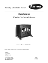
Sherborne GSL
Conventional Flue Gas Stove
Installation / Servicing Instructions
& User Manual
PLEASE RETAIN THESE INSTRUCTIONS FOR FUTURE REFERENCE
THIS STOVE IS NOT SUITABLE FOR TIMBER FRAMED PROPERTIES.
FOR USE IN COUNTRIES
GB & IE
Sherbone GSL Natural Gas With Logs Shown
Rev 3
Nov 2006
Part No. AFGS1095
NG - 32-248-06
LPG - 32-248-07
Gas Council ID Number

INSTALLATION
Safety Notices 3
General Information 3-4
Contents List & Part Identification 5
Important Notices 6
Statutory Requirements 6
Certification 6
Technical Data 7
Gas Fire Dimensions 7
Installing The Stove 7
Preparation of the stove 8
Stove Location 8
Shelf Clearances 9
Flue System 10
Fitting The Flue Spigot And Blanking Plate 11
Rear / Top Flue Options 11-12
Connecting The Gas Supply 13
Pressure Test Sequence 13
Fitting & Arranging The Coals 14-15
Fitting & Arranging The Logs NG 15-16
Fitting & Arranging The Logs LPG 16-17
Installation of Remote Control System 18-21
Commissioning The Stove 22
Fire Testing 22-23
Installation Check List 24
SERVICING
Replacement Of The Glass Frame 25-26
Burner & Valve Assembly Removal 26
Annual Service 27
Cleaning Outer Surfaces 27
Fault Diagnosis 28
Annual Service Record 29
USER INSTRUCTIONS
Lighting & Controlling The Fire 32-33
Cleaning Outer Surfaces 33
Operation of Remote Control 34-37
Important Notices 38
Statutory Requirements 38
Certification 38
Shelf Clearances 39
SPARE PARTS
General Components 40-42
Options & Accessories 43
GUARANTEE 44
Final Factory Checklist 46
2 Aarrow Sherborne GSL CF
CONTENTS

References in this manual to British Standards and
Statutory Regulations and Requirements apply only
to the United Kingdom. For Ireland the rules in
force must be used.
Before installation, check that the local distribution
conditions, nature of the gas, pressure and the
adjustment of the appliance are compatible.
The manual is an important part of the appliance
and must by law be handed to the end user on
completion of the installation.
SAFETY NOTICES
• Do not attempt to burn rubbish or any other
material in this appliance.
• Do not use the appliance if the glass is cracked or
broken.
• Do not make any unauthorised
modifications to the appliance.
• It is recommended that the stove be guarded
to protect the young and infirm using a
fireguard complying with BS8423:2002.
• Coal / Log set -The coal/log set contains
Refractory Ceramic Fibres (R.C.F), which are man
made vitreous silicate fibres. Excessive
exposure to these materials may cause
temporary irritation to the eyes, skin and
respiratory tract. Care must be taken when
handling these items to ensure the release of
dust particles is kept to a minimum. To
ensure that the release of fibre from these
items is kept to a minimum, during
installation and servicing it is recommended
that a vacuum cleaner fitted with H.E.P.A.
filters is used to remove any dust, soot or
any other debris accumulated in and around
the appliance. This should be performed
before and after the installation. It is
recommended that any replacement item(s)
are not broken up but sealed within a heavy
duty polythene bag and clearly labelled
"R.C.F. waste". This is not classified as
"hazardous waste" and may be disposed of
at a tipping site licensed for the disposal of
industrial waste. Protective clothing is not
required when handling these items but it is
recommended that gloves are worn and
normal hygiene rules are followed.
Always wash your hands before eating or
drinking.
• In the event of a gas emergency, consult the
telephone directory and ask for your local
gas supplier.
Guide to manual handling
• Always obtain assistance when lifting the
appliance.
• When lifting always keep your back
straight. Bend your legs not your back.
• Avoid twisting at the waist. It is better to
reposition your feet.
• Avoid upper body/top heavy bending. Do not
lean forwards or sideways when
handling the fire.
• Always grip with the palms of your hands.
Do not use fingertips for support.
• Always keep the stove as close to the body as
possible. This will minimise the cantilever
action.
• Use gloves to provide additional grip.
________________________________________
GENERAL INFORMATION
1. General Note
All materials and equipment used in the
installation of this stove should be fit for the
purpose, be of suitable quality and workmanship
and should comply with the applicable British
Standards, building regulations and rules in force.
2. Ventilation
No purpose provided ventilation is normally
required.
3. Flue Type
The stove is suitable for flue options with a
minimum diameter of 127mm (5”) and have a
minimum effective height of 3 metres (10ft) see
page 11 to 12.
4. Hazardous Materials
Asbestos, hazardous or any banned materials have
not been and will not be included in this product.
Aarrow Sherborne GSL CF
3
INSTALLATION INSTRUCTIONS

5. Stove location
See installation instructions on page 7.
6. Packed details
For packed weight see packaging labels.
7.Unpacking note
When the stove is unpacked ensure no damage
occurs if placed on the carpet as it can leave inden-
tation marks.
For contents list see page 5.
8. Fit for purpose
All materials, appliances and equipment used
should be fit for purpose, be of suitable quality and
workmanship and should comply with the
applicable British Standard.
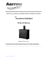
9. Data Label Plate.
The data label plate is fixed to the underside of the
valve bracket assembly, and can simply be swung
in and out as required (see Fig 2a). Please observe
the data, safety and warning labels attached to this
plate. Do not remove this plate from the stove.
Aarrow Sherborne GSL CF
4
INSTALLATION INSTRUCTIONS
Fig 1
Fig 2a
Please Observe Unpacking
& Safety Warning Labels
Stove Specification Label
(Both Ends Of Box)

ALL
TYPES
Main Box
Aarrow Sherborne GSL CF 5
INSTALLATION INSTRUCTIONS
•
•
Packed Inside Stove
Coal Set (NG & LPG) or
Log Set (NG Only) or
•
•
Log Set (LPG Only)
•
GLASS FRAME ASSEMBLY
STOVE ENGINE
DUMMY FUEL RETAINER
OUTER BODY & CANOPY
FIRE DOORS
VALVE COVER
•
•
•
•
OPERATING INSTRUCTIONS
CANOPY COVER PLATE
•
•
•
•
•
CANOPY INFILL PIECE
HOT PLATE (BLANKING)
FLUE SPIGOT
OPERATING TOOL
•
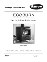
CONTENTS LIST
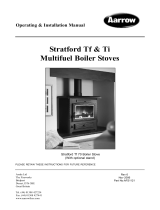
Fig 2b
Canopy Cover Plate
Canopy Infill Piece
Outer Body & Canopy
Stove Engine Assembly
Glass Frame Assembly
Dummy Fuel Retainer
Fire Doors
Valve Cover
PART IDENTIFICATION
Flue Spigot
Hot Plate (Blanking)
Operating Tool
•
GAS SERVICE TAP & GLASS SCREWS

IMPORTANT NOTICES
A qualified gas engineer must carry out the
installation and servicing of this appliance in
accordance with these instructions and in
compliance with current Building Regulations.
Such person must be a registered CORGI
engineer.
This appliance is designed to run on natural gas
(NG) or liquid petrolum gas (LPG) depending up
on the model purchased. Warning - Only use the
appliance with the specified gas.
The instructions must be read before use of the
appliance.
Please note the following;
• Sealed components must not be interfered
with.
• Servicing instructions and part identification
numbers are given towards the back of the
manual.
• Only use genuine Aarrow parts for
replacements.
• Ventilation, no purpose built ventilation is
normally required, normal adventitious room
ventilation being suffient.
• Coal / log set, see safety notice on page 3 must be
observed.
All surfaces except the control knobs are
considered to be working surfaces.
Warning: Under no circumstances must the fire
be operated if the glass is cracked or broken.
Warning: If it is known or suspected that an
operational or ignition fault exists on the
appliance, it must not be used until it has been
investigated and corrected by a qualified gas
engineer.
Warning: THIS GAS APPLIANCE MUST BE
SERVICED EVERY TWELVE MONTHS BY A
QUALIFIED GAS ENGINEER.
STATUTORY REQUIREMENTS
This product must be installed in accordance with
the rules in force.
The current Gas Safety (Installation and Use)
Regulations (as amended).
The Building Regulations for England and Wales
2000 ref Approved Document J 2002 edition
(issued by the DTLR).
The Building Standards (Scotland) (Consolidation)
Regulations.
Detailed recommendations are outlined in the
current issue of the following British Standards:-
BS5440 parts 1 and 2, BS5871 part 1 and BS6891.
Any Manufacturer's Instructions must not be
taken as overriding statutory requirements.
_________________________________________
CERTIFICATION
This appliance is CE certificated for performance
and safety. Therefore, it is important that no
alteration is made to the appliance.
Any alteration not approved by Arada Ltd will
invalidate the guarantee.
6 Aarrow Sherborne GSL CF
INSTALLATION INSTRUCTIONS

Aarrow Sherborne GSL CF 7
INSTALLATION INSTRUCTIONS
TECHNICAL DATA
Natural
Gas
Gas
Category
I2H
NOx Class
Unclassified
Table 1
Fig. 3
Efficiency
Class
CLASS 2
INSTALLING THE STOVE
A CORGI qualified gas engineer MUST install the stove
in accordance with the following regulations and stan-
dards:-
The Gas Safety (Installation and Use) Regulations
current edition.
The Building Regulations for England and Wales 2000
ref; Approved Document J 2002 edition (issued by the
DTLR).
The Building Standards (Scotland) (Consolidation)
Regulations.
BS5440 parts 1 and 2 BS5871 And these Installation
Instructions.
Warning: Failure to comply with the regulations,
requirements, or these instructions will invalidate the
guarantee and could have hazardous consequences.
IMPORTANT
Please note that in tight recesses the gas supply point
may be inaccessible. Therefore it may be necessary to
route the pipe for the gas supply before installing the
stove into its recess.
LPGGas Type
I3P
Supply
Pressure
20mbar
37mbar
Bray 82/160Bray 82/400
Injector
Max. Heat
Setting
6.1 kW
Heat Input
(gross)
Gas Rate
0.55m
3/
hour
5.7kW
0.21m
3/
hour
Min. Heat
Setting
2.5 kW
Heat Input
(gross)
Gas Rate
0.23m
3/
hour
2.5kW
0.09m
3/
hour
CLASS 2
Unclassified
Country Of
Use
AT,DK,ES,FI,
GB,GR,IE,IT,
NO,PT,SE
ES,FR,GB,
GR,IE,IT,PT
Gas Council
Id Number
32-248-06
32-248-07

PREPARATION OF THE STOVE
Prior to starting the installation and after removing
the packaging, check that all the parts have been
supplied to the contents list on page 5.
Carry out the following:-
Step 1 Remove outer casing (disengage locking
levers see page 25, steps 1a /b, 2, 3, 4, and 5).
Step 2 Remove glass and retaining frame (see page
25 step 6).
Step 3 Remove the packaging from the coal / log set
and cut the cable tie retaining 8mm olive and valve
connection nut (located to the rear of valve assem-
bly).
STOVE LOCATION
The appliance must not
be installed in a room or
space, which contains a bath or shower.
This stove is designed for use with either top or rear
flue outlets and must be mounted on a hearth. The
hearth must be strong enough to support the stove.
For overall minimum hearth sizes see Fig.4a and
Fig.4b.
To comply with current Building Regulations the
stove must stand on a fireproof hearth which has a
minimum upper fireproof layer of 12mm non-com-
bustible material. The rear of the stove is to be
100mm from the wall which must be of a non-com-
bustible material.
The hearth must not be capable of inadvertent
covering by a carpet or rug. This should be
achieved by either:
•The hearth being 50mm above the
level of the room floor.
or •a 50mm high fender or kerb being
fixed around the edge of the hearth.
Ensure the hearth is level and flat.
Do not place any combustible material including
clothing, furniture and furnishings (including
curtains) within 1 metre of the stove.
For details of combustible and non-combustible
shelf clearances see graphs 1 and 2 on page 9.
The rear edge of the canopy cover must be fitted
flush against the wall.
It is acceptable to place the stove against plaster
board on dry line property.
The stove must not be installed against a
combustible wall.
The stove must never be positioned closer than
100mm to any rear wall see Fig. 4a
The stove is NOT
suitable for houses with timber
frame construction.
8 Aarrow Sherborne GSL CF
INSTALLATION INSTRUCTIONS
Fig. 4a
Fig. 4b
Side Clearances
X=100mm Minimum Distance
Y=See Graph 1 & 2
A=100mm Minimum Per Side To A
Non Combustible Wall.
B=200mm Minimum Per Side To A
Combustible Wall.

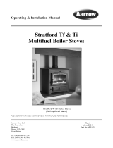
SHELF CLEARANCES
Combustible shelf clearances
The minimum height from the extreme top surface of the stove to the underside of a shelf or other
projection made of wood or any other combustible material is shown on graph 1.
Non-Combustible shelf clearances
The minimum height from the extreme top surface of the stove to the underside of a shelf or other
projection made of non-combustible material is shown on graph 2.
W
ARNING: No shelf is to be used with a top flued appliance, where it has to pass through a shelf.
Aarrow Sherborne GSL CF 9
INSTALLATION INSTRUCTIONS
Graph 1
Graph 2

FLUE SYSTEM
The stove must be connected to a suitable and
efficient flue that provides a good updraught to
safely take the products of combustion (fumes)
from the stove outlet to the outside air. To ensure a
good updraught it is important that the flue gases
are kept warm and that the flue size suits the stove.
The termination of the outlet at the top of the flue
also needs to comply with the Building
Regulations. The minimum effective height of the
chimney must be at least 3 metres and when warm
the flue draught should be between 0.05 and 6mb
(0.5mm to 6mm water gauge).
The stove requires a minimum flue size of 125mm
(5 inches). The stove can be fitted to a
sound conventional solid fuel burning chimney
system (Class 1) provided it is swept.
If the chimney is not sound or the chimney has an
internal flue size greater than 225mm (9 inches)
diameter or 200 x 200mm square, a 125mm (5
inches) diameter stainless steel flexible flue liner
complying with BS 715 should be installed in the
flue.
If a new chimney is being provided it should fully
comply with the relevant Building Regulation
Requirements and BS 5440: Part 1. Suitable types
of chimney include the following.
• Masonry chimney built with clay or concrete lin-
ers, or a chimney block system meeting Building
Regulations.
• Precast concrete gas flue block complying with
BS 1289: Part 1
Factory made metal chimney complying with BS
715 (often called "Twin wall Class 2 chimney") or
Factory made metal insulated chimney comply-
ing with BS 4543: Part 2 (often called "Class 1 pre-
fabricated metal chimney"). To ensure the flue
gases are kept warm an insulated chimney system
should be used if the chimney is positioned outside
the building.
The flue must be terminated with a suitable
chimney pot or cowl and the chimney or flue shall
be swept prior to installation unless the chimney is
clean and unobstructed.
The flue and chimney installation must be
carefully checked by a competent person before
fitting the stove to ensure it is suitable and will
work safely. The flue must also pass a Flue flow
test (smoke test) to BS 5440: Part 1.
For advice on flues and chimneys contact;
NACE (National Association of Chimney
Engineer): telephone 0800 0924019
www.nace.org.uk
or
NACS (National Association of Chimney
Sweeps): telephone 01785 811732
www.chimneyworks.co.uk
10 Aarrow Sherborne GSL CF
INSTALLATION INSTRUCTIONS

FITTING THE FLUE SPIGOT AND
BLANKING PLATE
Note: Blanking plate fitted to top flue outlet for
packing
The gas stove is designed so that the flue can be
fitted to either the top or the rear of the appliance.
Fit the flue spigot and blanking plate for either top
or rear flue outlet in accordance with figure 5a or
5b (below).
Lock the blanking hot plate in place by rotating
anti-clockwise and tighten by tapping gently with a
block of wood and mallet. Fit the spigot to the
unused opening in the same way. The units are
sealed by the attached gaskets.
CLOSURE PLATES
If a closure plate is used for sealing off the chimney
or fireplace opening it can be made of metal (e.g.
aluminium sheet) or fireplace board (see figure 6
a/b/c on page 12) however provision must be made
for checking for debris build up. Closure plates
must be sealed to the chimney or fireplace opening
with fire cement, fireproof rope or other suitable
high temperature mastic.
REAR FLUE OPTIONS
Open Hearth (See Figure 6-a page 12)
Fit and seal a ‘T’ section (with debris /soot
collector) directly into the flue spigot. Ensure it
passes through the closure plate by at least 102mm
(4”).
The maximum horizontal section allowed is
350mm.
Provide a minimum vertical height of 600mm of
flue from the height of the rear flue outlet.
Closure Plate (See Figure 6b page 12)
Connect the flue spigot to the rear outlet then
connect a flue extension to the spigot up to a
maximum length of 350mm.
Fit and seal the closure plate into the fireplace
opening.
Position the stove so the flue extension passes
through the hole in the closure plate by at least
50mm.
Ensure all joints are sealed with fire cement or a
suitable high temperature sealant.
TOP FLUE OPTIONS
Top Flue (
See Figure 6c page 12)
Provide a minimum vertical height of 600mm of
flue measured from the top of the appliance.
Position the stove, with flue spigot in place, into
position under the flue and seal the spigot/flue
connection with fire cement or a suitable high
temperature sealant.
It is recommended that a smoke test is performed
inside the stove to ensure that adequate flue draw is
evident after making the flue connection
Aarrow Sherborne GSL CF
11
INSTALLATION INSTRUCTIONS
Fig 5c
Fig. 5a
Fig. 5b

12 Aarrow Sherborne GSL CF
INSTALLATION INSTRUCTIONS
Fig. 6b
Fig. 6a
Fig. 6c.
Y=See Graph 1

CONNECTING THE GAS SUPPLY
Once the stove is in place it is then possible to
connect the gas supply. The gas supply point is
located centrally at the rear (as show in fig.7) and
should be connected in accordance with the follow-
ing requirements.
Fig. 7
Check that the appliance is suitable for the gas
supply; refer to data labels on packaging and/or the
stove data label for the gas type.
The gas installation must be in accordance with the
current issue of BS6891.Gas supply pressure at the
fire should be 20mbar for natural gas & 37mbar
for LPG.
The gas supply should be connected with the 12mm
fitting and olive supplied with the stove.
A maximum pipe run of 1.5 meters (or 5 feet)
should be adhered to. Copper tubing may be used
provided a distance of 25mm is maintained
between pipe-work and any surface of the stove.
The gas service tap (supplied) should be fitted adja-
cent to the fireplace to enable safe removal of the
appliance for servicing. After fitting the supply,
operate the gas tap (supplied) and check all joints
up to the termination of the supply pipe for gas
tightness using a soap/water solution and the pres-
sure drop method.
To check the pressure to the burner. This must be
carried out with all other gas appliances operating
at maximum. To check the pressure to the burner it
is necessary to ignite the appliance and set to 'high
rate'. (See pressure test sequence).
Fig. 8
PRESSURE TEST SEQUENCE
Controls are located at the base of the stove below
the ash lip.
Ensure supply is isolated and the valve is in
the off position
Step 1. Remove the valve control cover by
unscrewing the pozi screw located by knob B and
lever the retaining tab to the side of knob A.
Step 2. Locate the outlet pressure tap and unscrew
approximately half a turn anti-clockwise with a
small flat bladed screw driver. Connect a pressure
guage to the outlet pressure tap.
Step 3. Re-connect the supply and light stove. (see
lighting and controlling the stove section in the
users instructions section of this manual). Turn to
high setting. Read pressure guage, setting to be -
20 mbar for Natural Gas or
37 mbar for LPG
Step 4. If any adjustment is required, use the brass
screw located between knob B and knob A on the
front of the valve, and adjust accordingly to the
indication symbol marked upon the valve body.
Step 5. Turn off stove and isolate the supply.
Step 6. Disconnect manometer and re-tighten the
outlet pressure tap screw. Do not over tighten.
Step 7 Replace the valve control cover.
Aarrow Sherborne GSL CF 13
INSTALLATION INSTRUCTIONS
Gas Inlet
Rear Of
Valve

FITTING AND ARRANGING THE
COALS (Both NG & LPG versions)
Ensure the appliance is cold
Safety Notice - Please see SAFETY NOTICES
ref. Coal / Log sets page 3.
Warning: The coals and the coal matrix are fragile
ensure they are handled carefully.
Ensure location is correct. Do not force the matrix
into position. If the coals and/or the coal matrix are
damaged they must be replaced with genuine
Aarrow parts.
Warning: An incorrect coal layout may cause soot
to build up inside the stove and therefore invalidate
the guarantee.
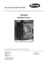
How to arrange the coals
(see Fig 9 for part identification)
1) Place the 2x larger base matrices at the rear of
the burner. These are labelled LR (left rear) & RR
(right rear). These should be positioned so that the
slots in the matrices sit over the rear upright fold of
the burner top plate.
2) Next position the 2x smaller base matrices
between the rear matrices and the front of the fire-
box. These matrices are labelled, LF (left front) &
RF (right front). The RF matrix has a notch in the
front to avoid the pilot assembly.
The arrangement should look like Fig 10a.
3) Now position one of the loose coals into the
centre of the stove ensuring that it is placed into
the centre cutout and when in position, this coal
will be resting upon the four corners of the base
matrices. See Fig. 10a & b.
4) Next, take 6x coals and place along the front
row of the base matrices, 3x to the left of the cen-
tre coal and 3x to the right of the centre coal.
Observre the cutout positions within the matices
as shown in Fig. 10b & 10c.
5) Take the remaining 4x coals and place along
the upper edge to the base matrices. Again, place
the coals into the areas shown in Fig 10b. The
coal set layout is now complete and should look
like Fig 10d & 10e.
14 Aarrow Sherborne GSL CF
INSTALLATION INSTRUCTIONS
Fig. 9
RR
RF
11X
LOOSE
COALS
LF
LR
Fig. 10a
Pilot
Notch
Centre Coal
Position
Fig. 10c
Fig. 10b
Plan View Of Base Matricies - White Dots
Indicate Loose Coal Positions / Cut outs.

Plan View Of Coal Set Layout.
Note - Ensure that the pilot light is visible through
the slot in the front right base matrix and that the
pilot flame is not impinged.
FITTING AND ARRANGING THE
LOGS (NG ONLY)
Ensure the appliance is cold
Safety Notice - Please see SAFETY NOTICES
ref. Coal / Log set, page 3.
Warning: The logs and matrix are fragile, ensure
they are handled carefully.
Ensure location is correct. Do not force the matrix
into position. If any of the logs and/or rear matrix
is damaged, they must be replaced with genuine
Aarrow parts.
Warning: An incorrect log layout may cause soot
to build up inside the stove and therefore invali-
date the guarantee.
Key For Contents To NG Log Set -
A = Rear log matrix (black in colour)
B = Loose Embers (bagged)
C = Curved Log
D = Y Shape Log
E = Central Log (Knotted Lump Protruding)
F = 3x Small Twigs
G = 1x Large Twig
How to arrange the logs
1) Position the rear log matrix in the centre at the
rear of the burner. The base of the matrix should
slot down behind the burner. See Fig. 12a.
2) Lay the Y shape log to the right hand side of
the burner. Ensure that the Y open section is upper
most and is resting onto the cutout flat area to the
right of the rear log matrix. The base should be
approimately 30mm from the front of the stove
window opening. See Fig 12a.
3) Take the curved log and place this to the left
hand side of the burner. Make sure that the base of
this log is again approx. 30mm from the front of
the stove and the upper end of the log is resting on
the grooved notch within the rear log matrix. See
Fig 12a. Note, there should be a gap between both
side logs when resting correctly on the rear
matrix.
4) Next scatter the loose embers onto the burner
area. Take care not to obstruct the pilot assembly.
5) Lay the central log, from the centre front of the
burner to the rear of the stove. Sitting the upper
portion of the central log onto the edge of the
Aarrow Sherborne GSL CF 15
INSTALLATION INSTRUCTIONS
Fig. 10d
Fig. 10e
Fig. 11
A
B
D
G
E
C
F
Fig. 12a

upper corner of the curved left hand log. See Fig.
12b. Note, the top resting position of the central
log is angled to the left.
6) Place 2x smaller twigs as shown in Fig. 12b.
Note, the bottom of the twigs rest between the
stove body and burner. Take care with the right
hand twig to avoid impinging upon the pilot
assembly.
7) Take the remaining small twig and large twig
and place as shown in Fig 12c. The log layout is
now correct.
FITTING AND ARRANGING THE
LOGS (LPG
ONLY)
Ensure the appliance is cold
Safety Notice - Please see SAFETY NOTICES
ref. Coal / Log set, page 3.
Warning: The logs and matrix are fragile, ensure
they are handled carefully.
Ensure location is correct. Do not force the matrix
into position. If any of the logs and/or rear matrix
is damaged, they must be replaced with genuine
Aarrow parts.
Warning: An incorrect log layout may cause soot
to build up inside the stove and therefore invali-
date the guarantee.
Key For Contents To LPG Log Set -
A = Y Shaped Rear Log
B = Loose Embers
C = Curved Log
D = Straight Log
E = 1x Medium Twig
F = 3x Small Twig
G = 2x Large Twigs
How to arrange the logs
1) Position the Y shaped log across the rear of the
burner, standing up against the rear of the firebox
and behind the burner. See Fig. 14a.
2) Scatter the loose embers over the burner, taking
care not to cover the pilot assembly. See Fig. 14a.
16 Aarrow Sherborne GSL CF
INSTALLATION INSTRUCTIONS
Fig. 12b
Fig. 12c
Fig 13
B
A
G
E
F
D
C

3) Place the curved log to the left hand side of the
firebox, rest the top of this log onto the top of the
Y shaped open end of the rear log. Take the
straight log and position this to the right hand side
of the firebox, again rest the rear of this log onto
the rear Y shaped log, opposite end to the curved
log. Note, rest both fronts of these end logs
against the front corners of the burner.See Fig.14b.
4) Next place the 2x large twigs into the layout
with the base of each twig central about the stove
opening and placed to the front of the stove. The
tops of these twigs radiate out from the base to
form a vee shape and rest upon the rear Y log (left
hand) and straight log (right hand). The medium
twig is placed between the large twigs as shown in
Fig. 14c.
5) The remaining 3X small twigs are placed as
shown in Fig. 14d. The LPG log layout is now
complete.
Aarrow Sherborne GSL CF 17
INSTALLATION INSTRUCTIONS
Fig. 14a
Fig. 14b
Fig. 14c
Fig. 14d

NOTE: If the optional remote control system has been ordered with the stove and is not
fitted please proceed.
FOR A
MANUAL STOVE (WITHOUT REMOTE CONTROL) PROCEED TO PAGE 22.
INSTALLATION OF REMOTE CONTROL SYSTEM
Important
• A corgi registered gas engineer must carry out the installation of the remote control system
P
AR
TS LIST
1 Motor
2 Ultrasonic Receiver
3 Remote control handset
4 Wiring Harness (Multiblock end to reciever, spade connections to motor/micro switch)
5 Micro-switch
6 AA/LR6 1.5v Batteries (4x) & 9V-6F22 9v Battery (1) Supplied (Not Shown)
Technical data
Ambient temperature range Remote and receiver max. 140deg F / 60deg C
Connecting cable max. 356deg F / 180deg C
Batteries Quality Alkaline Handset: 1x9V Block
Receiver: 4x1.5V AA
18 Aarrow Sherborne GSL CF
INSTALLATION INSTRUCTIONS
1
2
3
5
4
Fig. 15

ASSEMBLE MOTOR
1) Remove the front cover from the valve. This is done by unscrewing the small pozi screw, located by
knob B. Unclip the right hand side of the cover located to the side of knob A. See Fig. 16a & b.
2) Remove the cover and dispose of the spacer tube fitted with the screw.
3) Position the motor onto the location lugs (arrow X) and engage the drive gear onto knob B (arrow Y).
4) Replace valve cover, ensure clip is located before the pozi screw is tightened. Do not over-tighten the
screw as this may effect the operation of the control.
5) Take the micro switch and fix to the front of the valve cover with the self tapping screw provided.
Switch is located onto the lug moulded within the valve cover, next to knob B. See Fig. 16e.
Aarrow Sherborne GSL CF 19
INSTALLATION INSTRUCTIONS
Fig. 16a Fig. 16b
Fig. 16d
Fig. 16c
X
Fig. 16e
Knob A
Knob B
Screw
Tab
Y
Knob B
Wiring
Connections
Micro Switch

ASSEMBLE RECEIVER
Important
The remote system is intended for use with original Aarrow parts only.
1) Carefully push the multi block connector on to the connection within the reciever unit as shown in Fig
17a. This connector can only fit one way, so ensure the slot in the recievers board lines up with the mould-
ing within the multi block connection.
2) Next, connect the angled spade connectors to the motor, note there are two different sized connectors and
these can only be fitted to the appropriate sized spade tab. The remaining narrow spade connectors fit to the
spade tabs on the micro switch. These are not handed, see Fig. 17b.
3) Place the double sided adhesive tape to the underside of the reciever unit. Slide back the cover and insert
the 4x AA/LR6 1.5v batteries into unit, observing the correct polartity as marked on the unit. Re-place
cover. Fig. 17c.
CAUTION! Ensure the batteries are inserted AFTER the motor is wired. A short circuit can
destroy the electrical components.
4) Position the reciever unit, as shown in Fig. 17d onto the space provided on the valve bracket. Affix the
underside of the unit with the double sided tape. Take care to route the wiring harness away from any hot
parts and do not obstruct the valve controls. The reciever unit works by ultrasonic so ensure that the reciev-
ing round grill is facing to the front of the stove.
20 Aarrow Sherborne GSL CF
INSTALLATION INSTRUCTIONS
Fig. 17a
Fig. 17b
SLOT
Fig. 17c
Fig. 17d
/