Page is loading ...

Dry stove installation guide
BK545 REV 14
BS EN 13240:2001 +A2:2004
BS EN 13229:2001 +A2
Issue Date: 15/09/2022
Suitable For Freestanding
and Inset Appliances
FREESTANDING INSET
22

Page 2 BK545 Rev 14
Dry Stove Installaon Guide
Please carefully read through the enrety of this installaon guide before commencing installaon.
Should you have any quesons about our stoves that are not covered in this manual, please contact
the Arada retailer in your area, or call our technical support department on +44 (0)1297 632052.
Arada has a policy of connuous product development and therefore we reserve the right to amend
specicaons without prior noce.
Please check with your retailer or dealer if you are unsure about any aspect of your stove, its
installaon or correct use.
Arada Dry Stove Installation Guide

BK545 Rev 14 Page 3
Dry Stove Installaon Guide
Page No.
INTRODUCTION
Warnings ............................................................. 4
Health and Safety ................................................ 4
INSTALLATION REQUIREMENTS ...................... 5–7
Hearths and Recesses ......................................... 5
Combusble Materials ........................................ 6
Air for Combuson ........................................... 6–7
FLUES AND CHIMNEYS .................................... 7- 8
INSTALLING THE STOVE ................................... 9–12
Removing the door ............................................. 9
Removing the throat plate and liners ................. 9
Assembling the grate bars ................................. 9
Fing the spigot outlet to the stove ................. 10
Connecng the spigot outlet to the
ue system ......................................................... 10
Sealing of terminals ............................................ 10
Inset stove specic instrucons ......................... 10
Inset stoves ue connecon ............................... 10
Adjusng the self-levelling feet
(Cam style) ......................................................... 11
Adjusng the self-levelling feet
(Levelling screw style) …………………………………….11
Firebox liner panels .......................................... 12
COMMISSIONING THE STOVE .......................... 13
Contents

Page 4 BK545 Rev 14
Dry Stove Installaon Guide
Warnings
It is a legal requirement that the installation of all new
or replacement, wood or solid fuel heating appliances
obtain Building Control approval from your local
authority. This can be done by using a qualified
heating engineer, affiliated to a government approved
Competent Persons Scheme such as those listed on
www.gov.uk/building-regulations-competent-person-
schemes
You can also consult your local buildings inspector /
controller.
All local regulations, including those referring to
National and European standards, need to be
complied with when installing the appliance.
Refer to the current issue of BS 8303 code of practice
for the installation of domestic heating appliances
burning solid mineral fuel.
This stove should not be installed into a chimney that
serves any other heating appliance.
Any manufacturer’s instructions must not be taken as
overriding statutory requirements.
Arada Ltd will not be responsible for any
consequential or incidental loss or injury however
caused.
Health and safety
Before any installaon work is undertaken
consideraon must be given to the Health and Safety
at Work Act 1974. Safe working pracces should be
followed at all mes.
Please consult health and safety guidelines for advice
on handling heavy and/or large items.
During installaon ensure that adequate precauons
are taken to avoid unnecessary risk to yourself or any
householder.
The danger from the causc nature of re cement,
should be avoided by using these accepted methods:
Wear gloves when handling re cement. Wear goggles
when chiselling or looking up chimneys.
This stove contains no asbestos. If there is a possibility
of disturbing any asbestos in the course of the
installaon then please seek specialist guidance and
use appropriate protecve equipment.
Any further warnings in this document will be
marked out in a box such as this one. Ignoring the
warnings could lead to damage/injury to persons
and/or property.

BK545 Rev 14 Page 5
Dry Stove Installaon Guide
Hearths and Recesses
The stove should be installed on a surface with
adequate load bearing capacity. If the exisng
construcon does not meet this prerequisite, suitable
measures (e.g. load distribung plate) should be taken
to achieve it. Please pay parcular aenon when
examining exisng building work for suitability to
meet the following requirements.
When installing an inset stove, hearths should have a
suciently at surface to allow a good seal to the
stove body to be created during its installaon.
Stonework, uneven bricks etc., may need further work
to ensure that this can be achieved. Any voids behind
an inset stove should be lled with vermiculite or
similar.
The stove should be installed on a non-combusble
surface not less than 12mm thick (conforming to
Building Regulaons unless otherwise specied) of
suitable load bearing capacity and heat resistance.
Allowances should be made for the expansion and
contracon of any materials which are ed up to and
near the appliance.
If required, the dimensions of any construconal
hearth for all stoves should project at least 500mm
forward of the front of the appliance and 150mm at
the sides. The surface of the hearth should be free of
combusble materials. The superimposed hearth for
all installaons should project at least 225mm forward
from the front of the appliance and 150mm either side
of the edge of the appliance.
In most buildings with solid concrete or stone oors,
the requirement will be met by the oor itself, but
mark the hearth to ensure oor coverings are kept
well away or use dierent levels to mark the hearth
perimeter.
Please be aware that hot air can cause staining above
the re in a similar fashion to walls above radiators.
To help prevent this and cracking we recommend that
any plaster above the re should be ed with
reinforcing expanding mesh for at least 220mm above,
and the full width of the re. You should also use a
suitably heat resistant plaster which should be
allowed sucient me to fully dry before using the
stove or cracking is likely to occur
Installaon requirements

Page 6 BK545 Rev 14
Dry Stove Installaon Guide
Combusble Materials
Please view the product sheet which accompanied
your stove for specic minimum distances to
combusble measurements.
Ideally, adjacent walls should be of suitable non-
combusble construcon, preferably brickwork.
In large replaces take care that any supporng beam
is protected by a 13mm sheet of heat resistant re
board spaced 12mm o the surface with strips of non-
combusble material. Make sure that there is a gap
between an un-insulated ue system and any
combusble material. This gap must be at least 3X the
outside diameter of the ue pipe, or 1.5X the ue
diameter to non-combusble surfaces. Please consult
the ue manufacturers specicaon for insulated
ues.
Air for combuson
All stoves require venlaon to burn safely and
correctly. There are a number of requirements that
need to be met when installing a stove, for example,
allowing for the permeability of the house (air
permeability is the general seepage of air into the
house via air vents, doors and windows etc.)
There must always be a permanent means of
providing air for combuson into the room in which
the stove is installed. Air starvaon will result in poor
ue draw and may cause smoke to leak into the room.
For all installaons it is recommended that a
permanent vent with a total free area of at least
550mm2 for every kW above 5kW should be
connected directly to the outside air. Installaons in
properes built aer 2008 should have their vent
increased by a further 330mm2 for each of the rst
5kW. Alternavely this air can be supplied through an
external wall of an adjacent room, which itself has to
be connected to the room the appliance is installed by
a permanent vent of the same size.
Note: If the appliance is ed with a draught stabiliser
(or if one is ed to the ue pipe or chimney in the
same room as the appliance) then the permanent air
entry opening (or openings) should be increased by
300mm2 for each kW of rated output up to 5kW and
an addional 850mm2 for each kW output over 5kW.
If there is more than one appliance in the property
then each appliance must be supplied with adequate
Installaon requirements / Flues and Chimneys

BK545 Rev 14 Page 7
Dry Stove Installaon Guide
combuson air so that all appliances can be lit
simultaneously.
The posioning of any air vent must be so that it
cannot be liable to blockage or obstrucon. Ideally it
should also be posioned where it is unlikely to cause
a cold draught. It should not be posioned in the
replace recess.
For more detailed guidelines on required venlaon
sizes please refer to the Document J Building
Regulaons (Combuson Appliances) at the
www.planningportal.gov.uk website.
If you plan to use an external air supply on a suitable
stove, and have bought the appropriate Arada
External Air Supply Kit, please refer to the instrucons
included with the kit on how to install it.
The accompanying stove technical product sheet
states whether or not your appliance is compable
with a Direct Air Supply Kit.
Flues and Chimneys
The stove must be connected to a suitable and
ecient ue so that products of combuson (fumes)
from the stove are expelled to the outside air. Please
remember that chimney draught is dependent on four
main factors :
Flue gas temperature
Flue height
Flue size
Flue terminal
To ensure a good up draught it is important that the
ue gases are kept warm and that the ue size suits
the stove. The terminaon of the outlet at the top of
the ue also needs to comply with Building
Regulaons. The minimum eecve height of the ue
must be at least 4.5 metres from the top of the stove
to the top of the ue outlet. When warm the ue
draught should be between 0.1 to 0.2mb.
The draw of a chimney / ue can vary in dierent
weather condions and the customer should be made
aware of this. Failure to correct an over-drawing ue
will invalidate the warranty.
A chimney may comply with regulaons but could sll
be subject to down draught and similar problems. A
chimney terminang above the ridge level is generally
less likely to suer such problems.
If a new chimney is being provided it should fully
comply with the relevant Building Regulaons that
specify the requirements for solid fuel burning
installaons. Suitable types of chimney include the
Flues and Chimneys / Installing the stove

Page 8 BK545 Rev 14
Dry Stove Installaon Guide
following :
Masonry Chimney: Built with clay or concrete
liners, or a chimney block system meeng
Building Regulaons. These types of chimneys
should be installed in accordance with the
Building Regulaons and BS EN 15287-1:2007.
Factory Made Insulated Chimney: Complying
with BS 4543:Part 2 (oen called Class 1
prefabricated metal chimney). These types of
chimneys should be installed in accordance with
Building Regulaons and BS EN 15287-1:2007.
Due to the gradual introducon of European Chimney
Standards chimneys will be specied according to
their performance designaon as dened in BS EN
1443 that covers the General Requirements for
chimneys. The minimum performance designaon
required for use with solid fuel burning stoves is T450
N2 S D3.
The ue and chimney installaon must be carefully
checked by a competent person before ng the
stove to ensure it is suitable and will work safely.
If the chimney is old (i.e.: built of brick or stone
without a liner) or being opened up for reuse
addional checks and smoke tesng as described in
Appendix E of the Approved Document J 2010 Edion
should also be carried out to ensure the ue and
chimney are in good operang condion.
Check the exisng ue is in good condion with
suitable access for collecon and removal of debris.
It is also important that suitable ue pipe
(recommended at least 600mm in length) complying
with the Building Regulaons is used to connect the
stove to the ue in the chimney. Suitable access
should be provided into the ue for regular inspecon
and sweeping of the ue ways.
The installer should comply with Building Regulaons
requirements in respect of providing a Noce Plate
giving details on the chimney, ue lining, hearth and
replace installaon.
Chimneys should be as straight as possible. Horizontal
runs should be avoided except where the rear outlet
of the appliance is used, in which case the horizontal
secon should not exceed 150mm in length. If
necessary a combinaon of 45° and 90° bends can be
used as long as the sum of their angles is not greater
than 180° in total. i.e. four 45° bends, or two 45° and
a 90° bend.
If the stove appears to be working hard but produces
very lile output to the room it is likely that excess
draw is present in the chimney, and that heat is being
sucked out of the appliance and up the chimney. If
this is the case we recommend the ng of a draught
stabiliser in preference to a ue damper, in the
interest of safety and eciency.
Installing the stove

BK545 Rev 14 Page 9
Dry Stove Installaon Guide
Installing the stove
To make the stove easier to manoeuvre (and safer) we
recommend you remove the following parts which can
then be reed when the stove is in its nal posion:
Grate Bars
Liners
Door (To help prevent the glass from breaking)
Operang Tool
Ash pan
Throat Plate
Removing the door
Open the door so that it is perpendicular to the stove
body and then carefully li the stove door upwards o
its hinges. To replace the door reverse the instrucons
above.
Removing the throat plate
and liners
The throat plate rests on liners and (in some models) a
terary air bar. With the re door removed or open,
push up on the throat plate with the palm of one
hand. With the other, remove the side liners and then
lower the throat plate forward. It is easier to lower
one side of the throat plate rst to help remove it
from its posion and to allow it to t through the
opening of the stove. Once the throat plate has been
removed you can also remove the rear liner(s). To
replace the liners/throat plate follow the steps above
in reverse.
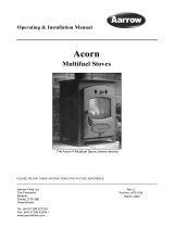
Assembling the grate bars
In a mul fuel stove the grate comprises of a series of
cast iron grate bars, seated on a pair of combs. All bars
in the grate are idencal.
In stoves with a riddling grate system the bars should
be seated with every other bar rotated 180 degrees,
so the ends marked ’H’ and ’L’ alternate on each
comb. When assembling the grate, t bars to the low
secons of the comb rst by seang the ends marked
’L’ onto the low part of the comb, whilst the ends
marked ’H’ should then be seated on the high
secons.
In stoves with non-riddling grate systems the grate is
assembled with the ends of the bars marked ’H’ sing
on the front comb, and the ends marked ’L’ sing on
the rear comb.
Installing the stove
Figure 1: Bars shown seated on their comb outside the stove.

Page 10 BK545 Rev 14
Dry Stove Installaon Guide
Fing the spigot outlet to the
stove
The ue outlet spigot and hot plate (blanking plate)
can be found packed inside the appliance and must be
ed during installaon*.
(*Only applicable to freestanding appliances).
Smear a very thin layer of re cement or use the
supplied self adhesive rope seal on the mang faces of
the ue outlet and the hot plate. Fit the outlet to the
appliance in the desired posion.
Inset models have a single ue outlet and no blanking
plate.
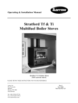
Connecng the spigot outlet to
the ue system
The flue pipe must be fitted inside the outlet spigot as
shown in Figure 2. Failure to do so could result in the
spillage of condensation running down the flue.
Fire cement should be used to create an airtight seal
between the flue and spigot.
Sealing of terminals
If an add in boiler is not to be fitted, please ensure
that any partially cut circular terminals (located on the
rear of the appliance) are sealed with fire cement,
thus preventing surplus air entering the firebox,
resulting in lower efficiency and poor fuel
consumption.
Inset stove Specic Instrucons
All inset stoves, are designed to be ed in a ‘builders
opening’ and not a chair brick. A suitable ‘builders
opening’ will be required to facilitate installaon,
observing the relevant building standards in
regulaon, especially paying aenon to the locaon
and posioning of the lintel.
Inset stove ue connecon
We strongly advise the connection of the inset stove
onto a flexible flue liner (System Flue).
The reasoning for this, is to ensure the stove operates
correctly and at maximum efficiency, maintaining a
sound air tight seal for the flue connection and thus
preventing products of combustion being emitted to
the dwelling.
Please note the importance, for any voids surrounding
an inset stove, must be filled with fire cement,
vermiculite granules or mineral wool when installed
for the interest of safety and heat efficiency .
Installing the stove
Figure 2: Fing the ue pipe inside the spigot collar
Flue Pipe
Spigot
Flue Pipe
Inside Joint

BK545 Rev 14 Page 11
Dry Stove Installaon Guide
Adjusng the self-levelling feet
(Cam style)
If applicable, adjustment is as follows:
Position the stove on the hearth into its final
resting place.
On the rear leg of the stove, loosen the pozi
screw, and rotate the inner ‘cam’ shaped
levelling foot until this touches the hearth.
Re-tighten the pozi screw. Check the stove is
level with a spirit level.
Repeat for the other rear leg.
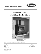
Adjusng the self-levelling feet
(Levelling screw style)
If your stove model is factory fitted with the screw
style, self levelling feet, then please follow the
procedure below. Please note, an adjuster is fitted at
each corner to allow the stove to be independently
adjusted.
Position the stove on the hearth into its final
resting place.
Using a 8mm open spanner, unscrew the
levelling foot until this touches the hearth.
Repeat for the remaining other corners.
Using a spirit level adjust until the stove canopy
is horizontal side to side and front to back.
Installing the stove
Levelling
Screw Foot
Retaining Screw

Page 12 BK545 Rev 14
Dry Stove Installaon Guide
Firebox liner panels / ‘liners’
Most Arada stoves use firebox liner panels to the sides
and back. Some Villager wood burners also have
firebox liners in the base of the stove. For detailed
fitting instructions for Villager stoves please refer to
www.aradastoves.com/support.
Stoves which are being fitted with an add-in boiler
should have the rear liner removed to create the space
in which the boiler is fitted.
For the majority of Arada stoves, the throat plate sits
on top of the side and rear panels. These should come
fitted to your stove, if however they are not, proceed
as follows to fit them:
Remove the fuel retainer.
Set the small liner(s) into the back of the firebox.
Insert the side liner panels.
Fit the throat plate with the single bend and two
cut outs to the front facing up. The projecting
lugs sit on top of the side liners. The long centre
tab on the back edge rests on the rear liners.
Replace the fuel retainer.
Installing the stove

BK545 Rev 14 Page 13
Dry Stove Installaon Guide
Commissioning the stove
Before handing over the installaon to the customer it
is a requirement under Document J (of the Building
Regulaons for England and Wales) that the appliance
is lit and the funconing of the chimney system is
checked for sasfactory operaon.
Be sure that the chimney is operang and all
smoke and fumes are vented to the atmosphere
through the chimney terminal.
Check all joints and seals.
Clean the outside of the cold appliance with a
lint free cloth or shoe brush to prevent any stains
becoming burnt on.
Check the ue draught which should read 10 -
20pa, or 0.1 - 0.2 mbar.
Consult a suitably qualied person who will have
the knowledge and equipment to perform a test.
For a registered Competent Persons scheme (such as
those referred to at www.gov.uk/building-regulaons-
competent-person-schemes ), please complete a
Cercate of Compliance, which is used for checking
and reporng the installaon as imposed by the
Government.
Otherwise please ensure the installaon is approved by
your local building control ocer.
Ensure a Carbon Monoxide alarm is ed. This
must be between 1m to 3m from the appliance,
and approximately 150mm below the ceiling
level.
A reguard conforming to BS 8423:2010
+A1:2016 should be used in the presence of
children or inrm people.
A noce plate should be provided containing
informaon on the performance characteriscs
of the hearth, replace, ue or chimney.
Explain the following to the customer:
How to operate the riddling mechanism
and air control lever.
The importance of an adequate air supply
to the room.
The importance of regularly having the
chimney swept / inspected.
That a protecve glove should be used
when operang the stove.
How changes in the weather can aect the
performance of the stove.
Using the correct fuels
If burning wood, ensure that is well
seasoned or has a moisture content of less
than 20%.

14 Dry Stove Installaon Guide — BK545 Rev 14
NOTES
Arada Ltd, The Fireworks, Weycro Avenue, Axminster, Devon. EX13 5HU United Kingdom
Tel: +44(0)1297 632052 www.aradastoves.com
/