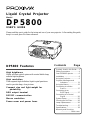
Proxima DP5800 User manual
- Category
- Data projectors
- Type
- User manual
This manual is also suitable for

Symbols Used in this Guide ... 3
Safety Precautions .................4
Your DP5800 Projector ...........6
Installation ..............................8
Using the Projector.................9
Projector Messages and
Indicators.................... 11
Using the Menus ..................12
Connecting to a Video
Source.........................17
Connecting to an
RGB Signal ................. 17
Connecting to a Control
Signal ..........................20
System Setup ....................... 25
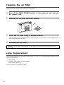
Cleaning the Air Filter........... 26
Lamp Replacement .............. 26
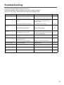
Troubleshooting ....................27
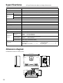
Specifications ...................... 28
Warranty and Servicing
..................... Back cover
Contents Page
DP5800 Features
High brightness
Highly efficient optical system with a metal halide lamp
ensures high brightness.
High resolution
Three separate high-definition liquid crystal panels are
used to provide sharp, clear pictures.
Compact size and light weight for
portability
RGB output terminal
RS232C communication
Mouse emulation
Power zoom and power focus
Liquid Crystal Projector
Model
DP5800
USER’S GUIDE
Please read this user’s guide for fast setup and use of your new projector. After reading this guide,
keep it in a safe place for future reference.

2
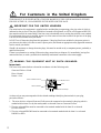
For Customers in the United Kingdom
THIS PRODUCT IS SUPPLIED WITH A TWO-PIN MAINS PLUG FOR USE IN MAINLAND EUROPE.
FOR USE IN THE U.K., PLEASE REFER TO THE NOTES ON THIS PAGE.
IMPORTANT FOR THE UNITED KINGDOM
The mains lead on this equipment is supplied with a moulded plug incorporating a fuse, the value of which is
indicated on the pin face of the plug. Should the fuse need to be replaced, an ASTA or BSI approved BS 1362
fuse must be used of the same rating. If the fuse cover is detachable, never use the plug with the cover omitted.
If a replacement fuse cover is required, ensure it is of the same colour as that visibe on the pin face of the plug.
Fuse covers are available from your dealer.
DO NOT cut off the mains plug from this equipment. if the plug fitted is not suitable for the power points in
your home or the cable is too short to reach a power point, then obtain an appropriate safety approved extension
lead or consult your dealer.
Should it be necessary to change the mains plugs, this must be carried out by a competent person, preferably a
qualified electrician.
If there is no alternative to cutting off the mains plug, ensure that you dispose of it immediately, having first
removed the fuse, to avoid a possible shock hazard by inadvertent connection to the mains supply.
WARNING: THIS EQUIPMENT MUST BE EARTH GROUNDED
Important:
The wires in the mains lead are coloured in accordance with the following code:
Green and Yellow = Earth
Blue = Neutral
Brown = Live
As these colours may notorrespond with the colured markings identifying the terminals in your plug,
proceed as follows:
1. The wire which is coloured Green and Yellow must be connected to the terminal in the plug which is
marked with the letter E or by the earth symbol or coloured Green or Green and Yellow.
2. The wire coloured Blue must be connected to the terminal marked with the letter N or coloured
BLUE or BLACK.
3. The wire coloured BROWN must be connected to the terminal marked with the letter L or coloured
BROWN or RED.
Brown to Live
Green & Yellow to Earth
Blue to Neutral
Fuse
Cord Clamp

3
WARNING: This equipment has been tested and found to comply with the limits for a Class A digital
device, pursuant to Part 15 of the FCC Rules. These limits are designed to provide reasonable protection
against harmful interference when the equipment is operated in a commercial environment. This equipment
generates, uses, and can radiate radio frequency energy and, if not installed and used in accordance with the
instruction manual, may cause harmful interference to radio communications. Operation of this equipment
in a residential area is likely to cause harmful interference in which case the user will be required to correct
the interference at his own expense.
Instructions to Users:
This equipment complies with the requirements of FCC (Federal Communication Commission) Class A
equipments provided the following conditions are met.
(1) Video signal cables:
Double shielded coaxial cables (so called FCC shield cable) must be used and the outer shield must be
connected to the ground. Or, if normal coaxial cables are used, the cables must be enclosed in metal pipes
or in a similar way to reduce interference noise radiation.
(2) Power cord:
Shielded power cord must be used. The outer shield must be connected to the ground.
(3) Video inputs:
The input signal amplitude must not exceed the specified level.
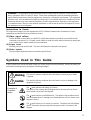
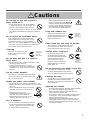
The mark indicates a Warning (or Caution).
The details of the warning (the left diagram shows the caution for an electric
shock hazard) are shown in the diagram.
The
mark indicates a prohibited action. The details of the prohibited action
(the left diagram shows a warning not to disassemble the unit) are shown in the
diagram or near it.
The
mark informs you of actions you must do. The details (the left diagram
shows “Disconnect the power plug from the power outlet”) are drawn in the
diagram.
Examples of
illustrated
marks
This symbol indicates conditions that could result in serious injury or death
if ignored.
This symbol indicates conditions that could result in injury or damage to the
equipment if ignored.
Caution
Warning
Symbols Used in This Guide
Various symbols are used in this guide to help you use the product correctly and safely, and also to protect you
and others from danger and your property from being damaged.

4
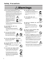
If any unusual performance occurs.
•
An abnormal smell or smoke may indicate the possibility
of fire or electric shock, etc. When any unusual
performance is observed, immediately turn off the power
switch and pull out the power plug from the power outlet.
Check that there is no smoke, etc., and then contact your
dealer to repair the unit. Do not repair it yourself .
•
Do not use this unit as it is after
trouble has occurred, such as “No
picture”,“No sound”, “Abnormal
sound”, etc. This may cause a fire,
electric shock, etc. In this case
immediately turn off the power
switch and disconnect the power
plug, then contact your dealer to
repair the unit.
•
If water, etc. enters inside the unit, turn off the power
switch of the unit first and then disconnect the power plug
and contact your dealer. If you use it as it is, it may cause
fire, electric shock, etc.
Do not install this unit in an
unstable place.
•
Avoid placing the projector in an unstable
place such as weak base, inclined floor, etc.
This may cause it to drop or fall over, resulting
in injury.
Do not open the cabinet.
There are high voltage parts inside
the cabinet which may cause electric
shock. Ask your dealer to check
inside and adjust and repair the unit.
Do not use the projector near water.
Do not use this unit in a kitchen,
bathroom, etc. This may cause a
fire, electric shock, etc.
Do not look directly at the lens when
the lamp is lit.
Since a strong light is used, it could damage your
vision, etc. Pay special attention if children are
present.
Do not insert any foreign object.
•
Do not insert a metal or flammable object
inside the ventilation holes or other openings.
This may cause a fire, electric shock, etc.
•
If foreign matter enters the case, turn the
power switch off and disconnect the power
plug from the power outlet and contact your
dealer. If you use as it is, it may cause a fire,
electric shock, etc. Be especially careful if
children could touch the unit.
Do not apply any shock.
If you drop this unit or if the cabinet is broken,
turn off the power switch, disconnect the
power plug and contact your dealer. If you use
it as it is, it may cause a fire, electric
shock, etc.
Do not modify this unit.
Do not modify this unit. It may cause a fire,
electric shock, etc.
Do not put a container, etc. with liquid
on this unit.
Do not put a vase, flowerpot, cosmetic
container, medicine or water or small metal
objects on this unit. If liquid spills and enter
inside the unit, it may cause a fire, electric
shock, etc.
Do not use power supplies other
than those specified.
Do not use this unit with a power voltage other
than those specified. It may cause a fire,
electric shock, etc.
Be careful in handling the power cord.
•
Do not scratch or damage or bend the power cord. Do not
put a heavy object on it, heat it or pull it. If you do, the
power cord may be damaged and it may cause a fire,
electric shock, etc.
•
Do not rest the projector on the power cord. The power
cord may be damaged and it may cause a fire, electric
shock, etc, be sure that heavy objects are not put on it.
•
If the cord is damaged (core wire is exposed,
disconnected, etc.), ask your dealer to replace
it. It may cause a fire, electric shock, etc.
•
Check that no dirt adheres to the power plug and fully
insert it without any play. If dirt adheres or the connection
is incomplete, it may cause a fire, electric shock, etc.
Safety Precautions
Warnings
Pull out the
power plug
from the
power outlet.
Pull out the
power plug
from the
power outlet.
Prohibition
of disassembly
Electric
shock
hazard
Do not use
near water
Pull out the
power plug
from the
power outlet.
Prohibition
of disassembly

5
•
When inserting batteries in this unit, pay
attention to the direction of the
and
polarity indications and insert the batteries
correctly. If the polarities are confused, it
may cause injury or damage near the unit
due to burst batteries, liquid leakage, etc.
Long term without use.
When you are not going use this
unit for a long time be sure to pull
the power plug from the power
outlet and cover the lens.
Clean inside the unit every 24 months.
Ask your dealer to clean inside the unit at least
once every two years. If the unit is left with
too much dust inside, it may cause a fire.
Caution when carrying it.
Cover the lens and be sure to
disconnect the power plug from
the power outlet and check that all
external connection cords are
removed before moving the
projector. If not, the cord may be
damaged and it may cause a fire,
electric shock, etc.
Do not place this unit where it gets hot.
If you place the unit outdoors or in a place
exposed to direct sunlight or near a heating
device, the cabinet and parts could be affected.
Cleaning the lens.
To clean the lens, use a generally-available lens
cleaning tissue (used for cleaning cameras,
glasses, etc.). Be careful not to scratch the lens
with a hard object.
Cleaning the cabinet.
•
Do not use benzene, thinner, and other cleaning chemicals,
etc., as they may damage the plastic coating.
•
When a chemically-treated cloth is used, follow the
cautions that come with the cloth.
•
Do not leave a rubber or vinyl object touching the cabinet
for a long time. It may cause the cabinet to change in
quality or the coating to peel off.
•
Clean the dirt from the cabinet and operation panel by
dusting lightly with soft cloth, or wipe it with a cloth
moistened with detergent diluted with water. Then, wipe it
off with a dry soft cloth.
Do not step on this unit or place a
heavy object on it.
•
Do not step on this unit. Pay special attention
if children are present. If you do, the unit may
fall over or may be broken causing an injury.
•
Do not put a heavy object on this unit. If you do, the unit
may fall due to its imbalance or it may drop, causing an
injury.
Do not block the ventilation holes.
If the ventilation holes are blocked, heat may
build up inside and it may cause a fire. Do not
use this unit on its side, in a poorly ventilated,
narrow place, on a carpet or bedspread or covered
with a cloth. Place this unit so that the ventilation holes
are kept 10cm or more away from the wall.
Cleaning
Be sure to pull out the power plug
from the power outlet for safety
when cleaning.
Do not place this unit in a moist or
dusty place.
•
Do not place this unit in a moist or dusty place. It may
cause a fire, electric shock, etc.
•
Do not place this unit where it would be
exposed to soot or steam, near a cooking stove
or humidifier, etc. It may cause a fire, electric
shock, etc.
Set the caster stoppers.
When this unit is installed on a table with casters,
set the caster stoppers. If the table moves, it may
fall over, causing an injury.
Handle the power cord carefully.
•
Do not bring the power cord near a heating device. The
shield of the cord may melt and it may cause a fire, electric
shock, etc.
•
Do not insert/disconnect the power plug with
wet hands. It may cause an electric shock.
•
When the power plug is to be
disconnected, do not pull on the power
cord itself. The power cord may be
damaged and it may cause a fire, electric
shock, etc. Pull on the power plug.
Use of batteries.
•
Do not use batteries not specified for this unit.
Do not use new batteries mixed together with
old ones. This may cause a fire or injury due
to burst of battery or liquid leakage.
Cautions
Pull out the
power plug
from the
power outlet.
Pull out the
power plug
from the
power outlet.
Pull out the
power plug
from the
power outlet.

6
Input
menu
reset
mute
zoom
focus
power
temp
lamp
S-VIDEO VIDEO
AUDIO
LR
AC SW
AC IN
AUDIO
IN
AUDIO
OUT
RGB IN
RGB OUT
CONTROL
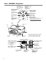
Your DP5800 Projector
The remote control will function within
16 feet of the projector sensor and
within 30° to both the left and right.
Speaker
Handle
Cooling fan
(exhaust)
Lens Cooling fan
(intake)
Remote control
sensor
Remote control
sensor
INPUT button
To select the input source.
Each time this button is pressed, the input source is
changed in sequence as shown below.
RGB1 RGB2 VIDEO1 VIDEO2
RESET button
Resets unit to factory
settings.
LAMP indicator
Glows when the lamp
should be replaced.
(See page 11.)
ON indicator
Blinks in Standby mode.
Glows in operation mode.
(See page 11.)
VIDEO input terminal
(on video-equipped models only)
S-VIDEO input terminal
Mini DIN 4pin connector
VIDEO input terminal
RCA Jack
AUDIO L/R input terminal
RCA Jack
MAIN POWER switch
Main power ON/OFF switch.
RGB input terminal
RGB input terminal
D-sub 15 pin
RGB output
terminal
RGB output terminal
D-sub 15 pin
CONTROL terminal
D-sub 15 pin RS232
AC IN socket
Connect the provided
power cord.
AUDIO input
terminal
Stereo mini jack
AUDIO output
terminal
(RGB/VIDEO)
Stereo mini jack
TEMP Indicator
Glows when temperature
inside the projector is too
high. (See page 11.)
ZOOM buttons
Adjust picture size.
MUTE button
MENU button
Picture adjustments.
Refer to pages 12 − 16
for details.
STANDBY / ON
button
Power ON/OFF button.
OFF sets the unit in
Standby mode.
FOCUS button
Adjusts focus.

7
RIGHT
STANDBY/ON
RISET
FOCUSZOOM
TIMER
BLANK
POSITION MUTE
RGB1/2VIDEO1/2
INPUT
VOL
MENU
RIGHT
RESET
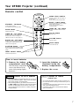
Your DP5800 Projector (continued)
Remote control
How to insert batteries
1. Remove the battery
compartment cover.
Slide the battery compartment
cover in the direction of the
arrow while pressing slightly
down on it.
2. Insert the batteries as
illustrated inside the
battery compartment.
3. Replace the cover.
Caution
Cautions on remote
control use
• Do not drop the remote control or apply any shock to it.
• Do not let the remote control get wet and do not put it on
a wet object.
• If you are not going to use the remote control for a long
time, remove the batteries from it.
• If operation of the remote control becomes difficult,
replace the batteries.
Caution
Cautions on use of batteries
• Do not use batteries not specified for this unit. Do not use
old and new batteries together. It may cause a fire, injury
due to burst of battery or liquid leakage.
• When inserting batteries, pay attention to the direction of
the
and polarity indications and insert the batteries
correctly. If the polarities are not correct, it may cause
injury or damage near the unit due to a battery explosion
or liquid leakage.
MENU STICK SWITCH
Selects or adjusts the menu items in
Menu mode.
Works as the mouse in Play mode.
RESET / RIGHT button
Resets menu items to factory settings
when menus are open.
Works as right mouse button in
Computer mode.
MENU ON / OFF button
Displays or removes the on-screen
menus.
FOCUS button
Adjusts focus.
VOLUME button
Adjusts volume.
MUTE button
Turns the Audio off.
STANDBY / ON button
Power ON/OFF button.
OFF sets the unit in Standby mode.
ZOOM button
Adjusts picture size.
TIMER ON / OFF button
Displays or removes the TIMER menu.
When a Blank screen is displayed,
TIMER can not be set. (See page 15.)
BLANK ON / OFF button
Displays a blank screen which can be
revealed by moving the MENU STICK
SWITCH. (See page 14.)
POSITION button
Move the picture with the MENU STICK
SWITCH while pressing the POSITION
button.
INPUT SELECT button
Selects the input source.

8
Screen (inches)
40
60
80
100
120
150
200
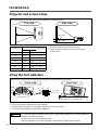
Installation
Projector and screen setup
Determine proper picture size and projection distance as illustrated below.
Using the foot adjusters
1. Lift up the projector and unlock the foot adjusters.
2. Adjust the feet to the best viewing angle, and then lock the foot adjusters.
3. To adjust the angle slightly, rotate the foot adjusters.
a (inches)
Minimum
60
89
119
149
179
224
298
Maximum
89
134
179
224
269
336
448
b (inches)
3.4
5.1
6.9
8.6
10.3
12.9
17.2
Adjust the projection position using the foot adjusters at the bottom of the projector.
Top view
b
a
Side view
Screen
Lens center
a: Distance from the projector to the screen
b: Length from the center of the lens to the bottom
of the picture
Front view
Foot adjuster
In = unlock
Out = lock
Side view
Viewing angle can be changed from 1° ~ 7°.
Caution
Do not unlock the foot adjusters unless you are supporting the projector, to avoid dropping the
projector and causing an injury.
Do not revolve the foot adjusters by force.
If the foot adjusters do not lock completely, move the foot slightly before locking.

9
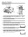
Using the Projector
Projecting the picture
1
Turn the MAIN POWER switch of the projector on. [ : ON]
•The ON indicator will glow orange.
2
Press the STANDBY/ON button.
•The ON indicator blinks (green) and then glows (green).
3
Remove the lens cap.
4
Adjust the picture size using the ZOOM buttons.
5
Adjust the focus using the FOCUS buttons.
(1) Press the FOCUS button. The on-screen display shown on the right appears.
(2) Press the Focus +/- buttons until the picture is clear.
6
Turn on all connected equipment.
See pages 17-19 for the correct sequence for turning on various equipment.
7
Press the INPUT button or the INPUT SELECT (VIDEO or RGB)
button to select the source of the projected signal.
•The selected signal input source is displayed at the bottom right of the screen.
NOTE: Video 1/2 works with video capable units only.
+++FOCUS+++
RGB 1
5
4
72
1
7
4
2
5
3
RIGHT
STANDBY/ON
RISET
FOCUSZOOM
TIMER
BLANK
POSITION MUTE
RGB1/2VIDEO1/2
INPUT
VOL
MENU
RIGHT
RESET

10
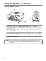
Using the Projector (continued)
Turning off the power
1
Press and hold the STANDBY/ON button for 1 second.
•The ON indicator lights up orange and the lamp turns off. About 1 minute later, the fan stops and the
indicator blinks orange.
NOTE: If you press the STANDBY/ON button for less than 1 second, the projector will not switch
to Standby mode.
2
Turn the MAIN POWER switch of the projector off. [
: OFF]
3
Replace the lens cap.
1
2
1
3
Caution
Do not turn off the projector’s MAIN POWER switch before pressing the STANDBY/ON
button. After the STANDBY/ON button is pressed, the fan will run for about 1 minute to cool
the projector.
RIGHT
STANDBY/ON
RISET
MENU
RIGHT
RESET

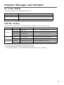
11
ON indicator
LAMP indicator
TEMP indicator
Indicator status
Lights orange
Blinks green
Lights green
Blinks orange
Lights red
Blinks red
Lights red
Blinks red
Meaning
Standby mode
Warming up
Normal operation
Cooling down
Lamp cannot light
Air filter detached
Temperature inside too high
Cooling fan failure
Action
—————————————
—————————————
—————————————
—————————————
Cool projector by power off for 20 minutes.
Check the air filter.
Check that ventilation holes are clear.
Service the projector.
Indicator display
The ON indicator, LAMP indicator and TEMP indicator will light or blink in the following cases.
The LAMP indicator will light when the lamp becomes too hot.
1. Turn off the power and let the projector cool for 20 minutes.
2. Turn the projector back on. If the LAMP indicator still glows red, contact your dealer.
Message
NO SIGNAL IS DETECTED
SYNC IS OUT OF RANGE
CHANGE THE LAMP
Action
Check the input signal connection.
The horizontal frequency of the input signal exceeds the range of the
projector,and it cannot be displayed. Change the resolution of the input signal.
The lamp should be replaced.
Projector Messages and Indicators
On screen display
The following messages may be displayed on the screen.

12
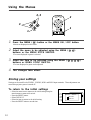
Using the Menus
Storing your settings
Settings can be saved for the VIDEO1, VIDEO2, RGB1 and RGB2 input terminals. These adjustments are
saved after projector power is turned off.
1
Press the MENU ( ) button or the MENU ON / OFF button.
•Menus are displayed on the screen.
2
Select the menu to be adjusted using the MENU ( )
buttons or the MENU STICK SWITCH.
•The menu displayed in green is selected.
3
Select the item to be adjusted using the MENU ( )
buttons or MENU STICK SWITCH.
•The item displayed in green can be adjusted.
4
The changes take effect.
To return to the initial settings
• Select the menu item to restore to the initial setting using the
menu buttons or menu stick switch.
• Press the RESET button.
• Select DEFAULT
• Select the item to restore to the initial setting.
• Press the RESET button a second time.
SETUP INPUT IMAGE OPT.
VOL
BRI
CON
SHA
COL
TIN
RESET ‘SETUP’
DEFAULT
CANCEL
2, 3
3
1
2
menu
RIGHT
STANDBY/ON
RISET
MENU
RIGHT
RESET
1

13
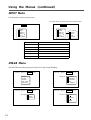
SET UP Menu
The SET UP menu lets you change the picture characteristics and position. The menus will be different for RGB
and video signals.
RGB signal Setup mumu
SETUP INPUT IMAGE OPT.
VOLUME
BRIGHT
CONTRAST
V.POSIT
H.POSIT
H.PHASE
H.SIZE
121
57
7
800
VIDEO signal Setup menu (video models only)
SETUP INPUT IMAGE OPT.
VOLUME
BRIGHT
CONTRAST
SHARPNESS
COLOR
TINT
Item
VOLUME
BRIGHT
(BRIGHTNESS)
CONTRAST
SHARPNESS*
COLOR*
TINT*
V.POSIT
(V.POSITION)
H.POSIT
(H.POSITION)
H.PHASE
H.SIZE
Range
Decrease Increase
Dark Bright
Lower Higher
Soft
Sharp
Less
More
Red
Green
Moves the picture up or down.
Moves the picture left or right.
Decreases the picture flicker.
Widens or narrows the horizontal size of picture.
NOTE: • TINT cannot be adjusted with PAL/SECAM video signal input (video models only).
• TINT, COLOR and SHARPNESS cannot be adjusted with an RGB signal input.
• V.POSIT, H.POSIT, H.PHASE and H.SIZE cannot be adjusted with a VIDEO signal input
(video models only).
Using the Menus (continued)
* Video models only

14
Using the Menus (continued)
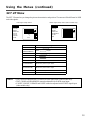
INPUT Menu
Use this menu to select an input source.
SETUP INPUT IMAGE OPT.
RGB1
RGB2
VIDEO1
VIDEO2
TEST
PATTERN
SETUP INPUT IMAGE OPT.
RGB1
RGB2
VIDEO1
VIDEO2
TEST
PATTERN
AUTO
NTSC
PAL
SECAM
SYSTEM
Item
RGB1
RGB2
VIDEO1*
VIDEO2*
TEST PATTERN
SYSTEM
Options
Selects the RGB 1 terminal.
Selects the RGB 2 terminal.
Selects the VIDEO 1 terminal.
Selects the VIDEO 2 terminal.
Selects the TEST PATTERN. (Start up screen).
Selects the video signal systems.
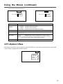
IMAGE Menu
The IMAGE menu controls picture inversion, Size, Reveal and Blanking.
SETUP INPUT IMAGE OPT.
MIRROR
BLANK
REVEAL
DISP. SIZE
MESSAGE
SETUP INPUT IMAGE OPT.
WHITE
BLUE
BLACK
BLANK
SETUP INPUT IMAGE OPT.
NORMAL
H : INVERT
V : INVERT
H&V :
INVERT
MIRROR
SETUP INPUT IMAGE OPT.
FAST
MEDIUM
SLOW
REVEAL
For Video inputs, you must also select a video format.
* Video models only.

15
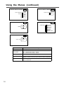
Adjustment Item
MIRROR
BLANK
REVEAL
DISP. SIZE
MESSAGE
Using the Menus (continued)
SETUP INPUT IMAGE OPT.
NORMAL
SMALL
DISP. SIZE
SETUP INPUT IMAGE OPT.
TURN ON
TURN OFF
MESSAGE
Details of adjustment
Inverts the picture horizontally or vertically for ceiling or rear screen projection.
H : INVERT Inverts the picture horizontally.
V : INTERT Inverts the picture vertically.
H&V: INVERT Inverts the picture horizontally and vertically.
Selects a color when a blank screen is displayed.
Selects the speed of revealing the image display. Use the menu stick switch to
reveal the image.
NORMAL : Displayed clock is same as signal source.
LARGE : Displayed clock is mach as signal source. (picture is wider)
NOTE: For XGA signals, NORMAL mode will compress the image, and some
lines may be missing. LARGE mode will fill the window.
Turn off the on-screen system messages. (FOCUS, selected source, etc.)
OPT. (Options) Menu
The Option menu allows you to set options for the CONTROL port. This menu can also be used to set the Break
Timer, Display Language and Automatic Shutoff.
SETUP INPUT IMAGE OPT.
COM. SPEED
COM. BITS
TIMER
LANGUAGE
AUTO OFF
Select normal or expanded image size.

16
Using the Menus (continued)
SETUP INPUT IMAGE OPT.
7N1
8N1
COM. BITS
SETUP INPUT IMAGE OPT.
10 min.
TIMER
SETUP INPUT IMAGE OPT.
ENGLISH
FRANCAIS
DEUTSCH
ESPANOL
ITALIANO
NORSK
NEDERLANDS
LANGUAGE
SETUP INPUT IMAGE OPT.
0 min.
STOP
AUTO OFF
Adjustment Item
COM. SPEED
COM. BITS
TIMER
LANGUAGE
AUTO OFF
Details of adjustment
Select speed of data transmission.
Select the data format.
7N1... 7 data-bits, No parity, 1 stop bit.
8N1... 8 data-bits, No parity, 1 stop bit.
Sets the on-screen timer.
Selects a language for the on-screen menu.
(English, Francais, Deutsch, Espanol, Italiano, Norsk, Nederlands)
Set the amount of time before the power will turn off if the input
source is turned off.
SETUP INPUT IMAGE OPT.
1200
2400
4800
9600
19200
COM. SPEED
(bps)

17
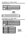
Connecting to a Video Source
1.Input signal specifications
S-VIDEO signal
VIDEO signal
AUDIO signal
Input
Output
2.Signal input terminal pin-out
Connecting to an RGB Signal
1.Input / output signal specifications
Video signal
Horizontal sync signal
Vertical sync signal
Composite sync signal
Audio signal
Input
Output
Analog 0.7Vp-p 75 Ω termination (Positive polarity)
TTL level (Positive/negative polarity)
TTL level (Positive/negative polarity)
TTL level
200mVrms, 20k Ω below (MAX 3.0Vp-p)
0 ∼ 200mVrms, 1k Ω
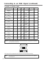
2.Signal input / output terminal pin-out
1
2
3
4
5
6
7
8
Video signal (Red)
Video signal (Green)
Video signal (Blue)
N.C
N.C
Ground (for R)
Ground (for G)
Ground (for B)
Luminance signal 1.0Vp-p, 75 Ω termination
Chrominance signal 0.286Vp-p (burst signal), 75 Ω termination
1.0Vp-p, 75 Ω termination
200mVrms, 20 kΩ below (MAX 3.0Vp-p)
0~200mVrms, 1k Ω
9
10
11
12
13
14
15
N.C
Ground
Ground
N.C
Horizontal/Composite sync signal
Vertical sync signal
N.C
NOTE: Video input signal terminals have priority in the following order:
1. S-VIDEO input terminal 2. RCA jack input terminal
Chrominance signal
Ground
S VIDEO input (Mini DIN4 pin)
Luminance signal
Ground
D-sub 15 pin terminal (Female)
Available for video models only.

18
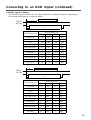
Connecting to an RGB Signal (continued)
3.Example of computer signal
Computer/Signal source
15kHz RGB
(NTSC)
VGA-1
(IBM compatible)
VGA-2
(IBM compatible)
VGA-3
(IBM compatible)
Macintosh 13 inch mode
(Apple)
VESA (72 Hz)
SVGA
(VESA 60Hz)
SVGA
(VESA 72Hz)
Macintosh 16 inch mode
(Apple)
XGA
(VESA 60Hz)
XGA
(VESA 75Hz)
Resolution
H × V
—
640 × 350
640 × 400
640 × 480
640 × 480
640 × 480
800 × 600
800 × 600
832 × 624
1024 × 768
1024 × 768
fH
(kHz)
15.7
31.5
31.5
31.5
35.0
37.9
37.9
48.1
49.7
48.4
60.0
fV
(Hz)
60
70.1
70.1
59.9
66.7
72.8
60.3
72.2
74.5
60.0
75.0
Sync Signal
H, V composite
H, V separate
H: Positive
V: Negative
H, V separate
H: Negative
V: Positive
H, V separate
H: Negative
V: Negative
H, V separate
H: Negative
V: Negative
H, V separate
H: Negative
V: Negative
H, V separate
H: Positive
V: Positive
H, V separate
H: Positive
V: Positive
H, V separate
H: Positive
V: Positive
H, V separate
H: Negative
V: Negative
H, V separate
H: Positive
V: Positive
Note
∗
1
SW 1 ON
SW 2 ON
∗
1
SW 2 ON
SW 4 ON
Interlaced /
Non-interlaced
Interlaced
Non-interlaced
Non-interlaced
Non-interlaced
Non-interlaced
Non-interlaced
Non-interlaced
Non-interlaced
Non-interlaced
Non-interlaced
Non-interlaced
NOTE: A MAC adapter is necessary to set the resolution mode. The projector is compatible
with 13inch and 16inch mode.
654321
OFFON
Sample 16inch mode adaptor
NOTE: Some input sources may not be displayed properly because they are not compatible
with the projector.
XGA images will be compressed to 800 x 600. Some lines may therefore be missing.

19
Connecting to an RGB Signal (continued)
4.Initial signal settings
The following signals are initially set. The settings may need to be changed for specific computer types.
Use the Setup menu (page 16) to adjust the settings.
DATA
HSYNC
a
c
d
b
a
9.8
5.7
5.7
5.7
5.3
5.4
5.4
3.7
5.0
4.0
3.6
c
4.7
3.8
3.8
3.8
2.1
1.3
3.2
2.4
1.1
2.8
1.2
b
52.7
25.2
25.2
25.2
21.2
20.5
20.0
16.0
14.5
16.0
12.8
d
63.6
31.8
31.8
31.8
28.6
26.7
26.4
20.8
20.1
20.4
16.6
Computer/Signal sorce
Horizontal Timing (µs)
15kHz RGB
VGA-1
VGA-2
VGA-3
Mac 13inch mode
VESA (72Hz)
SVGA (60Hz)
SVGA (72Hz)
Mac 16inch mode
XGA (60Hz)
XGA (75Hz)
DATA
VSYNC
a
c
d
b
a
19.5
62
37
35
42
31
27
29
42
48
44
c
3
2
2
2
3
3
4
6
4
8
3
b
240
350
400
480
480
480
600
600
624
768
768
d
262.5
449
449
525
525
520
628
666
667
817
803
Computer/Signal sorce
Vertical Timing (µs)
15kHz RGB
VGA-1
VGA-2
VGA-3
Mac 13inch mode
VESA (72Hz)
SVGA (60Hz)
SVGA (72Hz)
Mac 16inch mode
XGA (60Hz)
XGA (75Hz)

20
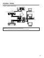
Caution
Turn off the power of both the projector and computer before connecting to the CONTROL port.
Connect the computer to the CONTROL terminal of the projector using an appropriate cable.
Refer to the instruction manual for each device before connecting them through the CONTROL port.
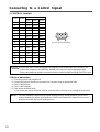
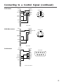
Connecting to a Control Signal
1.CONTROL terminal
Pin No
.
1
2
3
4
5
6
7
8
9
10
11
12
13
14
15
RS232C
GND
RDP
TDP
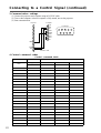
2.Mouse emulation
(1) Turn the projector and computer off.
(2) Connect the projector and the mouse terminal of computer using an appropriate cable.
(3) Turn on the projector.
(4) Turn on the computer.
(5) Start mouse emulation mode.
If you cannot start mouse emulation, reset the computer with a soft reset or by pressing the reset switch.
NOTE: For some Notebook computers with internal pointing devices, mouse emulation will not work
without disabling the internal pointing device. Check your Notebook PC manual for the correct
procedure to disable the internal pointing device.
D-sub 15 pin terminal (Male)
PS/2
CLK
DATA
SEL0
SEL1
GND
+5V
Mouse
ADB
SDATA
SEL0
SEL1
GND
+5V
Serial
TDM
SEL0
SEL1
READY
GND
Page is loading ...
Page is loading ...
Page is loading ...
Page is loading ...
Page is loading ...
Page is loading ...
Page is loading ...
Page is loading ...
Page is loading ...
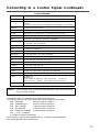
-
 1
1
-
 2
2
-
 3
3
-
 4
4
-
 5
5
-
 6
6
-
 7
7
-
 8
8
-
 9
9
-
 10
10
-
 11
11
-
 12
12
-
 13
13
-
 14
14
-
 15
15
-
 16
16
-
 17
17
-
 18
18
-
 19
19
-
 20
20
-
 21
21
-
 22
22
-
 23
23
-
 24
24
-
 25
25
-
 26
26
-
 27
27
-
 28
28
-
 29
29


Proxima DP5800 User manual
- Category
- Data projectors
- Type
- User manual
- This manual is also suitable for
Ask a question and I''ll find the answer in the document
Finding information in a document is now easier with AI
Related papers
-
Infocus Desktop Projector 6860 User manual
-
 Proxima Desktop Projector 6860 User manual
-
Proxima Lightbook User manual
-
Proxima DP5100 User manual
-
 Proxima DP2400 User manual
-
 Proxima Desktop Projector 5500 User manual
-
 Proxima PL-300 User manual
-
Ask Proxima DP9100 User manual
-
 Proxima DESKTOP PROJECTOR 4200 User manual
-
 Proxima DESKTOP PROJECTOR 4200 User manual


Other documents
-
BOXLIGHT CP-S830W/E User manual
-
Panasonic PT-D10000U User manual
-
Panasonic PTD5500EL User manual
-
-
Liesegang ddv 1800 User manual
-
Panasonic PT-D3500E User manual
-
3M MP8640 User manual
-
-
-