GENERAL INFORMATION
All of the parts on the plan are identified by a number or a letter.
Parts identified by a number are laser cut parts.
Parts identified by a letter are stripwood pieces that you cut and fit on assembly.
The slight discoloration of the edges of the laser cut parts may be removed by lightly sanding them with 400 grit
sandpaper.
The assembly of this model begins by building the fuselage side frames and then parts are added or assembled in
numerical order.
Your kit contains the following parts. Please check your kit for any missing or damaged parts before starting construction.
COMPLETE KIT PARTS LIST
1 Plan Sheet #1 1 Plan Sheet #2 1 Decal Sheet
3 Yellow Tissue 1 1/16"x12" Music Wire 1 Tail Wheel Assembly
1 15" Thread 2 1/ 8"x4" Solder 3 3 1/4"x6" Window Material
8 1/16"sq.x18" Balsa Strip 12 3/32"sq.x18" Balsa Strip 2 1/8"sq.x18" Balsa Strip
1 3/16"x1 3/4" Dowel 1 Instruction Manual 1 9" Plastic Propeller
1 Propeller Shaft 2 Brass Thrust Washers 1 Plastic Propeller Bearing
2 1/4"x1/2" Black Rubber Tube 2 1/16"x1/16" Plastic Tube 1 6" Copper Wire
1 3/16"x60" Rubber Strip 15 Laser Cut Sheets
Tools and Building Supplies
You will need the following items to assemble this model. You must read and follow all of the manufactures
instructions provided with these items!
-Glue CA, White Glue, Sigment or Ambroid all work well.
-Cutting Tools A single edge razor blade can be used for all of the cutting.
-Clear Dope, Thinner & paint brush -200, 320 and 400 sandpaper
-Straight Pins -Wax Paper
-Needle nose pliers -Crayon or Candle
-1/4" Drill Bit -Building Board

.
The first thing that you need to do is to identify and mark the part numbers on the laser cut parts using the drawings on the
following pages as a guide.
It is possible that several of the laser cut parts may not be completely cut through. If this is the case you can free the part from
the sheet quickly using an X-acto knife.
NOTE: The slight discoloration on the edges of the laser cut parts may be removed by lightly sanding the edges with 400 grit
sandpaper.

.

.
Building the Fuselage
1.
Cover the fuselage side frame plan with wax paper. Build the two fuselage side frames over the plan. Glue a piece of 3/32"
sq. balsa across the bottom front of formers #8 and #10.
2.
Place former #8 into position on one fuselage side. Glue it to the bottom and middle longeron on the fuselage side frame.
Do not glue #8 to #2 at this time. Glue #9 into position as shown. The front face of #9 should be flush with the front of the
3/32" sq. uprights on the fuselage side.
3.
Place the opposite fuselage side into position. Carefully check the fuselage for squareness and then glue #8 and #9 to the
second fuselage side.
4.
Glue #10 into position to the fuselage longerons in four places and also glue to #2. Sand the taper in the tailpost and rear
fuselage sides as shown on the plan. Pull the rear fuselage together and align the tailposts. Check the fuselage alignment
and glue the tailposts together.
5.
Glue #11 into the bottom of the fuselage in front of the tailpost. Glue the fuselage cross pieces (#12 through #18) into
position in numerical order. Glue #19 and #20 into position. Glue the four diagonal 3/32" sq. balsa pieces to the rear
fuselage as shown on the plan.
6.
Glue #21 through #25 into position.
7.
Glue formers #26 through #31 to the top rear fuselage in the positions shown on the plan.
8.
Assemble the front and rear spar boxes. The rear spar box is made from #32, #33 and #34. The front spar box is made
from #35, #36 and #37.
9.
Glue the spar boxes into position. Glue #8 to #2. Glue #38, the two #39s and the two #40s into position.
10.
Glue the two #41s into position on the outside of the two #4s.
11.
Glue two 1/16" sq. balsa stringers to each side of the fuselage between #8 and the tailpost.
12.
Glue three 1/16" sq. balsa stringers to the top rear fuselage. The center stringer runs from #32 in the front and rests on top
of the tailpost. The top corner stringers run from #10 to the sides of the tailpost directly below the center stringer.
13.
Glue the five 1/16" sq. nose stringers into position.
14.
Glue #42 and #43 to #44. Maintain a 1/16" gap between #42 and #43.
15.
Bent the landing gear to shape and glue it between #42 and #43. Now glue the landing gear assembly to the front of #9.
16.
Glue one #45, a 3/32" sq. balsa diagonal and one #46 to each fuselage side.
17.
Glue the wheel parts together. Sand the wheels to shape. The wheels will not be permanently mounted on the model until
after it is covered. Do not glue the #55 hub caps in place at this time.
18.
Glue the diagonal 3/32" sq. windshield braces in place.
19.
Glue the nose block pieces together as shown on the plan. Using the hole in #47 as a guide, drill the 1/4" hole through the
nose block making sure to add the proper right and down thrust.
20.
Glue the two #50's to the rear of the fuselage maintaining an even 3/32" gap between #50 and #5 on each side. This gap
form the slot that the stabilizer will be glued into after the model is covered.
21.
Sand the fuselage smooth all over. Sand the nose block to shape. The nose block should be a snug fit on the front of the
model and should be removable (do not glue to model).
22.
Cut the two leading edge farings from the plan and glue into positionbetween #2 and #40 on each side of the fuselage. Now
trim and sand smooth. Now glue the nose paper into position.
23.
Glue #65 and #66 together and sand to shape. Do not glue to the model until after covering.

.
Building the Tail Surfaces
24.
Cover the Rudder plan with wax paper. Pin #67 into position on the plan. Now pin and glue #68 and #69 into place. Now
complete the fin by adding the two 3/32" sq. balsa pieces. Remove the fin from the plan.
25.
Cut the rudder laminating pattern from the plan and glue it to a piece of cardboard. Trim the cardboard to the size of the
paper form.
26.
Coat the edges of the form with wax by rubbing the edges with a crayon or candle. Now pin the form to your wax paper
covered building board.
27.
Carefully cut one set of the laser cut laminating strips (#72) from the sheet. Cut one end off so that you have a strip of three
smaller strips that remain attached to each other at one end. Spray this strip with an ammonia based glass cleaner and
allow it to soak for about one minute.
28.
Wipe the laminating strip dry by pulling it through a paper towel several times. Place the attached end next to the form and
pin in place at one end of the form. Nowwrap the laminating strip around the form and pin the opposite end into place. The
laminating strip should be tight against the form between the trim lines.
29.
Now brush a small amount of white glue (thinned 50-50 with water)onto the laminating strip and allow to dry.
30.
Pin #71 to the plan. Pin and glue #72 into position.
31.
When the glue is dry on the laminating strip, cut the laminating strip at the front trim line and position on plan. Mark and trim
excess at opposite end.
32.
Glue the laminated trailing edge into position. Add the remaining 3/32" sq. balsa pieces to the rudder. When the rudder is
dry, remove it from the plan.
33.
Build the two elevators and the stabilizer as you did the fin and rudder.
34.
Sand all of the edges of the fin, rudder, stabilizer and elevators round except the bottom of #67 where it will contact the
fuselage.
Building the Wings
35.
Cover the right wing plan with wax paper. Glue one #76 to one #77 and glue one #78 to one #79.
36.
Pin the front spar (#76 and #77) into position on the plan. The spar will be slightly long at the tip. This is to allow the tip to be
trimmed to length on assembly. Pin the rear spar (#78 and #79) into position on the plan. Pin the trailing edge #80 into
position on the plan.
37.
Glue rib #81 into position on the spars and trailing edge. Use the dihedral gauge #81-A to make sure that the top of this rib
is angled toward the wing tip by the proper angle. Now glue the remaining ribs # 82, #83 and #84 into position 90 degrees
to the building board.
38.
Glue the 1/8" sq. balsa leading edge into position. The outboard end butts against the inboard face of rib #83.
39.
Laminate the wing tip as you did the tail surfaces. Trim on the front trim line and glue to the front of #83 and the leading
edge.
40.
Pull the wingtip back to match the plan, allowing it to pull under the spars slightly. Pin the tip in place against #80. Trim the
spars to the inside of the wing tip. Pull the wing tip up and glue it centered on the spars. Glue the remaining end to #80.
Now trim the excess at the trailing edge.
41.
Glue the leading edge sheet #85 into position. Trim the outboard piece to fit the wing tip before gluing into position. You
may slightly moisten the outside surface of #80 to allow it to bend easier.
42.
When the wing is completely dry, remove it from the plan and sand smooth. Sand the leading edge round and taper the
trailing edge to the shape shown on the plan.
43.
Now repeat the previous steps to build the left wing.

.
Covering the Model
44.
Sand all of the parts smooth. Test fit the wings to the fuselage. Test fit the tail surfaces with the fuselage. Make any
adjustments necessary to achieve the proper fit. Cut the windshield using the pattern on the plan and check the fit With the
fuselage.
45.
Cover the model, applying the tissue With clear dope. When the parts are covered, shrink the tissue by lightly misting it with
water or rubbing alcohol.
46.
Apply two coats of clear dope thinned 50
-
50 to the entire model.
47.
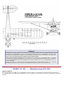
Apply the decals using the 3
-
view as a guide for placement.
Final Assembly
48.
Make one dummy engine cylinder by stacking parts #56 -
#62 on a 1" length of 3/32" sq. balsa stick. Trim the 3/32" sq. flush
With #62. Glue #63 into position.
49.
Repeat to assemble the other three cylinders.
50.
Paint the cylinders With black dope.
51.
Glue the cylinders to the nose of the fuselage. Cut the paper cooling shrouds from the plan. Bend them and glue them to
the nose of the model. Now paint the cooling shrouds with black dope.
52.
The landing gear farings #64 should be covered with tissue and doped. Sand the upper edge to fit the fuselage and glue
#46 into position on each side. Wrap tissue around the front of #64 to cover the landing gear wire and dope in place.
53.
Paint the wheels black. Slide the wheels onto the axles. Mark and trim the axles to length. Secure the wheels to the axle
with a small piece of plastic tube glued to the axle.
54.
Cover the hub caps #55 with tissue. Apply the CUB decal and carefully glue them to the wheels.
55.
Additional scale details can be added to the landing gear if desired. These are shown on the plan. These details should be
made removable to prevent damage during flight.
56.
Glue the tail wheel assembly to the model.
57.
Glue the windshield to the model. Cut the side windows from plastic and test fit then glue into position.
58.
Draw the scale door outline on the fuselage. Draw the ailerons onto the wings. A technical pen works best for this.
59.
Mark the hinge points on the tail surfaces.
60.
Slide the stabilizer into the slot in the fuselage and center it. Carefully check the stabilizer for alignment and glue into
position.
61.
Cut several short lengths of the copper wire and glue them in place hinging the elevators to the stabilizer.
62.
Fit and glue the fin to the fuselage. Make sure that the fin is perpendicular to the stabilizer. Now hinge the rudder to the fin
and fuselage.
63.
Glue thread into position to simulate the tail bracing wires.
64.
Glue the wings to the fuselage using the dihedral gauge #88 to establish the correct angle.
65.
Assemble the wing struts over the plan. Sand the edges of the struts round and cover them with tissue and dope.
66.
Carefully trim the ends of the struts to length so that the struts fit in the proper positions. Now glue the struts into position.
67.
Make the jury struts from 1/16" sq, balsa strips that have been covered with tissue.

.
68.
Assemble the propeller and tie the rubber motor. Install the prop and motor, using the 3/32" dowel to retain the motor at the
aft end of the model.
69.
Attempt to balance the model at the position shown on the plan. If the model is tail heavy (it probably is), Make the dummy
exhaust from the 1/8" dia. solder provided in the kit. Glue the exhaust to the model. In the event that your model balances
properly or is nose heavy, make the exhaust from scrap balsa from one of the laser cut sheets, glue into position and paint
it silver.
70.
Do a final balance of your model and add weight (modeling clay) to the nose or tail as required to balance the model at the
position shown on the plan.
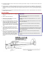
Your First Flights
1.
Make sure that all flying surfaces are straight and
warp free.
Safety Rules
1.
Fly your model in a large open area that is free of obstructions,
people or their property.
2.
Do not fly your model in the vicinity of power lines, trees, streets or
buildings.
3.
Never try to retrieve any model stuck in power lines, in trees or on a
roof or other high place.
4.
Position yourself at least 150' from spectators before launching
model.
5.
Never launch model directly at another person or other object.
6.
Never stick your fingers into a spinning propeller. Do not try to stop a
spinning propeller with your hand or fingers. Never stick any object
into a spinning propeller.
7.
Fly your model only on calm days. Do not fly when the wind is
blowing.
8.
Get proper permission before retrieving your model from private
property.
2.
Wind the motor about 100 turns.
3.
Point the nose of the model into any gentle
breeze that may be blowing.
4.
Release the propeller and after it starts turning
gently toss the model aiming the nose at a point
on the ground 100' in front of you. Adjust the
model to circle while increasing the number of
turns in the motor. Adjustments can be made by
gently bending the tail surfaces and wing trailing
edge.
5.
A properly trimmed model will circle to the left
while climbing under power, level out as the
power runs down and transition into a right hand
gliding circle.
6.
When your model is flying well consistently, lock
the tail surfaces into position by applying several
small drops of white glue on the hinge line. In the
future if the tail surfaces need to be readjusted
you can soften the white glue by brushing on a
small amount of warm water and waiting a few
minutes.

.
WARRANTY
Herr Engineering Corp. guarantees this kit to be free from defects in both materials and workmanship at the time
of purchase. This warranty does not cover any component damaged buy use or modification. In no case shall
Herr Engineering Corporation's liability exceed the original cost of the purchased kit. Further Herr Engineering
Corp. reserves the right to change or modify this warranty without notice.
In that Herr Engineering Corporation has no control over the assembly or use, no liability shall be assumed or
accepted for any damage resulting from the use by the user during construction of the kit or the use of the final
user assembled product. By the act of building this kit and/or using the final user assembled product, the user
accepts all liability.
If the buyer and/or user is not prepared to accept all of the liability associated with this product, he is advised to
immediately return this kit in new and unused condition to the place of purchase for a full refund.
©
Copyright SIG Mfg. Co., Inc.
SIG MFG. CO., INC............Montezuma, Iowa 50171
-
0520
LIMIT OF LIABILITY:
In use of our products, Sig Mfg. Co.'s only obligation shall be to replace such quantity of the product proven to be defective.
User shall determine the suitability of the product for his or her intended use and shall assume all risk and liability in connection
therewith.
-
 1
1
-
 2
2
-
 3
3
-
 4
4
-
 5
5
-
 6
6
-
 7
7
-
 8
8