ViewSonic CDP4260-TL User guide
- Category
- Public displays
- Type
- User guide

CDP4260-TL/CDP5560-TL
LCD Monitor
User Guide
Model No. VS15795/VS15796
IMPORTANT: Please read this User Guide to obtain important information on installing
and using your product in a safe manner, as well as registering your product for future
service. Warranty information contained in this User Guide will describe your limited
coverage from ViewSonic Corporation, which is also found on our web site at http://
ZZZYLHZVRQLFFRPLQ(QJOLVKRULQVSHFL¿FODQJXDJHVXVLQJWKH5HJLRQDOVHOHFWLRQ
box in the upper right corner of our website. “Antes de operar su equipo lea cu
idadosamente las instrucciones en este manual”

i
Compliance Information
NOTE: This section addresses all connected requirements and statements regarding regulations.
Confirmed corresponding applications shall refer to nameplate labels and relevant markings on
unit.
FCC Statement
This device complies with Part 15 of the FCC Rules. Operation is subject to the following two
conditions: (1) this device may not cause harmful interference, and (2) this device must accept any
interference received, including interference that may cause undesired operation.
NOTE: This equipment has been tested and found to comply with the limits for a Class A/
Class B digital device, pursuant to Part 15 of the FCC Rules. These limits are designed to
provide reasonable protection against harmful interference when the equipment is operated in a
commercial environment. This equipment generates, uses, and can radiate radio frequency energy
and, if not installed and used in accordance with the instructions, may cause harmful interference
to radio communications. Operation of this equipment in a residential area is likely to cause harmful
interference in which case the user will be required to correct the interference at his/her own
expense.
• Reorient or relocate the receiving antenna.
• Increase the separation between the equipment and receiver.
• Connect the equipment into an outlet on a circuit different from that to which the receiver is
connected.
• Consult the dealer or an experienced radio/TV technician for help.
Warning: To comply with the limits for the Class A/Class B digital device, pursuant to Part 15 of
the FCC Rules, this device must be installed in computer equipment certified to comply with the
Class A/Class B limits. All cables used to connect the computer and peripherals must be shielded
and grounded. Operation with non-certified computers or non-shielded cables may result in
interference to radio or television reception. Changes and modifications not expressly approved by
the manufacturer could void the user’s authority to operate this equipment.
For Canada
CAN ICES-3 (A/B)/NMB-3(A/B)

ii
CE Conformity for European Countries
The device complies with the EMC Directive 2004/108/EC and Low Voltage Directive
2006/95/EC.
Following information is only for EU-member states:
The mark shown to the right is in compliance with the Waste Electrical and Electronic
Equipment Directive 2012/19/EC (WEEE).
The mark indicates the requirement NOT to dispose of the equipment as unsorted
municipal waste, but use the return and collection systems according to local law.
If the batteries, accumulators and button cells included with this equipment, display the
chemical symbol Hg, Cd, or Pb, then it means that the battery has a heavy metal content
of more than 0.0005% Mercury or more than, 0.002% Cadmium, or more than 0.004%
Lead.
Industry Canada Notice
This device complies with Canadian RSS-210.To prevent radio interference to the licensed service,
this device is intended to be operated indoors and away from windows to provide maximum
shielding. Equipment (or its transmitting antenna) that is installed outdoors is subject to licensing.
The installer of this radio equipment must ensure that the antenna is located or pointed such that it
does not emit RF field in excess of Health Canada limits for the general population; consult Safety
Code 6, obtainable from Health Canada’s website www.hc-sc.gc.ca/rpb.
R&TTE Compliance Statement
This device complies with the Essential Requirements of the R&TTE Directive of the European
Union (1999/5/EC). This equipment meets the following conformance standards:
ETSI EN 300 328
EN 301 489-01
EN 301 489-17
EN 62311
Notified Countries: Germany, UK, Netherlands, Belgium, Sweden, Denmark,
Finland, France, Italy, Spain, Austria, Ireland, Portugal, Greece, Luxembourg,
Estonia, Latvia, Lithuania, Czech Republic, Slovakia, Slovenia, Hungary, Poland and Malta.

iii
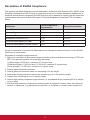
Declaration of RoHS2 Compliance
This product has been designed and manufactured in compliance with Directive 2011/65/EU of the
European Parliament and the Council on restriction of the use of certain hazardous substances in
electrical and electronic equipment (RoHS2 Directive) and is deemed to comply with the maximum
concentration values issued by the European Technical Adaptation Committee (TAC) as shown
below:
Substance
Proposed Maximum
Concentration
Actual Concentration
Lead (Pb) 0,1% < 0,1%
Mercury (Hg) 0,1% < 0,1%
Cadmium (Cd) 0,01% < 0,01%
Hexavalent Chromium (Cr
6+
) 0,1% < 0,1%
Polybrominated biphenyls (PBB) 0,1% < 0,1%
Polybrominated diphenyl ethers (PBDE) 0,1% < 0,1%
Certain components of products as stated above are exempted under the Annex III of the RoHS2
Directives as noted below:
Examples of exempted components are:
1. 0HUFXU\LQFROGFDWKRGHÀXRUHVFHQWODPSVDQGH[WHUQDOHOHFWURGHÀXRUHVFHQWODPSV&&)/DQG
EEFL) for special purposes not exceeding (per lamp):
(1) Short length ( 500 mm): maximum 3.5 mg per lamp.
(2) Medium length ( 500 mm and 1,500 mm): maximum 5 mg per lamp.
(3) Long length ( 1,500 mm): maximum 13 mg per lamp.
2. Lead in glass of cathode ray tubes.
3. /HDGLQJODVVRIÀXRUHVFHQWWXEHVQRWH[FHHGLQJE\ZHLJKW
4. Lead as an alloying element in aluminium containing up to 0.4% lead by weight.
5. Copper alloy containing up to 4% lead by weight.
6. Lead in high melting temperature type solders (i.e. lead-based alloys containing 85% by weight
or more lead).
7. Electrical and electronic components containing lead in a glass or ceramic other than dielectric
ceramic in capacitors, e.g. piezoelectronic devices, or in a glass or ceramic matrix compound.

iv
Safety Precautions
FOR OPTIMUM PERFORMANCE, PLEASE NOTE THE FOLLOWING WHEN SETTING UP AND
USING THE LCD COLOR MONITOR:
• DO NOT REMOVE MONITOR BACK COVER. There are no user serviceable parts inside and
opening or removing covers may expose you to dangerous shock hazards or other risks. Refer
DOOVHUYLFLQJWRTXDOL¿HGVHUYLFHSHUVRQQHO
• Do not spill any liquids into the cabinet or use your monitor near water.
• Do not insert objects of any kind into the cabinet slots, as they may touch dangerous voltage
SRLQWVZKLFKFDQEHKDUPIXORUIDWDORUPD\FDXVHHOHFWULFVKRFN¿UHRUHTXLSPHQWIDLOXUH
• Do not place any heavy objects on the power cord. Damage to the cord may cause shock or
¿UH
• Do not place this product on a sloping or unstable cart, stand or table, as the monitor may fall,
causing serious damage to the monitor.
• Do not place any objects onto the monitor and do not use the monitor outdoors.
• 7KHLQVLGHRIWKHÀXRUHVFHQWWXEHORFDWHGZLWKLQWKH/&'PRQLWRUFRQWDLQVPHUFXU\3OHDVH
follow the laws or rules of your municipality to dispose of the tube properly.
• Do not bend power cord.
• Do not use monitor in high temperature, humid, dusty, or oily areas.
• If monitor or glass is broken, do not come in contact with the liquid crystal and handle with
care.
• Allow adequate ventilation around the monitor, so that heat can properly dissipate. Do not
block ventilated openings or place the monitor near a radiator or other heat sources. Do not
put anything on top of the monitor.
• The power cable connector is the primary means of detaching the system from the power
supply. The monitor should be installed close to a power outlet, which is easily accessible.
• Handle with care when transporting. Save packaging for transporting.
• Please clean the holes of back cabinet to reject dirt and dust at least once a year because of
set reliability.
• If using the cooling fan continuously, it’s recommended to wipe holes a minimum of once a
month.
• When installing the remote control batteries;
- Align the batteries according to the (+) and (-) indications inside the case.
$OLJQWKHLQGLFDWLRQRIWKHEDWWHU\¿UVWLQVLGHWKHFDVH

v
CAUTION:
Immediately unplug your monitor from the wall outlet and refer servicing to qualified service
personnel under the following conditions:
• When the power supply cord or plug is damaged.
• If liquid has been spilled, or objects have fallen into the monitor.
• If the monitor has been exposed to rain or water.
• If the monitor has been dropped or the cabinet damaged.
• If the monitor does not operate normally by following operating instructions.
Recommended Use
CAUTION:
• For optimum performance, allow 20 minutes for warm-up.
• Rest your eyes periodically by focusing on an object at least 5 feet away. Blink often.
• Position the monitor at a 90° angle to windows and other light sources to minimize glare and
UHÀHFWLRQV
• Clean the LCD monitor surface with a lint-free, nonabrasive cloth. Avoid using any cleaning
solution or glass cleaner!
• Adjust the monitor’s brightness, contrast and sharpness controls to enhance readability.
• $YRLGGLVSOD\LQJ¿[HGSDWWHUQVRQWKHPRQLWRUIRUORQJSHULRGVRIWLPHWRDYRLGLPDJH
persistence (after image effects).
• Get regular eye checkups.
Ergonomics
To realize the maximum ergonomic benefits, we recommend the following:
• Use the preset Size and Position controls with standard signals.
• Use the preset Color Setting.
• Use non-interlaced signals.
• 'RQRWXVHSULPDU\FRORUEOXHRQDGDUNEDFNJURXQGDVLWLVGLI¿FXOWWRVHHDQGPD\SURGXFH
H\HIDWLJXHGXHWRLQVXI¿FLHQWFRQWUDVW

vi
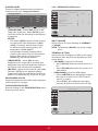
Table Of Contents
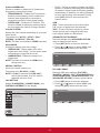
4. OSD Menu ............................................ 13
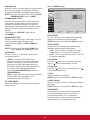
4.1. Navigating the OSD Menu .......... 13
4.1.1. Navigating the OSD menu
using the remote control .... 13
4.1.2. Navigating the OSD menu
using the display’s control
buttons ............................... 13
4.2. OSD Menu Overview ................... 13
4.2.1. PICTURE menu ................. 13
4.2.2. SCREEN menu .................. 14
4.2.3. AUDIO menu ...................... 15
4.2.4. PIP menu ........................... 16
4.2.5. CONFIGURATION1 menu . 16
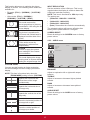
4.2.6. CONFIGURATION2 menu . 18
4.2.7. CONFIGURATION3 menu . 19
4.2.8. ADVANCED OPTION
menu .................................. 20
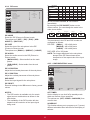
5. Commercial Display LAN Control ..... 22
5.1. OSD Menu Setup for Network
Connection ................................... 22
5.2. Before Using Web Browser
Control .......................................... 22
5.3. Access from Web Browser ........... 22
6. Input Mode ........................................... 25
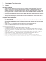
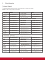
7. Cleaning and Troubleshooting .......... 26
7.1. Cleaning ....................................... 26
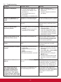
7.2. Troubleshooting ............................ 27
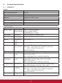
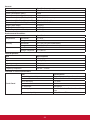
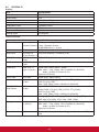
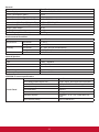
7HFKQLFDO6SHFL¿FDWLRQV .................... 28
8.1. CDP4260-TL ................................ 28
8.2. CDP5560-TL ................................ 30
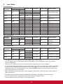
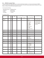
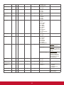
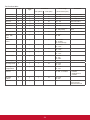
8.3. RS232 Command Table ............... 32
9. Other Information ............................... 35
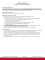
Customer Support................................. 35
Limited Warranty .................................. 36
Mexico Limited Warranty ...................... 38
1. Unpacking and Installation ...................1
1.1. Unpacking .......................................1
1.2. Package Contents ...........................1
1.3. Installation Notes .............................1
1.4. Installing and Removing Table
Stands (optional) .............................2
1.5. Installing and Removing OPS
module (CDP4260-TL/
CDP5560-TL series) (optional) ........3
1.6. Mounting on a Wall ..........................3
1.6.1. VESA Grid .............................4
2. Parts and Functions ..............................5
2.1. Control Panel ..................................5
2.2. Input/Output Terminals ....................6
2.3. Remote Control ...............................7
2.3.1. General functions ..................7
2.3.2. Inserting the batteries in
the remote control .................8
2.3.3. Handling the remote control ..8
2.3.4. Operating range of the
remote control .......................8
3. Connecting External Equipment ..........9
3.1. Connecting External Equipment
(DVD/VCR/VCD) .............................9
3.1.1. Using COMPONENT video
input ......................................9
3.1.2. Using HDMI video input ........9
3.2. Connecting a PC .......................... 10
3.2.1. Using VGA input ................. 10
3.2.2. Using DVI input .................. 10
3.2.3. Using HDMI input ............... 10
3.3. Connecting Audio Equipment ....... 11
3.3.1. Connecting external
speakers ............................ 11
3.3.2. Connecting an external
audio device ....................... 11
3.4. Connecting Multiple Displays in
D'DLV\FKDLQ&RQ¿JXUDWLRQ ......... 12
3.4.1. Display control connection . 12
3.4.2. Digital video connection ..... 12
3.4.3. Analog video connection .... 12

vii
Copyright Information
Copyright © ViewSonic Corporation, 2014. All rights reserved.
ViewSonic
©
and the three birds logo are registered trademarks of ViewSonic Corporation.
ENERGY STAR
®
is a registered trademark of the U.S. Environmental Protection Agency (EPA).
As an ENERGY STAR
®
partner, ViewSonic Corporation has determined that this product meetsthe
ENERGY STAR
®
guidelines for energy efficiency.
Disclaimer: ViewSonic Corporation shall not be liable for technical or editorial errors or omissions
contained herein; nor for incidental or consequential damages resulting from furnishing this
material, or the performance or use of this product.
In the interest of continuing product improvement, ViewSonic Corporation reserves the right to
change product specifications without notice. Information in this document may change without
notice.
No part of this document may be copied, reproduced, or transmitted by any means, for any purpose
without prior written permission from ViewSonic Corporation.
Product Registration
To meet your future needs, and to receive any additional product information as it becomes
available, please register your product on the Internet at: www.viewsonic.com.
The ViewSonic
®
Wizard CD-ROM also provides an opportunity for you to print the registration form,
which you may mail or fax to ViewSonic.
For Your Records
Product Name:
Model Number:
Document Number:
Serial Number:
Purchase Date:
CDP4260-TL/CDP5560-TL
ViewSonic LCD Monitor
VS15795/VS15796
CDP4260-TL/CDP5560-TL_UG_ENG Rev. 1A 04-22-14
Product disposal at end of product life
ViewSonic respects the environment and is committed to working and living green. Thank you for
being part of Smarter, Greener Computing.
Please visit ViewSonic website to learn more.
USA & Canada: http://www.viewsonic.com/company/green/recycle-program/
Europe: http://www.viewsoniceurope.com/uk/support/recycling-information/
Taiwan: http://recycle.epa.gov.tw/recycle/index2.aspx

1
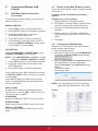
1. Unpacking and Installation
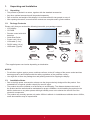
1.1. Unpacking
• This product is packed in a carton, together with the standard accessories.
• Any other optional accessories will be packed separately.
• Due to the size and weight of this display it is recommended for two people to move it.
• After opening the carton, ensure that the contents are complete and in good condition.
1.2. Package Contents
Please verify that you received the following items with your package content:
• LCD display
• CD ROM
• Remote control with AAA
batteries
• Quick Start Guide
• Power cord (1.8 m)
• VGA cable (1.8 m)
• RS232 cable (1.8 m)
• USB cable (Type B)
For EU For China
For North America For UK
*
**
*
Remote Control
and AAA Batteries
Video Signal Cable
(D-SUB to D-SUB Cable)
CD ROM
POWER
SMART
VIDEO
SOURCE
PIP
INPUTON/OFF CHANGE
BRIGHTNESSCONTRAST
DISPLAY
AUTO
ADJUST
VOL UP
VOL DOWN
EXIT
MENU
SET
AUDIO
SOURCE
OPTION
Quick Start Guide
RS232 Cable
USB Cable
* The supplied power cord varies depending on destination.
NOTES:
• For all other regions, apply a power cord that conforms to the AC voltage of the power socket and has
been approved by and complies with the safety regulations of the particular country.
• You might like to save the package box and packing material for shipping the display.
1.3. Installation Notes
• Due to the high power consumption, always use the plug exclusively designed for this product. If an
extended line is required, please consult your service agent.
• 7KHSURGXFWVKRXOGEHLQVWDOOHGRQDÀDWVXUIDFHWRDYRLGWLSSLQJ7KHGLVWDQFHEHWZHHQWKHEDFNRI
the product and the wall should be maintained for proper ventilation. Avoid installing the product in the
kitchen, bathroom or any other places with high humidity so as not to shorten the service life of the
electronic components.
• The product can normally operate only under 3000m in altitude. In installations at altitudes above 3000m,
some abnormalities may be experienced.

2
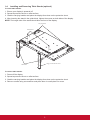
1.4. Installing and Removing Table Stands (optional)
To install table stands:
1. Ensure your display is powered off.
2. 6SUHDGDSURWHFWLYHVKHHWRQDÀDWVXUIDFH
3. Grab the carrying handles and place the display face-down on the protective sheet.
4. After inserting the stand in the guide block, tighten the screws on both sides of the display.
NOTE: The longer side of the stand should face the front of the display.
Carrying handle
Thumbscrews
Longer portions face the front
Table stand
To remove table stands:
1. Power off the display.
2. 6SUHDGDSURWHFWLYHVKHHWRQDÀDWVXUIDFH
3. Grab the carrying handles and place the display face-down on the protective sheet.
4. Remove screws using a screwdriver and place them in a safe place for reuse.

3
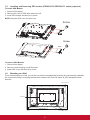
1.5. Installing and Removing OPS module (CDP4260-TL/CDP5560-TL series) (optional)
To install OPS Module:
1. Power off the display.
2. Remove the cover of OPS after take screw off.
3. ,QVHUW236PRGXOHDQGWKHQ¿[E\VFUHZ
NOTE: Keep the OPS cover for future use.
Screw
Screw
OPS
To remove OPS Module:
1. Power off the display.
2. Remove screw and plug out OPS module.
3. ,QVWDOO236FRYHUDQGWKHQ¿[E\VFUHZ
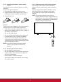
1.6. Mounting on a Wall
To mount this display to a wall, you will have to obtain a standard wall-mounting kit (commercially available).
We recommend using a mounting interface that complies with TUV-GS and/or UL1678 standard in North
America.
Protective Sheet
VESA Grid
For Tabletop standTable

4
1. Lay a protective sheet on a table, which was wrapped around the display when it was packaged, beneath
the screen surface so as not to scratch the screen face.
2. Ensure you have all accessories for mounting this display (wall mount, ceiling mount, table stand, etc).
3. Follow the instructions that come with the base mounting kit. Failure to follow correct mounting
procedures could result in damage to the equipment or injury to the user or installer. Product warranty
does not cover damage caused by improper installation.
4. For the wall-mounting kit, use M6 mounting screws (having a length 10 mm longer than the thickness of
the mounting bracket) and tighten them securely.
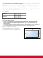
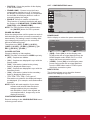
1.6.1. VESA Grid
CDP4260-TL
400(H) x 200(V) mm
200(H) x 200(V) mm
CDP5560-TL
400(H) x 400(V) mm
400(H) x 200(V) mm
200(H) x 200(V) mm
Caution:
To prevent the display from falling:
• For wall or ceiling installation, we recommend installing the display with metal brackets which are
commercially available. For detailed installation instructions, refer to the guide received with the
respective bracket.
• To lessen the probability of injury and damage resulting from fall of the display in case of earthquake or
other natural disaster, be sure to consult the bracket manufacturer for installation location.
Enclosure Ventilation Requirements
To allow heat to disperse, leave space between
surrounding objects as shown in the diagram below.
100 mm 100 mm
100 mm
100 mm

5
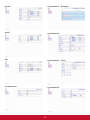
2. Parts and Functions
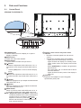
2.1. Control Panel
CDP4260-TL/CDP5560-TL:
1 2 3 4 5 6 7 8
MUTE INPUT
MENU
9
10
1
POWER button
Use this button to turn the display on or put the
display to standby.
2
MUTE button
Switch the audio mute ON/OFF.
3
INPUT button
Use this button to select the input source.
4
[ ] button
Increase the adjustment while OSD menu is on, or
increase the audio output level while OSD menu is
off.
• Used as [SET] button in the On-Screen-Display
menu.
5
[ ] button
Decrease the adjustment while OSD menu is on, or
decrease the audio output level while OSD menu is
off.
6
[ ] button
Move the highlight bar up to adjust the selected item
while OSD menu is on.
7
[ ] button
Move the highlight bar down to adjust the selected
item while OSD menu is on.
8
MENU button
Return to previous menu while OSD menu is on, or
to activate the OSD menu when OSD menu is off.
NOTE: “Keyboard Control Lock Mode” This function
completely disables the access to all Keyboard
Control functions. To enable or disable the
keyboard control lock, press both [
] and [ ]
buttons and hold down continuously for more
than 3 (three) seconds.
9
Remote control sensor and power status
indicator
• Receives command signals from the remote
control.
• Indicates the operating status of the display:
- Lights green when the display is turned on
- Lights red when the display is in standby mode
- Lights amber when the display enters APM
mode
- When {SCHEDULE} is enabled, the light blinks
green and red
- If the light blinks red, it indicates that a failure
has been detected
- Lights off when the main power of the display is
turned off
10
OPS slot
Expansion slot adapter for Open Pluggable
6SHFL¿FDWLRQ236FDUG

6
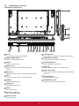
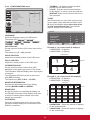
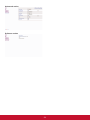
2.2. Input/Output Terminals
CDP4260-TL/CDP5560-TL:
15
16
17
18
1
2
4 5 6
7 12
8 9 10 11 13 143
1
AC IN
AC power input from the wall outlet.
2
MAIN POWER SWITCH
Switch the main power on/off.
3
USB-B
Touch connector to PC.
4
RS232C OUT
RS232C network output for the loop-through
function.
5
RS232C IN
RS232C network input for the loop-through function.
6
RJ-45
LAN port connection from your OPS device.
7
HDMI IN
HDMI video/audio input.
8
DisplayPort
DisplayPort video input.
9
DVI IN
DVI-D video input.
10
DVI OUT / VGA OUT
DVI or VGA video output.
11
VGA IN (D-Sub)
VGA video input.
12
VGA AUDIO IN
Audio input for VGA source (3.5mm stereo phone).
13
COMPONENT IN (BNC)
Component YPbPr video source input.
14
SPEAKER SWITCH
Internal speaker on/off switch.
15
AUDIO IN
Audio input from external AV device (RCA).
16
AUDIO OUT (RCA)
Audio output from the AUDIO IN jack to an external
AV device.
17
SPEAKERS OUT
External speakers output.
18
KENSINGTON LOCK
Used for security and theft prevention.

7
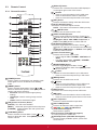
2.3. Remote Control
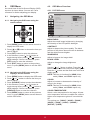
2.3.1. General functions
POWER
SMART
VIDEO
SOURCE
PIP
INPUTON/OFF CHANGE
BRIGHTNESSCONTRAST
DISPLAY
AUTO
ADJUST
VOL UP
VOL DOWN
EXIT
MENU
SET
AUDIO
SOURCE
OPTION
1
10
11
12
13
14
15
16
17
18
23
19
20
2
3
4
5
6
7
8
9
21
22
1
[POWER] button
Press to switch on the display from standby mode.
Press again to turn it off and back into standby
mode.
2
[SMART] button
Press to activate Smart Menu. Press [
] or [ ]
button to select menu options. Press [SET] button to
FRQ¿UPDQGH[LWWKHVHOHFWLRQ
• Standard: Used for normal images (factory
setting)
• Highbright: Used for moving image such as
Video
• sRGB: Used for text based images
3
[PIP] (Picture In Picture) button
[ON/OFF]: Turn PIP mode ON/OFF.
[INPUT]: Select the input signal for the sub-picture.
[CHANGE]: Toggle between the main picture and
sub picture.
4
[CONTRAST] button
Press to activate Contrast Menu. Press [ ] or [ ]
button to adjust the value. Press [MENU] button to
FRQ¿UPDQGH[LW
5
[DISPLAY] button
Press to turn on/off the information OSD displayed
on the upper right corner of the screen.
6
[ ] button
• Press to move the selection left in OSD menu.
• Press to decrease the value in OSD menu.
• Press to move the sub-picture left in PIP mode.
7
[SET] button
Press to activate the setting inside the OSD menu.
8
[AUTO ADJUST] button
Press to run the Auto Adjust function.
NOTE: This button is functional for VGA input only.
9
[ ] MUTE button
Press to turn the mute function on/off.
10
[VIDEO SOURCE] button
Press to toggle Video Source Menu. Press [
] or
[ ] button to select one of the video sources among
Displayport, DVI-D, VGA, HDMI, Component, or
Video. Press [SET@EXWWRQWRFRQ¿UPDQGH[LW
11
[AUDIO SOURCE] button
Press to toggle Audio Source Menu. Press [
] or
[ ] button to select one of the audio sources among
Displayport, HDMI, Audio1, or Audio2. Press [SET]
EXWWRQWRFRQ¿UPDQGH[LW
12
Picture Format button
Press to switch screen aspect ratio.
• For PC signal: FULL, NORMAL, CUSTOM, and
REAL.
• For Video signal: FULL, NORMAL, DYNAMIC,
CUSTOM, REAL, and 21:9.
13
[BRIGHTNESS] button
Press to toggle Brightness Menu. Press [
] or
[ ] button to adjust the value. Press [MENU] button
WRFRQ¿UPDQGH[LW
14
[ ] button
• Press to move the selection up in OSD menu.
• Press to move the sub-picture up in PIP mode.
15
[MENU] button
Press to turn the OSD menu on/off.
16
[ ] button
• Press to move the selection right in OSD menu.
• Press to increase the value in OSD menu.
• Press to move the sub-picture right in PIP mode.
17
[EXIT] button
Press to turn back to the previous OSD menu.
18
[ ] button
• Press to move the selection down in OSD menu.
• Press to move the sub-picture down in PIP mode.
19
[VOL UP] button
Press to increase the audio output level.
20
[VOL DOWN] button
Press to decrease the audio output level.
21
COLOR buttons
(CDP/CDX Not Support)
Select tasks or options.
22
PLAY buttons (CDP/CDX Not Support)
&RQWUROSOD\EDFNRIPHGLD¿OHV
23
[OPTION] button (CDP/CDX Not Support)
Access currently available options, picture and
sound menus.

8
2.3.2. Inserting the batteries in the remote
control
The remote control is powered by two 1.5V AAA
batteries.
To install or replace batteries:
1. Press and then slide the cover to open it.
2. Align the batteries according to the (+) and (–)
indications inside the battery compartment.
3. Replace the cover.
Caution:
The incorrect use of batteries can result in leaks or
bursting. Be sure to follow these instructions:
• Place “AAA” batteries matching the (+) and (–)
signs on each battery to the (+) and (–) signs of
the battery compartment.
• Do not mix battery types.
• Do not combine new batteries with used ones.
It causes shorter life or leakage of batteries.
• Remove the dead batteries immediately to
prevent them from liquid leaking in the battery
compartment. Don’t touch exposed battery acid,
as it can damage your skin.
NOTE: If you do not intend to use the remote
control for a long period, remove the
batteries.
2.3.3. Handling the remote control
• Do not subject to strong shock.
• Do not allow water or other liquid to splash the
remote control. If the remote control gets wet,
wipe it dry immediately.
• Avoid exposure to heat and steam.
• Other than to install the batteries, do not open
the remote control.
2.3.4. Operating range of the remote control
Point the top of the remote control toward the
display’s remote control sensor when pressing a
button.
Use the remote control within a distance of less
than 10m/33ft from the display’s sensor, and
a horizontal and vertical angle of less than 30
degrees.
NOTE: The remote control may not function
properly when the remote control sensor on
the display is under direct sunlight or strong
illumination, or when there is an obstacle in
the path of signal transmission.
30 30
POWER
SMART
VIDEO
SOURCE
PIP
INPUTON/OFF CHANGE
BRIGHTNESSCONTRAST
DISPLAY
AUTO
ADJUST
VOL UP
VOL DOWN
EXIT
MENU
SET
AUDIO
SOURCE
OPTION

9
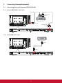
3. Connecting External Equipment
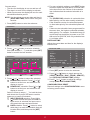
3.1. Connecting External Equipment (DVD/VCR/VCD)
3.1.1. Using COMPONENT video input
DVD / VCR / VCD
[AUDIO IN]
[COMPONENT IN]
(Pr/Pb/Y)
COMPONENT Out
(YPbPr)
Audio Out
[R]
[L]
3.1.2. Using HDMI video input
DVD / VCR / VCD
HDMI Out
[HDMI IN]

10
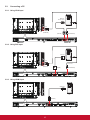
3.2. Connecting a PC
3.2.1. Using VGA input
PC
[VGA IN] [VGA AUDIO IN]
VGA Out
D-Sub 15 pin
Audio Out
[AUDIO IN]
[R]
[L]
3.2.2. Using DVI input
PC
[VGA AUDIO IN]
DVI Out
Audio Out
[AUDIO IN]
[R]
[L]
[DVI IN]
3.2.3. Using HDMI input
PC
HDMI Out
[HDMI IN]

11
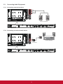
3.3. Connecting Audio Equipment
3.3.1. Connecting external speakers
External speakers
3.3.2. Connecting an external audio device
Stereo Amplier
[AUDIO OUT]
[R]
[L]
Audio In

12
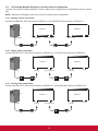
3.4. Connecting Multiple Displays in a Daisy-chain Configuration
<RXFDQLQWHUFRQQHFWPXOWLSOHGLVSOD\VWRFUHDWHDGDLV\FKDLQFRQ¿JXUDWLRQIRUDSSOLFDWLRQVVXFKDVDYLGHR
wall.
NOTE: 0D[LPXPGLVSOD\V[FDQEHXVHGLQDGDLV\FKDLQFRQ¿JXUDWLRQ
3.4.1. Display control connection
Connect the [RS232C OUT] connector of DISPLAY 1 to the [RS232C IN] connector of DISPLAY 2.
PC
DISPLAY 1 DISPLAY 2
[RS-232C IN][RS-232C] [RS-232C OUT] [RS-232C IN]
3.4.2. Digital video connection
Connect the [DVI OUT / VGA OUT] connector of DISPLAY 1 to the [DVI IN] connector of DISPLAY 2.
PC
DISPLAY 1 DISPLAY 2
[DVI IN][DVI] [DVI/VGA OUT] [DVI IN]
3.4.3. Analog video connection
Connect the [DVI OUT / VGA OUT] connector of DISPLAY 1 to the [VGA IN] connector of DISPLAY 2.
PC
DISPLAY 1 DISPLAY 2
[VGA IN][VGA] [DVI/VGA OUT] [VGA IN]
Page is loading ...
Page is loading ...
Page is loading ...
Page is loading ...
Page is loading ...
Page is loading ...
Page is loading ...
Page is loading ...
Page is loading ...
Page is loading ...
Page is loading ...
Page is loading ...
Page is loading ...
Page is loading ...
Page is loading ...
Page is loading ...
Page is loading ...
Page is loading ...
Page is loading ...
Page is loading ...
Page is loading ...
Page is loading ...
Page is loading ...
Page is loading ...
Page is loading ...
Page is loading ...
Page is loading ...
Page is loading ...
-
 1
1
-
 2
2
-
 3
3
-
 4
4
-
 5
5
-
 6
6
-
 7
7
-
 8
8
-
 9
9
-
 10
10
-
 11
11
-
 12
12
-
 13
13
-
 14
14
-
 15
15
-
 16
16
-
 17
17
-
 18
18
-
 19
19
-
 20
20
-
 21
21
-
 22
22
-
 23
23
-
 24
24
-
 25
25
-
 26
26
-
 27
27
-
 28
28
-
 29
29
-
 30
30
-
 31
31
-
 32
32
-
 33
33
-
 34
34
-
 35
35
-
 36
36
-
 37
37
-
 38
38
-
 39
39
-
 40
40
-
 41
41
-
 42
42
-
 43
43
-
 44
44
-
 45
45
-
 46
46
-
 47
47
-
 48
48


ViewSonic CDP4260-TL User guide
- Category
- Public displays
- Type
- User guide
Ask a question and I''ll find the answer in the document
Finding information in a document is now easier with AI
Related papers
-
ViewSonic CDM5500T User guide
-
ViewSonic CDE6510-S User guide
-
ViewSonic CDP5560-L User guide
-
ViewSonic CDE4600-L-S User guide
-
ViewSonic CDE4600-L User manual
-
ViewSonic CDE5502 User guide
-
ViewSonic CDE5510 User guide
-
ViewSonic CDX5552-S User guide
-
-
ViewSonic CDM5500R-S User guide
Other documents
-
 Novita N10002 Datasheet
-
BenQ SL461A User manual
-
Philips BDL5586XL User manual
-
Lorex 4KHDIP1610M User manual
-
Hitachi DS55MU01 User manual
-
Dynascan DS46LX2 User manual
-
Sharp PN-L601B Quick start guide
-
HP ZR2240w 21.5-inch LED Backlit IPS Monitor Reference guide
-
Ricoh D6500 Operating instructions
-
Toshiba TD-X461M User guide
