Dynascan DS46LX2 User manual

Category
Public displays
Type
User manual

This manual is also suitable for

User Manual
Professional LCDs
Version 4.00
The use
of diagrams and illustrations in the manual for reference only, actual product may be different.
Product design and specifications are subject to change without notice
Pr
of
es
si
o
nal
LC
Ds
DS32CR \DS42CR \DS46CR \DS46LX \DS55LX Series
ii
DS32CR \DS42CR \DS46CR \DS46LX \DS55LX Series
iii
Safety Instructions
Read and follow these instructions when connecting
and using your Public Information Display:
• Unplug the display if you are not going to
use it for an extensive period of time.
• Unplug the display if you need to clean it
with a slightly damp cloth. The screen many
be wiped with a dry cloth when the power is
of
f. However, never use alcohol, solvents or
ammonia-based liquids.
• Consult a service technician if the display
does not operate normally when you have
followed the instructions in this manual.
• The casing cover should be opened only by
qualiedservicepersonnel.
• Keep the display out of direct sunlight and
away from stoves or any other heat source.
• Remove any object that could fall into
the vents or prevent proper cooling of the
display’s electronics.
• Do not block the ventilation holes on the
cabinet.
• Keep the display dry
. To avoid electric
shock, do not expose it to rain or excessive
moisture.
• If turning off the display by detaching power
cable or DC power cord, wait for 6 seconds
before attach the power cable or DC power
cord for normal operation.
• To avoid the risk of shock or permanent
damage to the set do not expose the display
to rain or excessive moisture.
• When positioning the display, make sure the
power plug and outlet are easily accessible.
• IMPORTANT: Always activate a screen
saver program during your application. If
a still image in high contrast remains on
the screen for an extended period of time,
it may leave an ‘after-image’ or ‘ghost
image’ on the front of the screen. This is
a well-known phenomenon that is caused
by the shortcomings inherent in the LCD
technology. In most cases the afterimage
will disappear gradually over a period of
time after the power has been switched off.
Be aware that the after-image symptom
cannot be repaired and is not covered under
warranty.
Warnings and Precautions
KNOW THESE SAFETY SYMBOLS
CAUTION: TO REDUCE THE RISK OF ELECTRIC SHOCK,
DO NOT REMOVE COVER (OR BACK).
NO USER SERVICEABLE PARTS INSIDE.
REFER SERVICING TO QUALIFIED SERVICE
PERSONNEL.
This symbol indicates high voltage is present
inside. It is dangerous to make any kind of
contact with any inside part of this product.
This symbol alerts you that important literature
concerning operation and maintenance has
been included with this product.
Note to CATV system installer
: This reminder is provided to
call CATV system installer’s attention to Article 820-40 of the
National Electrical Code (Section 54 of Canadian Electrical
Code, Part I), that provides guidelines for proper grounding and,
inparticular,speciesthatthecablegroundshallbeconnected
to the grounding system of the building as close to the point of
cable entry as practical.
CAUTION
: FCC/CSA regulations state that any unauthorized
changesormodicationstothisequipmentmay
void the user
s authority to operate it.
CAUTION
: To prevent electric shock, match the wide blade
of plug to the wide slot, and fully insert the plug.
IMPORTANT
: One Federal Court has held that unauthorized
recording of copyrighted TV programs is an
infringement of U.S. copyright laws. Certain
Canadian programs may also be copyrighted and
any unauthorized recording in whole or in part
may be in violation of these rights.
T
O PREVENT DAMAGE WHICH MAY RESULT IN FIRE
OR ELECTRIC SHOCK HAZARD, DO NOT EXPOSE THIS
APPLIANCE TO RAIN OR MOISTURE.
The Socket-outlet shall be installed near the apparatus and
shall be easily accessible.
DS32CR \DS42CR \DS46CR \DS46LX \DS55LX Series
iv
Regulatory Information
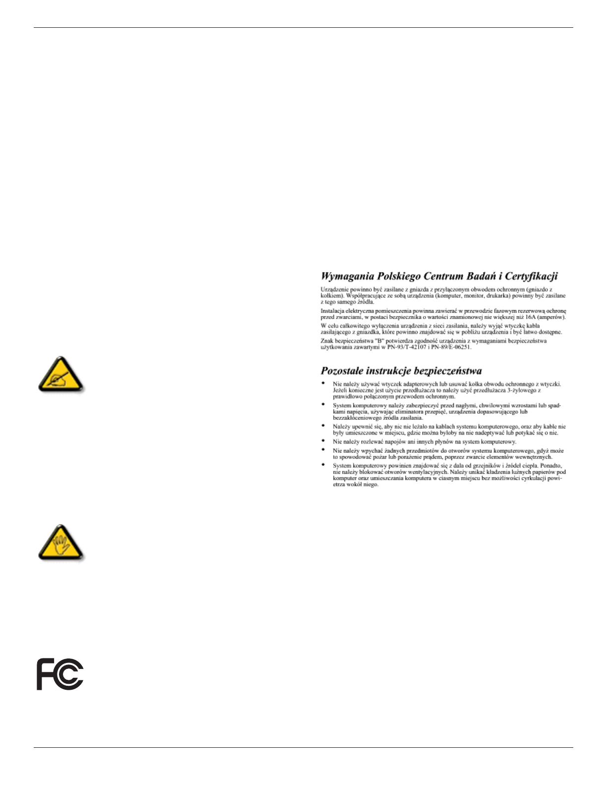
Polish Center for Testing and Certication
Notice
The equipment should draw power from a socket with an
attached protection circuit (a three-prong socket). All equipment
that works together (computer, monitor, printer, and so on)
should have the same power supply source.
The phasing conductor of the room’s electrical installation
should have a reserve short-circuit protection device in the form
of a fuse with a nominal value no larger than 16 amperes (A).
To completely switch off the equipment, the power supply cable
must be removed from the power supply socket, which should
be located near the equipment and easily accessible.
Aprotectionmark“B”conrmsthattheequipmentisin
compliance with t
he protection usage requirements of standards
PN-93/T-42107 and PN-89/E-06251.
Electric, Magnetic and Electronmagnetic
Fields (“EMF”)
1. We manufacture and sell many products targeted at
consumers, which, like any electronic apparatus, in general
have the ability to emit and receive electromagnetic signals.
2. One of our leading Business Principles is to take all
necessary health and safety measures for our products, to
comply with all applicable legal requirements and to stay
well within the EMF standards applicable at the time of
producing the products.
3. We are committed to develop, produce and market products
that cause no adverse health ef
fects.
4. Weconrmthatifitsproductsarehandledproperlyfortheir
intendeduse,theyaresafetouseaccordingtoscientic
evidence available today.
5. We play an active role in the development of international
EMF and safety standards, enabling us to anticipate further
developments in standardization for early integration in its
products.
CE Declaration of Conformity
We declare under our responsibility that the product is in
conformity with the following standards:
• EN60950-1:2006+A1
1:2009 (Safety requirement of
Information Technology Equipment)
• EN55022:2006+A1:2007 (Radio Disturbance requirement of
Information Technology Equipment)
• EN55024:1998+A1:2001+A2:2003 (Immunity requirement of
Information Technology Equipment)
• EN61000-3-2:2006 (Limits for Harmonic Current Emission)
• EN61000-3-3:2008 (Limitation of Voltage Fluctuation and
Flicker) following provisions of directives applicable
• 2006/95/EC (Low Voltage Directive)
• 2004/108/EC (EMC Directive)
• 2005/32/EC (EuP, Energy-using Product Directive) EC No.
642/2009 Implementing
• 93/68/EEC (Amendment of EMC and Low Voltage Directive)
and is produced by a manufacturing organization on
ISO9000 level.
Federal Communications Commission (FCC)
Notice (U.S. Only)
This equipment has been tested and found
to comply with the limits for a Class B digital
device, pursuant to Part 15 of the FCC Rules.
These limits are designed to provide reasonable
protection against harmful interference when
the equipment is operated in a commercial
environment. This equipment generates, uses
and can radiate radio frequency energy and,
if not installed and used in accordance with
the instructions manual, may cause harmful
interference to radio communications. Operation
of this equipment in a residential area is likely
to cause harmful interference in which case the
user will be required to correct the interference
at his own expense.
Changesormodicationsnotexpressly
approved by the party responsible for
compliance could void the user
s authority to
operate the equipment.
Use only RF shielded cable that was supplied with the display
when connecting this display to a computer device.
Topreventdamagewhichmayresultinreorshockhazard,do
not expose this appliance to rain or excessive moisture.
THIS CLASS B DIGITAL
APPARATUS MEETS ALL
REQUIREMENTS OF THE CANADIAN INTERFERENCE-
CAUSING EQUIPMENT REGULATIONS.
This device complies with Part 15 of the FCC
Rules. Operation is subject to the following
two conditions: (1) this device may not cause
harmful interference, and (2) this device must
accept any interference received, including
interference that may cause undesired
operation.
DS32CR \DS42CR \DS46CR \DS46LX \DS55LX Series
v
Information for U.K. only
How to connect a plug:
The wires in the mains lead are coloured in accordance with the
following code:
BLUE - “NEUTRAL” (“N”)
BROWN - “LIVE” (“L”)
GREEN & YELLOW - “EAR
TH” (“E”)
1. The GREEN & YELLOW wire must be connected to the
terminal in the plug which is marked with the letter “E” or
by the Earth symbol or coloured GREEN or GREEN &
YELLOW
.
2. The BLUE wire must be connected to the terminal which is
marked with the letter “N” or coloured BLACK.
3. The BROWN wire must be connected to the terminal which
marked with the letter “L” or coloured RED.
Before replacing the plug cover, make certain that the cord grip
is clamped over the sheath of the lead - not simply over the
three wires.
WARNING - THIS
APPLIANCE MUST BE EARTHED.
Important:
This apparatus is supplied with an approved moulded 13A
plug.
T
o change a fuse in this type of plug proceed as follows:
(A)
(B)
1. Remove fuse cover and fuse.
2. Fit new fuse which should be a BS 1362 5A,A.S.T.A. or BSI
approved type.
3. Retthefusecover.
Ifthettedplugisnotsuitableforyoursocketoutlets,itshould
becutoffandanappropriate3-pinplugttedinitsplace.
If the mains plug contains a fuse, this should have a value of
5A. If a plug without a fuse is used, the fuse at the distribution
board should not be greater than 5A.
NOTE: The severed plug must be destroyed to avoid a
possible shock hazard should it be inserted into a 13A
socket elsewhere.
DS32CR \DS42CR \DS46CR \DS46LX \DS55LX Series
vi
China RoHS
子信制标识 (RoHS法规标示) 毒有或元素
含量
毒有或元素
(Pb)
(Hg)
(Cd)
价铬
(Cr 6+)
溴联
(PBB)
二苯
(PBDE)
O O O O O O
X X O O O O
电路板组 X O O O O O
(遥控线连接线)
X O O O O O
遥控 X O O O O O
O: 表示该有毒有害物质在该部所有质材的含量 SJ/T11363-2006 准规限量要.
X: 表示该有毒有害物质至该部质材的含量超 SJ/T11363-2006 规定限量要
.
10
環保使用期限
此標識指期限(十年),電子信息產品中含有的有毒有害物質或元素在正常使用的條件下不會發生外泄或突變
,電子信息產品用戶使用該電子信息產品不會對環境造成嚴重污染或對其人身、財產造成嚴重損害的期限。
仅适用于海拔 2000m 以下地区安全使用
DS32CR \DS42CR \DS46CR \DS46LX \DS55LX Series
vii
North Europe (Nordic Countries) Information
Placering/Ventilation
VARNING:
FÖRSÄKRA DIG OM
ATT HUVUDBRYTARE OCH
UTTAG ÄR LÄTÅTKOMLIGA, NÄR DU STÄLLER DIN
UTRUSTNING PÅPLATS.
Placering/Ventilation
ADVARSEL:
SØRG VED PLACERINGEN FOR, A
T NETLEDNINGENS
STIK OG STIKKONTAKT ER NEMT TILGÆNGELIGE.
Paikka/Ilmankierto
VAROITUS:
SIJOITA
LAITE SITEN, ETTÄ VERKKOJOHTO VOIDAAN
TARVITTAESSA HELPOSTI IRROTTAA PISTORASIASTA.
Plassering/Ventilasjon
ADVARSEL:
NÅR DETTE UTSTYRET PLASSERES, MÅ DU PASSE PÅ
AT KONTAKTENE FOR STØMTILFØRSEL ER LETTE Å NÅ.
End-of-Life Disposal
Your new Public Information Display contains materials that can
be recycled and reused. Specialized companies can recycle
your product to increase the amount of reusable materials and
to minimize the amount to be disposed of.
Pleasendoutaboutthelocalregulationsonhowtodisposeof
your old display from your local dealer.
(For customers in Canada and U.S.A.)
This product may contain lead and/or mercury. Dispose of in
accordance to local-state and federal regulations. For additional
information on recycling contact www
.eia.org (Consumer
Education Initiative)
Waste Electrical and Electronie Equipment-
WEEE
Attention users in European Union private
households
This marking on the product or on its packaging
illustrates that, under European Directive
2002/96/EG governing used electrical and
electronic appliances, this product may
not be disposed of with normal household
waste. You are responsible for disposal of
this equipment through a designated waste
electrical and electronic equipment collection.
To determine the locations for dropping off such
waste electrical and electronic, contact your
localgovernmentofce,thewastedisposal
organization that serves your household or the
store at which you purchased the product.
Attention users in United States:
Like all LCD products, this set contains a lamp with Mercury
.
Please dispose of according to all Local, State and Federal
Laws. For the disposal or recycling information, contact: www
.
mygreenelectronics.com or www.eiae.org.
End of Life Directives-Recycling
Your new Public Information Display contains
several materials that can be recycled for new
users.
Like all LCD produces, this set contains a lamp
with Mercury
. Please dispose of according to all
Local, State, and Federal laws.
As an ENERGY ST
AR Partner, we have
determined that this product meets the
ENERGYSTARguidelinesforenergyefciency.
DS32CR \DS42CR \DS46CR \DS46LX \DS55LX Series
viii
Table Of Contents
1. Unpacking and Installation ............................................................................................................1
1.1. Unpacking ...................
.............................................................................................................
1
1.2. Package Contents ....................................................................................................................1
1.3. Installation Notes ....................
..................................................................................................
1
1.4. Installing and Removing
Table Stands (optional)
.....................................................................2
1.5. Mounting on a Wall ....................
...............................................................................................
3
2. Parts and Functions .......................................................................................................................5
2.1. Control Panel ...................
........................................................................................................
5
2.2. Input/Output Terminals .............................................................................................................6
2.3. Remote Control ........................................................................................................................7
2.3.1. General functions ..........
.................................................................................................
7
2.3.2. Inserting the batteries in the remote control ..........
.........................................................
8
2.3.3. Handling the remote control ..........
.................................................................................
8
2.3.4. Operating range of the remote control ...........................................................................8
3. Connecting External Equipment ...................................................................................................9
3.1. Using the Switch Cover ............................................................................................................9
3.2. Connecting External Equipment (DVD/VCR
/VCD)
...................
.............................................
10
3.2.1. Using COMPONENT video input .................................................................................10
3.2.2. Using HDMI video input ...............................................................................................10
3.3. Connecting a PC ....................................................................................................................11
3.3.1. Using VGA input ..........
.................................................................................................
11
3.3.2. Using DVI input ............................................................................................................11
3.3.3. Using HDMI input ..........
...............................................................................................
12
3.4. External Audio Connection .....................................................................................................13
3.4.1. Connecting external speakers .....................................................................................13
3.4.2. Connecting an external audio device ..........
.................................................................
13
3.5. ConnectingMultipleDisplaysinaDaisy-chainConguration ................................................14
3.5.1. Video connection .........................................................................................................14
3.5.2. Audio connection .........................................................................................................14
4. OSD Menu ......................................................................................................................................15
4.1. Navigating the OSD Menu ...................
.................................................................................
15
4.1.1. Navigating the OSD menu using the remote control ..........
..........................................
15
4.1.2. Navigating the OSD menu using the display’s control buttons ....................................15
4.2. OSD Menu Overview ...................
..........................................................................................
15
4.2.1. PICTURE menu ...........................................................................................................15
4.2.2. SCREEN menu ............................................................................................................16
4.2.3. AUDIO menu ..........
......................................................................................................
17
4.2.4. PIP menu .....................................................................................................................17
DS32CR \DS42CR \DS46CR \DS46LX \DS55LX Series
ix
4.2.5. CONFIGURATION1 menu ...........................................................................................18
4.2.6. CONFIGURATION2 menu ...........................................................................................19
4.2.7. CONFIGURATION3 menu ...........................................................................................20
4.2.8. ADVANCED OPTION menu ........................................................................................21
5. Input Mode .....................................................................................................................................23
6. Cleaning and Troubleshooting ....................................................................................................24
6.1. Cleaning .................................................................................................................................24
6.2. Troubleshooting ....................
..................................................................................................
25
7. Technical Specications ..............................................................................................................26
DS32CR \DS42CR \DS46CR \DS46LX \DS55LX Series
1
1. Unpacking and Installation
1.1. Unpacking
• This product is packed in a carton, together with the standard accessories.
• Any other optional accessories will be packed separately.
• Due to the size and weight of this display it is recommended for two people to move it.
• After opening the carton, ensure that the content is in good condition and complete.
1.2. Package Contents
Please verify that you received the following items with your package content:
• CD ROM
• Remote control with
AAA
batteries
• Power cord (1.8 m)
• VGA cable (1.8 m)
•
•
Power switch cover
Screw for Power switch cover
(M3x8)
* The supplied power cord varies depending on destination.
For EU For China
For North America For UK
POWER
SMART
VIDEO
SOU
RCE
PIP
INPUTON/OFF CHANGE
BRIGHTNESSCONTRAST
DISPLAY
AUTO
ADJUST
MUTE
VOL UP
VOL DOWN
EXIT
MENU
SET
AUDIO
SOURCE
CD ROM (Optional)
Power switch cover
Remote Control
and AAA Batteries
Screw for Power switch cove
r
(M3 x 8) x 1
Video Signal Cable
(D-SUB to D-SUB Cable)
NOTES:
• Please make sure that for all other regions, apply a power cord that conforms to the AC voltage of the power socket and has been
approved by and complies with the safety regulations of the particular country
.
• You might like to save the package box and packing material for shipping the display.
1.3. Installation Notes
• Due to the high power consumption, always use the plug exclusively designed for this product. If an extended line is required, please
consult your service agent.
•
Theproductshouldbeinstalledonaatsurfacetoavoidtipping.Thedistancebetweenthebackoftheproductandthewallshould
be maintained for proper ventilation. A
void installing the product in the kitchen, bathroom or any other places with high humidity so as
not to shorten the service life of the electronic components.
• The product can normally operate only under 2000m in altitude. In installations at altitudes above 2000m, some abnormalities may be
experienced.
DS32CR \DS42CR \DS46CR \DS46LX \DS55LX Series
2
1.4. Installing and Removing Table Stands (optional)
To install table stands:
1. Power off the display
.
2. Spreadaprotectivesheetonaatsurface.
3. Grab the carrying handles and place the display face-down on the protective sheet.
4. After inserting the stand in the guide block, tighten the screws on both sides of the display.
NOTE: The long-end side of the stand should face to the front while installing.
Thumbscrews
Carrying handle
Longer portions face the front
Table stand
DS32CR series\DS42CR series\DS46CR series
DS46LX2
Carrying handle
Thumbscrews
Table stand
DS55LX2
Carrying handle
Thumbscrews
Table stand
DS32CR \DS42CR \DS46CR \DS46LX \DS55LX Series
3
T
o remove table stands:
1. Power off the display
.
2. Spreadaprotectivesheetonaatsurface.
3. Grab the carrying handles and place the display face-down on the protective sheet.
4. Remove screws using a screwdriver and place them in a safe place for reuse.
1.5. Mounting on a W
all
To mount this display to a wall, you will have to obtain a standard wall-mounting kit (commercially available). W
e recommend using a
mounting interface that complies with TUV-GS and/or UL1678 standard in North America.
DS32CR series\DS42CR series\DS46CR series
100
200
200 100
Protective Sheet
Tabletop stand
Table
DS46LX2
100
200
200
100
Protective Sheet
Tabletop stand
Table
400
400
Protective Sheet
Tabletop standTable
DS55LX2
DS32CR \DS42CR \DS46CR \DS46LX \DS55LX Series
4
1. Lay a protective sheet on a table, which was wrapped around the display when it was packaged, beneath the screen surface so as
not to scratch the screen face.
2. Ensure you have all accessories for mounting this display (wall mount, ceiling mount, table stand, etc).
3. Follow the instructions that come with the base mounting kit. Failure to follow correct mounting procedures could result in damage to
the equipment or injury to the user or installer. Product warranty does not cover damage caused by improper installation.
4. For the wall-mounting kit, use M6 mounting screws (having a length 10 mm longer than the thickness of the mounting bracket) and
tighten them securely.
Caution:
T
o prevent the display from falling:
• For wall or ceiling installation, we recommend installing the display with metal brackets which are commercially available. For
detailed
installation instructions, refer to the guide received with the respective bracket.
• To lessen the probability of injury and damage resulting from fall of the display in case of earthquake or other natural disaster, be sure
to consult the bracket manufacturer for installation location.
Ventilation Requirements for enclosure locating
To allow heat to disperse, leave space between surrounding objects as shown in the diagram below
.
100 mm 100 mm
100 mm
100 mm
DS32CR \DS42CR \DS46CR \DS46LX \DS55LX Series
5
2. Parts and Functions
2.1. Control Panel
MUTE INPUT
MENU
1
9
2 3 4 5 6 7 8
DS32CR \DS42CR \DS46CR series
MUTE INPUT
MENU
1 2 3 4 5 6 7 8
DS46LX2
5
4
3
21 6 7
8
DS55LX2
9
MENU
1
POWER button
Use this button to turn the display on or put the display to
standby
.
2
MUTE button
Switch the audio mute ON/OFF.
3
INPUT button
• Use this button to select the input source.
• When the On Screen Display menu is active, this is also
used as the [SET] button.
4
[ ] button
Increase the adjustment while OSD menu is on, or increase
the audio output level while OSD menu is off.
5
[ ] button
Decrease the adjustment while OSD menu is on, or
decrease the audio output level while OSD menu is off.
6
[ ] button
Move the highlight bar up to adjust the selected item while
OSD menu is on.
7
[ ] button
Move the highlight bar down to adjust the selected item
while OSD menu is on.
8
MENU button
Return to previous menu while OSD menu is on, or to
activate the OSD menu when OSD menu is off.
NOTE: Keyboard Control Lock Mode” This function
completely disables the access to all Keyboard Control
functions.
To enable or disable the keyboard control
lock, press both [
] and [ ] buttons and hold down
continuously for more than 3 (three) seconds.
9
Remote control sensor and power status indicator
• Receives command signals from the remote control.
• Indicates the operating status of the display:
- Lights green when the display is turned on
- Lights red when the display is in standby mode
- Lights amber when the display enters DPMS mode
- When {SCHEDULE}
is enabled, the light blinks green
and red
- If the light blinks red, it indicates that a failure has been
detected
- Off when the main power of the display is turned of
f
DS32CR \DS42CR \DS46CR \DS46LX \DS55LX Series
7
2.3. Remote Control
2.3.1. General functions
POWER
SMART
VIDEO
SOURCE
PIP
INPUTON/OFF CHANGE
BRIGHTNESSCONTRAST
DISPLAY
AUTO
ADJUST
MUTE
VOL UP
VOL DOWN
EXIT
MENU
SET
AUDIO
SOURCE
1
10
11
12
13
14
15
16
17
18
19
20
2
3
4
5
6
7
8
9
1
[POWER] button
Press to switch on the display from standby mode. Press
again to turn it off and back into standby mode.
2
[SMART] button
Press to activate Smart Menu. Press [ ] or [ ] button to
select menu options. Press [SET]buttontoconrmandexit
the selection.
Standard: Used for normal images (factory setting)
Highbright: Used for moving image such as Video
sRGB: Used for text based images
3
[PIP] (Pictu
re In Picture) button
[ON/OFF]:
T
urn PIP
mode ON/OFF.
[INPUT]: Select the input signal for the sub-picture.
[CHANGE]: Toggle between the main picture and sub
picture.
4
[CONTRAST] button
Press to activate Contrast Menu. Press [ ] or [ ] button to
adjust the value. Press [MENU]buttontoconrmandexit.
5
[DISPLAY] button
Press to turn on/off the information OSD displayed on the
upper right corner of the screen.
6
[ ] button
• Press to move the selection left in OSD menu.
• Press to decrease the value in OSD menu.
• Press to move the sub-picture left in PIP mode.
7
[SET] button
Press to activate the setting inside the OSD menu.
8
[AUTO ADJUST]
button
Press to run the Auto
Adjust function.
NOTE: This button is functional for VGA input only.
9
[MUTE] button
Press to turn the mute function on/of
f.
10
[VIDEO SOURCE] button
Press to toggle Video Source Menu. Press [ ] or [
] button to select one of the video sources among HDMI,
DVI-D, VGA, DVD / HD, VIDEO-S, or VIDEO . Press [SET]
buttontoconrmandexit.
11
[AUDIO SOURCE] button
Press t
o toggle Audio Source Menu. Press [
]
or [
]
button
to select one of the audio sources among HDMI, AUDIO1,
AUDIO2, or AUDIO3. Press [SET
]buttontoconrmand
exit.
12
Picture Format button
Press to switch screen aspect ratio.
• For PC signal: FULL, NORMAL, CUSTOM
and REAL.
• For Video signal: FULL, NORMAL, DYNAMIC, CUSTOM
and REAL.
13
[BRIGHTNESS] button
Press to toggle Brightness Menu. Press [ ] or [ ] button to
adjust the value. Press [MENU]buttontoconrmandexit.
14
[ ] button
• Press to move the selection up in OSD menu.
• Press to move the sub-picture up in PIP mode.
15
[MENU] button
Press to turn the OSD menu on/off.
16
[ ] button
• Press to move the selection right in OSD menu.
• Press to increase the value in OSD menu.
• Press to move the sub-picture right in PIP mode.
17
[EXIT] button
Press to turn back to the previous OSD menu.
18
[ ] button
• Press to move the selection down in OSD menu.
• Press to move the sub-picture down in PIP
mode.
19
[VOL UP] button
Press to increase the audio output level.
20
[VOL DOWN] button
Press to decrease the audio output level.
DS32CR \DS42CR \DS46CR \DS46LX \DS55LX Series
8
2.3.2. Inserting the batteries in the remote
control
The remote control is powered by two 1.5V AAA
batteries.
To install or replace batteries:
1. Press and then slide the cover to open it.
2. Align the batteries according to the (+) and (–) indications
inside the battery compartment.
3. Replace the cover.
Caution:
The incorrect use of batteries can result in leaks or bursting. Be
sure to follow these instructions:
• Place “AAA” batteries matching the (+) and (–) signs on each
battery to the (+) and (–) signs of the battery compartment.
• Do not mix battery types.
• Do not combine new batteries with used ones. It causes
shorter life or leakage of batteries.
• Remove the dead batteries immediately to prevent them
from liquid leaking in the battery compartment. Don’t touch
exposed battery acid, it cause damage to your skin.
NOTE: If you do not intend to use the remote control for a long
period, remove the batteries.
2.3.3. Handling the remote control
• Do not subject to strong shock.
• Do not allow water or other liquid to splash the remote
control. If the remote control gets wet, wipe it dry
immediately.
• A
void exposure to heat and steam.
• Other than to install the batteries, do not open the remote
control.
2.3.4. Operating range of the remote control
Point the top of the remote control toward the display’s remote
control sensor when pressing a button.
• Environment:under 200-400 cd/m
2
• RC sensor for DS55LX2/DS46LX2 only use in 30cm.
(sensor behind in panel)
• As below Operation angle and distance not use for
DS55LX2/DS46LX2.
Operation Angle RC operational distance
Please 0
O
(for H&V) ≥10m(controlfromthefront)
30
O
(for H&V) ≥5m(controlfromthefront)
45
O
(for H only) ≥2m(controlfromthefront)
NO
TE:
The
remote control may not function properly when the
remote control sensor on the display is under direct
sunlight or strong illumination, or when there is an
obstacle in the path of signal transmission.
30 30
DS32CR /DS42CR /DS46CR series
30 30
DS55LX2 /DS46LX2
DS32CR \DS42CR \DS46CR \DS46LX \DS55LX Series
9
3. Connecting External Equipment
3.1. Using the Switch Cover
A cover for the power switch is provided to prevent the display from being turned on or of
f accidentally.
To lock the cover into position:
1. Align and insert the cover to the indentation located beside the main switch.
2. Use the screw to lock the cover.
DS32CR*:
1
2
Screw
Power switch cover
DS42CR* / DS46CR*:
1
2
Screw
Power switch cover
DS32CR \DS42CR \DS46CR \DS46LX \DS55LX Series
10
3.2. Connecting External Equipment (DVD/VCR/VCD)
3.2.1. Using COMPONENT video input
Audio Output
To [AUDIO IN 2, 3]
DVD / VCR / VCD
COMPONENT
(YPbPr)
COMPONENT
(YPbPr)
3.2.2. Using HDMI video input
DVD / VCR / VCD
HDMI connector
HDMI connector
DS32CR \DS42CR \DS46CR \DS46LX \DS55LX Series
11
3.3. Connecting a PC
3.3.1. Using VGA input
To [VGA IN]
PC or IBM compatible
From analog VGA output
Mini D-Sub 15 pin
From audio outp
ut
To [AUDIO IN 1, 2, 3]
3.3.2. Using DVI input
From audio output
To [DVI IN]
PC or IBM compatible
From DVI outpu
t
To [AUDIO IN 1, 2, 3]
  • Page 1 1
  • Page 2 2
  • Page 3 3
  • Page 4 4
  • Page 5 5
  • Page 6 6
  • Page 7 7
  • Page 8 8
  • Page 9 9
  • Page 10 10
  • Page 11 11
  • Page 12 12
  • Page 13 13
  • Page 14 14
  • Page 15 15
  • Page 16 16
  • Page 17 17
  • Page 18 18
  • Page 19 19
  • Page 20 20
  • Page 21 21
  • Page 22 22
  • Page 23 23
  • Page 24 24
  • Page 25 25
  • Page 26 26
  • Page 27 27
  • Page 28 28
  • Page 29 29
  • Page 30 30
  • Page 31 31
  • Page 32 32
  • Page 33 33
  • Page 34 34
  • Page 35 35
  • Page 36 36
  • Page 37 37
  • Page 38 38
  • Page 39 39
  • Page 40 40
  • Page 41 41
  • Page 42 42
  • Page 43 43
  • Page 44 44
  • Page 45 45
  • Page 46 46

Dynascan DS46LX2 User manual

Category
Public displays
Type
User manual
This manual is also suitable for

Ask a question and I''ll find the answer in the document

Finding information in a document is now easier with AI