Page is loading ...

Page 1
WARNING
If the information in this manual is not followed exactly a fire or explosion may result, causing
property damage, personal injury or death.
North America’s Best
CONGRATULATIONS! You are now the proud owner of one of the finest gas stoves on the market - the QUADRA-FIRE.
DV-40 STEP TOP DIRECT VENT FREESTANDING GAS STOVE (DV-40 STEP)
INSTALLATION, OPERATION, VENTING AND MAINTENANCE INSTRUCTIONS
SAVE THESE INSTRUCTIONS
401 N. Wynne Street
Colville, WA 99114
www.aladdinhearth.com
Revised (8/98)
FOR YOUR SAFETY
DO NOT store or use gasoline or other flammable vapors and liquids in the vicinity of this or any other
appliance.
WHAT TO DO IF YOU SMELL GAS
• Extinguish any open flame.
• Open windows.
• Do not try to light any appliance.
• Do not touch any electric switch.
• Do not use any telephone in your building.
• Immediately call your gas supplier from a neighbor’s phone.
• Follow the gas supplier’s instructions.
• If you cannot reach your gas supplier, call the fire department.
• Installation and service must be performed by a qualified
installer, service agency, or the gas supplier.
This appliance may be installed in an aftermarket permanently located, manufactured (mobile)
home, where not prohibited by local codes.
This appliance is only for use with the type of gas indicated on the rating plate. This appliance
is not convertible for use with other gases, unless a certified kit is used.
Revised 04/19/1998 Part #250-4320 & #842-3220

Page 2
TABLE OF CONTENTS
PAGE
Safety Label ............................................................................................................................................. 3
Safety Notices.......................................................................................................................................... 4
Specifications and Listings....................................................................................................................... 5
Dimensions .............................................................................................................................................. 6
Unpacking the stove ............................................................................................................................... 7
Thermostat installation............................................................................................................................9
Planning your installation ....................................................................................................................... 10
Simpson DuraVent Parts list .................................................................................................................. 12
Clearances to combustibles................................................................................................................... 14
Hearth requirements .............................................................................................................................. 14
Venting graph......................................................................................................................................... 15
Venting Instructions................................................................................................................................ 16
Venting ................................................................................................................................................... 17
Horizontal Installation ....................................................................................................................... 18
Vertical Terminations ........................................................................................................................ 22
Cathedral Ceiling Installation ........................................................................................................ 25
Class A Metal Chimney Installation .............................................................................................. 26
Existing Masonry Chimney Installation ........................................................................................ 27
Gas Line Connection.............................................................................................................................. 30
High Altitude Operation .......................................................................................................................... 31
Gas Conversion Instructions (NG to LP or LP to NG)............................................................................ 32
Log Installation....................................................................................................................................... 35
First Fire................................................................................................................................................. 38
Shutter Adjustment................................................................................................................................. 38
Lighting Instructions ............................................................................................................................... 39
Pressure Testing .................................................................................................................................... 40
Maintenance........................................................................................................................................... 41
Vent System ..................................................................................................................................... 41
General Maintenance....................................................................................................................... 41
Professional Maintenance................................................................................................................ 41
Cleaning the Burner Tubes .............................................................................................................. 41
Glass cleaning.................................................................................................................................. 41
Blower .............................................................................................................................................. 42
Schematics............................................................................................................................................. 43
Blower and Snap disc Replacement ...................................................................................................... 44
Accessories/Replacement Parts ............................................................................................................ 45
Pilot Replacement Instructions .............................................................................................................. 46
Flame Troubleshooting .......................................................................................................................... 47
Pilot Troubleshooting ............................................................................................................................. 48
Warranty................................................................................................................................................. 51
Warranty Card................................................................................................................................... Insert

Page 3
DV-40 STEP SAFETY LABEL
(FOUND ON PULL-OUT ON BACK OF STOVE)

Page 4
SAFETY NOTICES
This stove should be installed only by a qualified installer. It is approved for installation in a bedroom.
Bedroom installation in Canada requires that stove be hooked to a thermostat. The stove must be
electrically grounded in accordance with local codes, or the latest edition of the National Electric
Code. If no local codes exist, this stove should be installed following the current codes:
CAN/CGA-B149.1............................................................Natural Gas Installation Code
CSA-C22.2 No. 3............................................................ Canadian Electrical Code
ANSI Z223.1.................................................................... National Fuel Gas Code
ANSI NFPA-70..................................................................National Electrical Code
Manufactured (mobile) home installation must conform to the manufactured home construction and
safety standard (UL307B, Title 24 CFR, Part 3280), or when such a standard is not applicable, the
standard for manufactured home installations (ANSI A225.1/NFPA 501A).
The control compartment, burner, and circulating air passageways MUST be kept clean and clear to
allow for adequate combustion and proper operation. Provide adequate clearances around air openings
and adequate accessibility clearance for service and operation. NEVER obstruct the openings of the
stove or the vent termination on the exterior of the building. NEVER vent the stove to other rooms or
buildings; this stove must be vented ONLY to the outside. During installation, be sure to maintain
minimum clearances to combustibles, as shown on page 14. Always contact your local building
department or fire department prior to installing this stove. If required, obtain a permit before installing,
and have the completed installation inspected. Failure to do this could jeopardize your homeowner’s
insurance.
The area around the stove MUST be kept free from combustible materials, gasoline and other
flammable vapors and liquids. This stove is hot during operation, and should be located out of heavy
traffic areas and away from furniture and draperies. Clothing or other flammable material should not
be placed on or near the stove. Children and adults should be alerted to the hazards of high surface
temperatures and should stay away to avoid burns or clothing ignition. Children should not be left
unsupervised in the room when this stove is in operation. Never place anything on or near the
heater, the thermostat or remote control can turn the stove on at any time.
If any part of this stove has been under water, DO NOT USE it!! Immediately call a qualified service
technician to inspect the stove, and to replace any part of the control system or any gas control which
has been under water.
This stove should NOT be modified under any circumstances. Any parts removed for servicing must
be replaced before operating this stove. Installation and repair should only be done by a qualified
service technician. The stove and its venting system should be inspected and cleaned annually by a
qualified service technician. More frequent cleaning may be necessary due to excess lint and dust
from carpeting, bedding material, etc. Be sure to turn off gas valve and pilot before cleaning this
stove.
Install at least one smoke detector on each floor of your home to ensure your safety. They should be
located away from the gas stove and close to the sleeping areas. Follow the smoke detector
manufacturer’s placement and installation instructions, and be sure to maintain regularly. Your local
fire department may provide assistance in selecting smoke detectors, or contact the Consumer Product
Safety Commission, Washington, D.C. 20207.
See additional Safety Notices on next page.

Page 5
SPECIFICATIONS
NATURAL GAS PROPANE
Manifold pressure 3.5” WC 10.0” WC
Minimum inlet gas supply pressure 4.5” WC 11 0” WC
Maximum inlet gas supply pressure 7.0” WC 14.0” WC
BTU input rating (high) 40,000 BTUH 40,000 BTUH
BTU output rating (high)* 34,000 BTUH 34,000 BTUH
BTU input rating (low) 26,000 BTUH 27,000 BTUH
BTU output rating (low)* 22,100 BTUH 23,000 BTUH
Steady State Efficiency* 85% 85%
*Maximum vent, blower off
LISTINGS
The Quadra-Fire DV-40 Step is listed to ANSI Z21.88/CSA 2.331998-CAN/CGA 2.17-M91 UL307b by
Omni-Test Laboratories, Inc., Beaverton, Oregon.
WARNING
Improper installation, adjustment, alteration, service or maintenance can cause injury or property
damage. Refer to this manual for correct installation and operational procedures. For assistance
or additional information consult a qualified installer, service agency, or the gas supplier.
SAFETY NOTICES, CONT.
WARNING
Do not operate appliance with the glass front removed, cracked or broken. Replacement of the
glass should be done by a licensed or qualified service person.

Page 6
DIMENSIONS
12 5/16" [313mm]
24 5/8" [625mm]
24 7/8" [632mm] 20 5/8" [524mm]
6 1/8" [156mm]
12 9/16" [319mm]
21 1/2" [546mm]
23 3/16" [589mm]
20 9/16" [522mm]
6 1/8" [156mm]
12 9/16" [319mm]
21 1/2" [546mm]
23 3/16" [589mm]
12 5/16" [313mm]
24 5/8" [625mm]
21" [533mm]
LEG MODEL
PEDESTAL MODEL

Page 7
UNPACKING THE STOVE
1. Unbolt pallet using a 7/16” wrench to remove the four bolts from the underside of the pallet.
2. Between the firebox bottom and pallet is an accessories box containing logs, nuggets, touch-up
paint, an allen key, and instructions for installation of legs or pedestal.
1. Remove door from unit and log box located between stove and pallet.
2. Install leg adapter front cover on front of stove as shown (Fig. 1)
3. Remove pallet mounting bolts from underneath pallet and remove stove from pallet.
4
WITH FRONT DOOR REMOVED lay unit down on its front for easy access to bottom. (Fig. 2)
5. Secure leg adapters using 1/4-20 hex head bolts as shown, making sure the bolts are tight.
DV-40 STEP LEG ADAPTER ASSEMBLY INSTRUCTIONS
Fig. 2
Fig. 1
Leg adapter
cover
Leg adapters
Leveling leg
Leveling leg
NOTE: The right and left logs are fastened to the stove. Take special care while laying the stove
down to not jar and fracture the logs.
6. Secure legs onto the leg adapter pieces using bolts supplied making sure to offset leveling legs as
shown.
7. Carefully stand stove up and place in desired location.
8. Use leveling bolts on legs to stabilize
and level stove.
9. Check to insure upper baffle and log
set are in their proper locations.
10. Replace door on stove.

Page 8
DV40 STEP PEDESTAL INSTALLATION INSTRUCTIONS
1. Remove log box located between stove and pallet
2. Remove door from unit.
3. Remove pallet mounting bolts from underneath pallet and remove stove from pallet
4.
WITH FRONT DOOR REMOVED lay unit down on it’s front for easy access to bottom.(Fig. 1)
NOTE: The right and left logs are fastened to the stove. Take special care while laying the
stove down to not jar and fracture the logs.
Fig. 2
Fig. 1
Pedestal
assembly
Pedestal adapter
5. Slide pedestal assembly on to unit. Line up unit with holes in pedestal adapter and secure with 1/4-
20 bolts supplied.
6. Carefully stand stove up and place in desired location.
7. Tip unit back and slide oak strips onto front of pedestal as shown. (Fig. 2)
8. Repeat step for rear of pedestal.
9. Check to insure upper baffle and log set are in their proper locations.
10. Replace door on stove.

Page 9
Thermostat
Connection
THERMOSTAT INSTALLATION
If desired, a thermostat may be installed to regulate the Quadra-Fire DV-40 Step. It is important to use a
thermostat designed for millivolt operation. Do not connect this stove to a thermostat serving any other
appliance. Bedroom installation in Canada requires this stove to be hooked to a thermostat.
OPTIONAL THERMOSTATS
Manual Thermostat
Part #812-2880
Anticipator Setting 1.2
Programable Thermostat
Part #811-0520
RECOMMENDED MAXIMUM LEAD
LENGTH (TWO WIRE) WHEN USING
WALL THERMOSTAT/SWITCH
Wire Size Maximum Length
16 gauge 65 feet
18 gauge 40 feet
20 gauge 25 feet
22 gauge 18 feet
Connect the thermostat wires to the outside terminals labled “TH” and “THTP” located on the valve. Turn
off the manual switch, located on the control panel.
REMOTE CONTROL
A remote control or a wall switch may be wired to the thermostat terminals. Contact your Quadra-Fire
dealer or service person for details (see page 45 for part number).
BLOWER POWER CORD
The blower cord is located at the rear of the stove, and needs to be routed to a three-prong outlet with
correct polarity. Be sure that the stove is electrically grounded in accordance with local codes, with a
current version of CSA C22.2 No. 3 M1988 (in Canada), or in the absence of local codes, with the National
Electric Code ANSI/NFPA 70-1987.
WARNING
Do not cut the grounding terminal off under any circumstances.
Do not route the power cord under the body of the stove due to high temperatures.

Page 10
PLANNING YOUR INSTALLATION
There are four types of direct vent system installations approved for use with the DV40 Step. It is very
important to maintain a balance between the combustion air intake and the flue gas exhaust venting
system. The types of installation are:
Horizontal Termination (Figure 1, Pg. 11) Vertical Termination (Figure 2, Pg. 11)
Into a Class A Metal Chimney (Figure 3, Pg. 11)* Into a Masonry Chimney (Figure 4, Pg. 11)*
*USA installations only
Note: Certain limitations as to vent and vertical termination configuration apply, and must be
strictly adhered to.
When planning your installation, it will be necessary to select the proper length of vent pipe for your
particular requirements. The vent graph on page 15 will show the relationship between vertical and
horizontal side wall venting, and will help to determine the various vent lengths permitted. It is also important
to note the wall thickness. Select the amount of vertical rise desired for “vertical-to-horizontal” type
installations. To determine the length of your pipe required for vertical installations, measure the distance
from the application flue outlet to the ceiling, the ceiling thickness, the vertical rise in an attic or second
story, and allow for sufficient vent height above the roofline. For two-story applications, fire stops are
required at each floor level. If an offset is needed in the attic, additional pipe and elbows will be required.
When determining the position of the stove, be sure to adhere to minimum clearance to combustibles to
the appliance itself. (See page 14.)
When installing this appliance into an existing masonry chimney, it is important to carefully measure the
length of flex needed to reach from the appliance outlet to the termination cap. If the flex length is too
short, a flex coupler will be needed to attach an additional length of flex liner to make up the difference. If
the flex length is too long, the liner could sag below the appliance outlet, which could result in an airflow
restriction causing flow reversal or flame lift.

Page 11
FIG. 4
FIG. 1
FIG. 2
FIG. 3
TERMINATION CAP
Part # 991
TOP ADAPTER
Part # 985K
FLASHING
4” FLEX LINER
DIRECT VENT PIPE
RETRO CONNECTOR
TERMINATION CAP
Part # 991
4” FLEX PIPE
RETRO CONNECTOR
DIRECT VENT PIPE
EXISTING METAL
CHIMNEY SYSTEM
(USA installations only) (USA installations only)
FOR HORIZONTAL TERMINATIONS USE ONLY DURAVENT PART # 985 OR ALADDIN HEARTH
PRODUCTS PART #HHW2 (See * in Figure 1 below). FOR VERTICAL TERMINATIONS USE
DURAVENT PART #991.
TOP ADAPTER
VERTICAL TERMINATION
Part #991
STORM COLLAR
FLASHING
FIRESTOP
SUPPORT BOX
PIPE LENGTH
APPLIANCE ADAPTER
HORIZONTAL
TERMINATION
PART #985
HORIZONTAL
TERMINATION
PART #HHW2
OR
WALL THIMBLE
PIPE LENGTH
90 ELBOW
*
*

Page 12
SIMPSON DURA-VENT PARTS LIST
Simpson Dura-Vent offers a complete line of component parts for installation in both horizontal and vertical
applications. Many items are offered in decorative black, as well as a galvanized finish. The galvanized
pipe and fittings are used for concealed locations such as attics, or spaces where corrosion is a factor,
such as above the roofline. Decorative brass and chrome trim kits are available for both wall thimbles and
ceiling support boxes. Snorkel terminations are available for applications which may require a vertical rise
on the building exterior. The following components have been approved for use with the Quadra-Fire
DV40 Step.
NUMBER DESCRIPTION
705C Flashing (masonry chimney)
902 48” Pipe Length
902B 48” Pipe Length, Black
903 36” Pipe Length
903B 36” Pipe Length, Black
904 24” Pipe Length
904B 24” Pipe Length, Black
906 12” Pipe Length
906B 12” Pipe Length, Black
907B 9” Pipe Length, Black
908B 6” Pipe Length, Black
909B Retro Connector
911B 11” - 14 5/8” Pipe, Adjustable, Black
940 Round Support Box/Wall Thimble
941 Cathedral Ceiling Support Box
943 Flashing, 0/12 to 6/12 Roof Pitch
943S Flashing, 7/12 to 12/12 Roof Pitch
945 45° Elbow
945B 45° Elbow, Black
950 Vinyl Siding Standoff
953 Storm Collar
963 Ceiling Firestop
981 Snorkel Termination (36”)
982 Snorkel Termination (14”)
983 Vertical Termination
985 High Wind Horizontal Termination Cap
985K Top Adapter
986K Top Adapter
987K Top Adapter
988 Wall Strap
990 90° Elbow
990B 90° Elbow, Black
991 High Wind Vertical Termination Cap
The following high wind horizontal termination cap may be obtained from your local dealer:
HHW2 Aladdin High Wind Horizontal Termination Cap

Page 13
SIMPSON DURA-VENT PARTS LIST (CONT.)
BASIC KITS
The standard termination kit (Kit 0970A) includes the following:
990B 1 each 90° Black Elbow
940 1 each Round Ceiling Support/Wall Thimble
985 1 each High Wind Horizontal Termination Cap
NOTE: The above kit is not a complete termination system. You will need to order the
straight pipe lengths needed to complete the installation. The black 45° elbow is
not included in this kit.
The standard termination kit (Kit 0971HW) includes the following:
990B 1 each 90° Black Elbow
940 1 each Round Ceiling Support/Wall Thimble
985 1 each High Wind Horizontal Termination Cap
904B 1 each 24” Black Pipe
911B 1 each 11” - 14 5/8” Black Adjustable Pipe
The vertical termination Kit (Kit 973) includes the following:
943 1 each Flashing 0/12 - 6/12
953 1 each Storm Collar
991 1 each High Wind Vertical Termination Cap
NOTE: The support box is not included in this kit.
CAUTION: IF DURA-VENT HORIZONTAL OR VERTICAL TERMINATION KITS DO NOT HAVE
HIGH WIND TERMINATION CAPS THIS APPLIANCE WILL NOT WORK PROPERLY.

Page 14
CLEARANCES TO COMBUSTIBLES
Minimum clearances to combustible materials from stove body:
A Left & Right of Stove (One Wall) 9” (225mm)
B Back wall (to Pipe) 8” (200mm)
C Top of unit (from Stove Top) 24” (600mm)
D Corner clearance* 1” (25mm)
E Alcove (Each Side) 12” (300mm)
(Max. Depth) 36” (915mm)
* In corner installations one inch is the clearance to combustibles. However, on the
valve side of stove, 6 inches may be required to allow safe access to controls.
HEARTH REQUIREMENTS: The floor area beneath the stove must be stable, level and strong enough
to support the stove without a tipping hazard. The Leg Model requires a non-combustible hearth pad.
The Pedestal Model does not require a non-combustible hearth pad when placed over wood flooring,
ceramic tile, brick hearths, or high pressure laminate flooring applied directly over the sub-flooring material.
Neither model may be installed over carpet or combustible tile (vinyl tile) without a non-combustible panel
extending the full width and depth of the appliance.
B
* D
E

Page 15
HOW TO USE VENT GRAPH
1. Measure the distance from the top of stove to the center of the 90° elbow. On the graph below, draw
a horizontal line from that measurement on the vertical axis across until it intersects with the slanted
line.
2. From the point of this intersection, draw a vertical line to the bottom of the graph.
3. The point at which this line meets the bottom line of the graph is the maximum length of the horizontal
run.
Example 1: If the vertical dimension from the top of the stove to the center of the 90° elbow is 7’ (2.13m),
the horizontal run to the outer wall flange must not exceed 9’ 9” (2.97m).
Example 2: If the vertical dimension from the top of the stove is 21’ (6.4m), the horizontal run to the outer
wall flange must not exceed 7’ 3” (2.21m).
Note: The maximum horizontal vent run is 15’ (4.57m) when the vertical vent rise is 10’ (3.05m).
The minimum horizontal vent run is 11” (279mm).
Minimum wall thickness is 4” (102mm). Maximum wall thickness is 20” (508mm).

Page 16
VENTING INSTRUCTIONS
PLEASE NOTE: In order to comply with applicable codes and product warranties, only Simpson Dura-
Vent venting components may be used. DO NOT USE FIELD-FABRICATED VENTING COMPONENTS.
The Quadra-Fire DV40 Step is approved to be vented either through the side wall or vertically through the
roof. You may vent through a Class A or masonry chimney if a Simpson Dura-Vent adapter is used (for
USA installations only). Only Simpson Dura-Vent components labeled and listed in this section may be
used.
IMPORTANT
Read all these instructions carefully before starting the installation. Failure to follow instructions may
create a fire or other safety hazard, and will void the warranty. Be sure to follow these installation instructions
for venting and clearance to combustible requirements, which may vary from one installation to another.
Do not extend the venting system in excess of the distance prescribed in these manufacturer’s
installation instructions.
INSTALLATION PRECAUTIONS
The Quadra-Fire DV40 Step is an engineered product that has been designed and tested. The warranty
will be voided, and serious fire, health, or other safety hazards may result from any of the following
actions: installation of any damaged venting component, unauthorized modification of the venting system,
installation of any component part not approved by Aladdin Hearth Products, or installation other than as
instructed by these instructions. Consult your local building codes before beginning this installation.
Any vertical termination greater than 10’ (ten feet) needs a restrictor strap placed in the top of the 4” (four
inch) exhaust outlet of the appliance. Any horizontal termination with greater than 10’ (ten feet) of vertical
rise requires this same restrictor strap. (See Pg. 45, Restrictor strap part #842-3330).
WARNING: Always maintain the required clearances (air space) to nearby combustibles to avoid creating
a fire hazard. Do not fill air
space with insulation. Minimum clearance between vent pipes and combustible
surfaces is 1” (25mm), except where stated otherwise. Be sure to check the vent termination clearance
requirements from decks, windows, soffits, gas regulators, air supply inlets and public walkways, as specified
in these installation instructions and local building codes. (Refer to page 18 for horizontal installation
instructions.)
The gas stove and vent system must be vented directly to the outside of the building, and never be
attached to a chimney serving a separate solid fuel or gas-burning appliance. This direct vent gas stove
must use its own separate vent system. Common vent systems are prohibited.
SAFETY PRECAUTIONS FOR THE INSTALLER
Wear gloves and safety glasses for protection when installing this stove. Exercise extreme electrical
caution when using ladders or on rooftops. Be aware of electrical wiring locations in walls and ceilings.

Page 17
VENTING
NOTE: THIS STOVE IS A DIRECT VENT HEATER. ALL COMBUSTION AIR MUST COME DIRECTLY
FROM THE OUTSIDE OF THE BUILDING. THE VENT PIPE FOR THIS UNIT CONSISTS OF AN INNER
AND AN OUTER PIPE. THE INNER PIPE CARRIES THE STOVE EXHAUST OUT OF THE SYSTEM,
AND THE OUTER PIPE BRINGS FRESH COMBUSTION AIR INTO THE STOVE.
A Clearance to non-mechanical air supply inlet to building, or the combustion air inlet to any other
stove - 12” (305mm) minimum
B Clearance above paved sidewalk or a paved driveway located on public property - 84” (2.1m) minimum
D Not to be installed above a meter/regulator assembly within 36” (914mm) horizontally from the
centerline of the regulator
E Clearance to service regulator vent outlet - 72” (1.8m) minimum
F Clearance above grades, veranda, porch, deck or balcony - 12” (305mm) minimum
G Clearance to window or door that may be opened - 12” (305mm) minimum on top and sides and 24”
below
H Clearance to permanently closed window - 12” (305mm) recommended to prevent condensation on
window
I Clearance under veranda, porch, deck or balcony - 18” (457mm) minimum if fully open on a minimum
two sides beneath the floor
J Vertical clearance to ventilated soffit located above the terminal within a horizontal distance of 24”
(610mm) from the centerline of the terminal - 18” (457mm) minimum
K Clearance to unventilated soffit - 12” (305mm) minimum
L Clearance to inside corner - 9” (229mm) minimum
M Clearance to a mechanical air supply inlet - 72” (1.8m) minimum
N Clearance to outside corner - 6” (152mm) minimum
A vent shall not terminate directly above a sidewalk or paved driveway which is located between two single
family dwelling and serves both dwellings (not pictured).
A vent shall not terminate within 36" (914mm) of the property line (not pictured).
For USA installations follow current National Fuel Gas Code ANSI Z223.1.
H

Page 18
FIG. 5
FEMALE LOCKING LUGS
MALE LOCKING LUGS
HORIZONTAL INSTALLATION
NOTE: RESTRICTOR STRAP IS REQUIRED IF HORIZONTAL VENTING CONFIGURATION HAS 10’
OR GREATER OF VERTICAL RISE AND NOT MORE THAN ONE 90 DEGREE ELBOW.
Step 1. Set the gas stove in its desired location. Check to determine if wall studs or roof rafters are in the
way when the venting system is attached. If this is the case, you may want to adjust the location
of the stove.
Step 2. Simpson Dura-Vent pipe is designed with special twist-lock connections. To connect the venting
system to the stove flue outlet, a twist-lock adapter is built into the stove at the factory. Assemble
the desired combination of pipe and elbows to the adapter with pipe seams oriented towards the
wall or floor, as much out of view as possible. Remember to include wall thickness in minimum
clearances when figuring the measurements for your installation needs.
Note: Prior to joining pipes apply a high temperature silicone sealant with a rating of 500 degrees
Fahrenheit or greater to outside joint of vent pipe.
Twist-lock procedure: Four indentations, located on the female ends of pipes and fittings, are
designed to slide straight onto the male ends of adjacent pipes and fittings by orienting the four
pipe indentations so they match and slide into the four entry slots on the male ends (Figure 5).
Push the pipe sections completely together, then twist-lock one section clockwise approximately
one-quarter turn, until the two sections are fully locked. The female locking lugs will not be visible
from the outside, on the pipe or fittings. They may be located by examining the inside of the
female ends. There is a 1/4” rise per foot minimum on horizontal run.
NOTE: Horizontal runs of vent must be supported every 3’ (914mm). Wall straps are available for this
purpose. (See Parts List, pg. 12)

Page 19
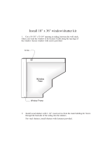
HORIZONTAL INSTALLATION (CONT.)
Step 3. With the adapter and pipe attached to the stove, slide the stove into its correct location, maintaining
minimum clearance to combustibles, and mark the wall for a 10” x 10” (254mm x 254mm) square
hole. The center of the square hole should line up with the centerline of the horizontal pipe, as
shown in Figure 6. Cut and frame the hole in the exterior wall where the vent will be terminated.
If the wall being penetrated is constructed of noncombustible material, i.e. masonry block or
concrete, a 7” (178mm) diameter hole is acceptable.
NOTE:
(1) The horizontal run of vent must be level, or have a ¼” (6mm) rise for every 1’ (305mm) of run
towards the termination. Never allow the vent to run downward. This could cause high temperatures
and may present the possibility of a fire.
(2) The location of the horizontal vent termination on an exterior wall must meet all local and national
building codes, and must not be easily blocked or obstructed.
(3) For installations requiring a vertical rise on the exterior of the building, 14” (356mm) and 36”
(914mm) tall snorkel terminations are available. Follow the same installation procedures as used
for standard horizontal terminations. If the snorkel termination must be installed below grade (i.e.
basement application), proper drainage must be provided to prevent water from entering the
snorkel termination. Do not backfill around snorkel termination.
NOTE:With proper vertical rise, refer to Venting Graph on page 15, up to four, 90 degree elbows may be
used.
Minimum vertical rise in a horizontal venting installation is 2’ (two feet). (See Venting Graph,
page 15.)
CENTER LINE
CENTER
LINE
CENTER OF HOLE
FIG. 6
Note: USE THE FOLLOWING
HORIZONTAL TERMINATION CAPS
ONLY!
1) Simpson DuraVentPart #985
OR
2) Aladdin Hearth Products Part
#HHW2

Page 20
HORIZONTAL INSTALLATION (CONT.)
Step 4. Position the horizontal vent termination in the center of the 10” (254mm) square hole, and attach
to the exterior wall with the four wood screws provided. Before attaching the Vent Termination to
the exterior wall, run a bead of non-hardening mastic around its outside edges, so as to make a
seal between it and the wall. The arrow on the vent cap should be pointing up. Insure that proper
clearances to combustible materials are maintained (Figure 7).
NOTE:
(1) The four wood screws provided should be replaced with appropriate fasteners to stucco, brick,
concrete, or other types of sidings.
(2) For buildings with vinyl siding, a vinyl siding standoff (Simpson Dura-Vent part 950), should be
installed between the vent cap and the exterior wall (Figure 8). Attach the vinyl siding standoff to
the horizontal vent termination. Remove vinyl siding under termination cap. The vinyl siding
standoff prevents excessive heat from possibly melting the vinyl siding material. Vent terminal
shall not be recessed into a wall or siding.
FIG. 8
Remove siding from
beneath Standoff
Part #985
or HHW2
WOOD
SCREW
FIG. 7
/