Page is loading ...

1 7022-514E May 12, 2017
CASTILE PELLET INSERT APPLIANCE
Model(s):
CASTILEI-MBK CASTILEI-PMH
CASTILEI-CSB
Installation and service of this appliance should be performed by
qualified personnel. Hearth & Home Technologies recommends
HHT Factory Trained or NFI certified professionals.
Installation Manual
Installation & Appliance Set-Up
INSTALLER: Leave this manual with party responsible for use and operation.
OWNER: Retain this manual for future reference.
NOTICE: DO NOT DISCARD THIS MANUAL
O-T L
Tested and
Listed by
Portland
Oregon USA
OMNI-Test Laboratories, Inc.
C
US
WARNING
If the information in these instruc-
tions is not followed exactly, a
re could result causing property
damage, personal injury, or death.
• Donotstoreorusegasolineorotheram-
mablevaporsandliquidsinthevicinityof
thisoranyotherappliance.
• Donotoverre-Ifapplianceorchimney
connectorglows,youareoverring.Over
ringwillvoidyourwarranty.
• Complywithallminimumclearancesto
combustiblesasspecied.Failureto
complymaycausehousere.
HOT SURFACES!
Glassandothersurfacesarehot
duringoperationANDcooldown.
Hot glass will cause burns.
• Donottouchglassuntilitiscooled
• NEVERallowchildrentotouchglass
• Keepchildrenaway
• CAREFULLY SUPERVISE children in same room as
replace.
• Alertchildrenandadultstohazardsofhightemperatures
• High temperatures may ignite clothing or other
ammable materials.
• Keep clothing, furniture, draperies and other ammable
materialsaway.
WARNING
CAUTION
Testedandapprovedforwoodpelletsandcornpellets.
Burningofanyothertypeoffuelvoidsyourwarranty.
NOTE
ToobtainaFrenchtranslationofthismanual,pleasecontact
yourdealerorvisitwww.quadrare.com
Pourobtenirunetraductionfrançaisedecemanuel,s’ilvous
plaîtcontactervotrerevendeurouvisitezwww.quadrare.com
CAUTION
Checkbuildingcodespriortoinstallation.
• InstallationMUSTcomplywithlocal,regional,stateandna-
tionalcodesandregulations.
• Consultlocalbuilding,reofcialsorauthoritieshavingjuris-
dictionaboutrestrictions,installationinspection,andpermits.

2 7022-514E May 12, 2017
CASTILE INSERT
TABLE OF CONTENTS
Safety Alert Key:
• DANGER! Indicatesahazardoussituationwhich,ifnotavoidedwillresultindeathorseriousinjury.
• WARNING!Indicatesahazardoussituationwhich,ifnotavoidedcouldresultindeathorseriousinjury.
• CAUTION! Indicatesahazardoussituationwhich,ifnotavoided,couldresultinminorormoderateinjury.
• NOTICE:Indicatespracticeswhichmaycausedamagetotheapplianceortoproperty.
1 Important Safety Information ............3
A.ApplianceCertication......................................................3
B.BTU&EfciencySpecications........................................3
C.GlassSpecications.........................................................3
D.ElectricalRating................................................................3
E.MobileHomeApproved.................................................... 3
2 Getting Started ...................................4
A
.
Design,Installation&LocationConsiderations..........................4
B.ThermostatWallControlLocation......................................5
C.ToolsAndSuppliesNeeded..............................................5
D.InspectApplianceandComponents.................................5
E.InstallChecklist..................................................................6
3 Dimensions and Clearances .............7
A.ApplianceDimensions......................................................7
B.ClearanceToCombustibles,ULandULC.........................9
C.MasonryandZeroClearanceFireplaces.........................10
D.MinimumOpeningforMasonry
andZeroClearanceFireplaces.........................................10
E.InstallationintoaFactory-BuiltFireplace..........................11
F.InstallationintoaMasonryFireplace
..................................12
G.PrefabricatedMetalChimney...........................................12
4 Vent Information ...............................13
A.VentingTerminationMinimumRequirements...................13
B.AvoidingSmokeandOdors...............................................14
C.NegativePressure............................................................15
D.Draft.................................................................................15
E.ChimneyandExhaustConnection..................................15
F.EquivalentFeetofPipe....................................................16
G.PipeSelectionChart........................................................16
H.PelletVentingCharts.........................................................17
5 Venting Systems ..............................18
A.FullRelineWithOutsideAir-Horizontal...........................18
B.FullRelineWithOutsideAir-Vertical..............................19
6 Appliance Set-Up .............................20
A.LevelingSystem...............................................................20
B.OutsideAirKitInstructions................................................20
C.DoorHandleRemoval.......................................................21
D.DoorRemoval...................................................................21
E.AdjustableHearthSupport................................................21
F.HearthSupportforStandardSurroundOnly......................22
G.Surround&TrimSet........................................................23
H.SurroundandCastTrimSet............................................24
I.OptionalLogSetPlacementInstructions............................25
J.ThermostatInstallationandOperation..............................26
7 Mobile Home Installation .................27
8 Reference Materials .........................28
9 Accessory List .................................29

May 12, 2017 7022-514E 3
CASTILE INSERT
Model CastilePelletInsert-B
Laboratory OMNITestLaboratories,Inc.
Report No. 061-S-77d-6.2
Type SolidFuelRoomAppliance/PelletFuel
BurningTypeInsert
Standard ASTME1509-2004,ULCS628-93and
ULC/ORD-C1482-M1990RoomAppli-
ancePelletFuelBurningTypeand(UM)
84-HUD,MobileHomeApproved
FCC ComplieswithPart15ofFCCRules.
Operationissubjecttothefollowing
twoconditions:(1)thisdevicemaynot
causeharmfulinterference,and(2)this
devicemustacceptanyinterference
received,includinginterferencethatmay
causeundesiredoperation.
1 Important Safety Information
NOTE:Hearth&HomeTechnologies,manufacturerof
thisappliance,reservestherighttoalteritsproducts,their
specicationsand/orpricewithoutnotice.
Improper installation, adjustment, alteration, service or
maintenancecancauseinjuryorpropertydamage.
Forassistanceoradditionalinformation,consultaqualied
installer,serviceagencyoryourdealer.
Quadra-FireisaregisteredtrademarkofHearth&Home
Technologies.
• Installationanduseofanydamagedappliance.
• Modicationoftheappliance.
• Installationother than as instructed by Hearth & Home
Technologies.
• Installationand/oruseofanycomponentpartnotapprovedby
Hearth&HomeTechnologies.
• Operatingappliancewithoutfullyassemblingallcomponents.
• Operating appliance without legs attached (if supplied with
appliance).
• DoNOTOverre-Ifapplianceorchimneyconnectorglows,
youareoverring.
Anysuchactionthatmaycausearehazard.
WARNING
Fire Risk.
Hearth&HomeTechnologiesdisclaimsany
responsibilityfor,andthewarrantywillbevoided
by,thefollowingactions:
C. Glass Specications
Thisapplianceisequippedwith5mmceramicglass.
Replaceglassonlywith5mmceramicglass.Pleasecon-
tactyourdealerforreplacementglass.
D. Electrical Rating
115VAC,60Hz,Start4.1Amps,Run1.1Amps
NOTE: Somegeneratororbatteryback-upsystemsmay
notbecompatiblewiththemicro-processorelectronicson
thisappliance.Pleaseconsultthepowersupplymanufac-
turerforcompatiblesystems.
E. Mobile Home Approved
• Thisapplianceisapprovedformobilehomeinstalla-
tionswhennotinstalledinasleepingroomandwhen
anoutsidecombustionairinletisprovided.
• Thestructuralintegrityofthemobilehomeoor,ceil-
ing,andwallsmustbemaintained.
• Theappliancemustbeproperlygroundedtotheframe
of the mobile home and use only Listed pellet vent
Class“L”or“PL”connectorpipe.
• OutsideAirKit,partOAK-ACCmustbeinstalledina
mobilehomeinstallation.
NOTE: Thisinstallationmustconformwithlocalcodes.In
theabsenceoflocalcodesyoumustcomplywiththeASTM
E1509-2004, ULC S628-93, ULC/ORD-C-1482-M1990,
(UM) 84-HUD
A. Appliance Certication
B. BTU & Efciency Specications
TheQuadra-FireCastilePelletInsertmeetstheU.S.Envi-
ronmental ProtectionAgency’s emission limits for pellet
appliancessoldafterMay15,2015.
This pellet insert needs periodic inspection and repair for
properoperation.Itisagainstfederalregulationstooperate
this pellet insert in a manner inconsistent with operating
instructionsinthismanual.
EPACertication#: 940-14
EPACertiedEmissions: 1.8gramsperhour
*LHVTestedEfciency: N/A
**HHVTestedEfciency: N/A
***EPABTUOutput: 8,500to28,200/hr.
****BTUInput: 11,600to38,700/hr.
VentSize: 3or4inches,“L”or“PL”
HopperCapacity: 45lbs.
Fuel WoodPellets
*WeightedaverageLHVefciencyusingdatacollectedduring
EPAemissionstest.
**WeightedaverageHHVefciencyusingdatacollectedduring
EPAemissionstest.
***ArangeofBTUoutputsbasedonEPADefaultEfciencyand
theburnratesfromthelowandhighEPAtests.
****Based on the maximum feed rate per hour multiplied by
approximately 8600 BTU’s which is the average BTU’s froma
poundofpellets.

4 7022-514E May 12, 2017
CASTILE INSERT
Install Guide
2 Getting Started
Marginal Location:
• Below peak
Location NOT recommended:
• Not the highest point of the roof
• Wind loading possible
Multi-level Roofs
Windward
Leeward
Recommended:
Outside Air Intake
on windward side
NOT recommended:
Outside Air Intake
on leeward side
Recommended Location:
• Above peak
Recommended:
• Insulated exterior chase
in cooler climates
Recommended Location:
• Above peak
• Inside heated space
Location NOT recommended:
• Too close to tree
• Below adjacent structure
• Lower roof line
• Avoid outside wall
Marginal Location:
• Wind loading possible
Figure 4.1
A
.
Design, Installation & Location Considerations
1. Appliance Location
NOTICE: Check building codes prior to installation.
• InstallationMUSTcomplywithlocal,regional,stateand
nationalcodesandregulations.
• Consultinsurance carrier, local building inspector, re
ofcialsorauthoritieshavingjurisdictionoverrestrictions,
installationinspectionandpermits.
Itisagoodideatoplanyourinstallationonpaper,usingexact
measurements for clearances and oor protection, before
actuallybeginningtheinstallation.Locationoftheappliance
andchimneywillaffectperformance.
Considerationmustbegivento:
• Safety,convenience,trafcow
• Placementofthechimneyandchimneyconnectorandto
minimizetheuseofchimneyoffsets.
• Placetheappliancewheretherewillbeaclearpassage
foraListedchimneythroughtheceilingandroof(vertical)
orthroughexteriorwall(horizontal).
• Installingtherequiredoutsideairkitwillaffectthelocation
oftheventtermination.
Whenlocatingventandventingtermination,theidealloca-
tionistoventaboverooflinewhenpossible.Thisminimizes
theaffectsofwindloading.
Since pellet exhaust can contain ash,soot orsparks, you
mustconsiderthelocationof:
• Windows
• AirIntakes
• AirConditioner
• Overhang,softs,porchroofs,adjacentwalls
• Landscaping,vegetation
• Horizontalorverticalventtermination
2. Floor Support
The supporting oor under the appliance must be able to
handletheweightoftheappliance,fuelloadandtheweight
ofthechimney.
Ensure that your oor will support these weights prior to
installation. Add sufcient additional support to meet this
weightrequirement prior to installation. Theweight of the
applianceis252lbs.
CAUTION
Ifburningshelledeldcorn,youmustuseapprovedventingspecif-
icallydesignedforcorntopreventcorrosionordegradation.Follow
theinstructionsfromtheventingmanufacturer.

May 12, 2017 7022-514E 5
CASTILE INSERT
•Installationanduseofanydamagedappliance.
•Modicationoftheappliance.
• Installation other than as instructed by Hearth & Home
Technologies.
• Installationand/oruseofanycomponentpartnotapproved
byHearth&HomeTechnologies.
• Operatingappliancewithoutfullyassemblingallcomponents.
• Operatingappliance withoutlegsattached (ifsupplied with
appliance).
• DoNOTOverre
Or any such action that may cause a re hazard.
WARNING
Hearth&HomeTechnologiesdisclaimsany
responsibilityfor,andthewarrantywillbevoidedby,
thefollowingactions:
ReciprocatingSaw ChannelLocks
Hammer PhillipsScrewdriver
TapeMeasure PlumbLine
1/4”Self-TappingScrews FramingMaterial
Hi-tempCaulkingMaterial Gloves
SafetyGlasses FramingSquare
ElectricDrill&Bits(1/4”) Level
Mayalsoneed:
VentSupportStraps VentingPaint
Tools and building supplies normally required
for installation, unless installing into an existing
masonry replace:
C. Tools And Supplies Needed
B. Thermostat Wall Control Location
The thermostatwallcontrol’slocationwillhavesomeaffect
on the appliance’soperation.
• Maximumwirelengthfromapplianceis100feet(30.48m)
continuousnon-splicedwire.Recommended20gauge
wire,solidcopper.
• When located close to the appliance, it may require a
slightlyhighertemperaturesettingtokeeptherestofthe
housecomfortable.
• Whenlocatedinanadjacentroomoronadifferentoor
level,youwillnoticehighertemperatures near the appli-
ance.
D. Inspect Appliance and Components
• Opentheapplianceandremoveallthepartsandarticles
packedinsidetheComponentPack.Inspectalltheparts
andglassforshippingdamage.
• Reporttoyourdealeranypartsdamagedinshipment.
•
Alllabelshavebeenremovedfromtheglassdoor.
•
Platedsurfaceshavebeenwipedcleanwithasoftcloth,
ifapplicable.
• Read all the instructions before starting the installation.
Follow these instructions carefully during the
installation to ensure maximum safety and benet.
• Follow pipe manufacturer instructions for installation
and air clearance requirements.
WARNING
Fire Risk.
Damagedpartscouldimpairsafeoperation.DoNOT
install damaged, incomplete or substitute compo-
nents.

6 7022-514E May 12, 2017
CASTILE INSERT
E. Install Checklist
Appliance Install
Appliance is leveled and connector is secured to appliance.
Hearth extension size/height decided.
Outside air kit installed.
Floor protection requirements have been met.
If appliance is connected to a masonry chimney, it should be cleaned and
inspected by a professional. If installed to a factory built metal chimney, the
chimney must be installed according to the manufacturer’s instructions and
clearances.
Chimney
Chimney installed, locked and secured in place with proper clearance.
Chimney meets recommended height requirements (14-16 feet).
Terminations installed and sealed.
Clearances
Combustible materials not installed in non-combustible areas.
Mantels and wall projections comply with installation manual requirements.
Protective hearth strips and hearth extension installed per manual requirements.
Appliance Setup
All packaging and protective materials removed.
All labels have been removed from the door.
All packaging materials are removed from inside/under the appliance.
Manual bag and all of its contents are removed from inside/under the appliance
and given to the party responsible for use and operation.
ATTENTION INSTALLER:
Follow this Standard Work Checklist
This standard work checklist is to be used by the installer in conjunction with, not instead of, the instructions contained in this installation manual.
Customer: __________________________________________________________________________
Date Installed: __________________________________________________________________________
Lot/Address: __________________________________________________________________________
Location of Appliance: ______________________________________________________________
Installer: __________________________________________________________________________
Dealer/ Distributor Phone #: ______________________________________________________________
Serial #: __________________________________________________________________________
Model : __________________________________________________________________________
WARNING! Risk of Fire or Explosion!
Hearth & Home Technologies recommends the following:
• That this checklist remain visible at all times on the appliance until the installation is complete.
Comments: Further description of the issues, who is responsible (Installer/Builder/Other Trades, etc.) and corrective action needed:
Comments communicated to party responsible by on
(Builder/Gen. Contractor) (Installer) (Date)
YES IF NO, WHY?

May 12, 2017 7022-514E 7
CASTILE INSERT
Figure 7.2- Front View with Small Surround and Cast
Panel Set
Figure 7.1 - Top View with Cast Panel Set
27-3/4 in (706mm)27-3/4 in (706mm)
23-3/8 in (594mm)
23-3/8 in (594mm)
12-7/8 in
(328mm)
12-7/8 in
(328mm)
10-7/8 in
(278mm)
10-7/8 in
(278mm)
32-3/8 in (822mm)
32-3/8 in (822mm)
8 in
(203mm)
8 in
(203mm)
10-3/8 in
(264mm)
9-1/2 in
(240)
9-1/2 in
(240)
16 in (407)
16 in (407)
42-1/2 in (1080)
42-1/2 in (1080)
30 in
(761)
30 in
(761)
27-7/8 in (708mm)27-7/8 in (708mm)
23-3/8 in (594mm)
23-3/8 in (594mm)
13-1/8 in
(333mm)
13-1/8 in
(333mm)
11 in
(280mm)
11 in
(280mm)
32-3/8 in (822mm)
32-3/8 in (822mm)
10-1/4 in
(262mm)
10-1/4 in
(262mm)
8 in
(203mm)
8 in
(203mm)
Figure 7.3 - Top View with Small Surround Panel Set
Figure 7.4- Front View with Small Surround Panel Set
3 Dimensions and Clearances
A. Appliance Dimensions
9-1/2 in
(240mm)
9-1/2 in
(240mm)
16 in (407mm)
16 in (407mm)
43 in (1092mm)
43 in (1092mm)
31 in
(787mm)
31 in
(787mm)

8 7022-514E May 12, 2017
CASTILE INSERT
Figure 8.2- Front View with Large Surround and Cast
Panel Set
Figure 8.4- Front View with Large Surround Panel Set
9-1/2 in
(240)
9-1/2 in
(240)
16 in (407)
16 in (407)
48 in (1219)
48 in (1219)
34 in
(863)
34 in
(863)
Figure 8.1 -Side View with Small or Large Surround and
Cast Panel Set
9-3/4 in
(249)
9-3/4 in
(249)
22-3/4 in (579)
22-3/4 in (579)
11-3/8 in
(290)
11-3/8 in
(290)
21 in
(533)
21 in
(533)
2 in (51)
2 in (51)
25-1/4 in
(643)
25-1/4 in
(643)
9-3/4 in
(247mm)
9-3/4 in
(247mm)
22-3/4 in (579mm)
22-3/4 in (579mm)
11-3/8 in
(290mm)
11-3/8 in
(290mm)
21 in
(533mm)
21 in
(533mm)
2 in (51mm)
2 in (51mm)
25-1/4 in
(643mm)
25-1/4 in
(643mm)
Figure 8.3 -Side View with Small or Large Surround
Panel Set
A. Appliance Dimensions (continued)
9-1/2 in
(240mm)
9-1/2 in
(240mm)
16 in (407mm)
16 in (407mm)
51 in (1295mm)
51 in (1295mm)
34 in
(862mm)
34 in
(862mm)

May 12, 2017 7022-514E 9
CASTILE INSERT
B. Clearance To Combustibles, UL and ULC
Figure 9.1
AS A BUILT-IN - FRAMING DIMENSIONS
Be sure to follow vent manufacturers
clearance to combustibles.
*If interior of chase will be drywalled,
add the thickness to this measurement.
23 in - top vent
(584mm)
23-1/2 in - rear vent
(597mm)
23 in - top vent
(584mm)
23-1/2 in - rear vent
(597mm)
31-7/8 in.
(810mm)
16-7/8 in.*
(429mm)
NOTE:
• IllustrationsreecttypicalinstallationsandareFOR
DESIGNPURPOSESONLY.
•Illustrations/diagramsarenotdrawntoscale.
• Actualinstallationmayvaryduetoindividualdesign
preference.
FireRisk.
Complywithallminimumclearancestocombusti-
blesasspecied.
WARNING
Failuretocomplymaycausehousere.

10 7022-514E May 12, 2017
CASTILE INSERT
C
D
A
B
D. Minimum Opening for Masonry and Zero
Clearance Fireplaces
Figure 10.1
C. Masonry and Zero Clearance Fireplaces
Figure 10.2
NOTE
Itisnecessarytopermanentlysealanyopeningbetween
themasonryofthereplaceandthefacingmasonry.
SIDE TRIM
SIDE WALL
TOP TRIM
25-1/2
(648mm)
31-1/2
(800mm)
HEARTH
EXTENSION
13.5
(343mm)
29-3/4
(1010mm)
Location Inches Millimeters
A Height 21-1/4 540
B
FrontWidth(Steel Panel Set) 28-1/8 714
FrontWidth(Cast Panel Set) 28 711
C RearWidth 23-5/8 600
D
Depth(Steel Panel Set) 13-3/8 340
Depth(Cast Panel Set) 13-1/8 333
FIREPLACE FRONT SURFACE
MANTEL
USA 14in
CANADA 14 (356mm)
37in
(940mm)
12in
max *
Figure 10.3

May 12, 2017 7022-514E 11
CASTILE INSERT
Mark area of
floor to cut
Starter hole
Use 2 x 4 from insert
packaging to support insert
E. Installation into a Factory-Built Fireplace
Thefollowingmodicationsarepermissible:
• Removalofdamperorlockedinopenposition
• Removalofsmokeshelforbafe
• Removalofembercatches
• Removalofregrate
• Removalofviewscreen/curtain
• Removalofdoors
• Removaloffactory-builtreplaceoor
• Externaltrimpieceswhichdonotaffecttheoperationof
thereplacemayberemovedprovidingtheycanbestored
onor within thereplaceforreassembly iftheinsertis
removed.
• The permanent metal warning label provided must be
attached to the back of the replace, with screws or
nails,statingthatthereplacemayhavebeenalteredto
accommodatetheinsert,andmustbereturnedtooriginal
conditionforuseasaconventionalreplace.Figure 10.1
Figure 11.2. Measure and mark the metal
oorforcutting.Withadrill,makeastarter
holeineachcorner.
Figure 11.3. Using a saws-all, cut out the
oor.
Figure 11.4. If the oor is made of thin
metal,werecommendusingthe2x4from
the insert packaging to support the insert.
The2x4mayneedtobecuttotheappro-
priatesize.
250-2061
WARNING
THIS FIREPLACE MAY HAVE BEEN ALTERED
TO ACCOMMODATE AN INSERT. IT MUST BE
RETURNED TO ITS ORIGINAL CONDITION
BEFORE USE AS A SOLID FUEL BURNING
FIREPLACE.
250-2061
Heath & Home Technologies
250-2061
5.5 in. width x 2 in. height
NON. ANOD. ALUM BLACK LETTERS ON SILVER
with 1/8 in. holes on both sides.
Black letters
Figure 11.1
• Ifthehearthextensionislowerthanthereplaceopening,
theportionoftheinsertextendingontothehearthmustbe
supported.
• Manufacturer designed adjustable support kit can be
orderedfromyourdealer.
NOTE: Refer to chimney liner manufacturer for recom-
mendations on supporting the liner. Installation
into replaces without a permit will void the listing.•
• The rebrick (refractory), glass doors, screen rails,
screenmeshandloggratescanberemovedfromafac-
tory-builtreboxinordertogainminimuminsertopen-
ingrequirements.
• Anysmokeshelves,shieldsandbafesmayberemoved
fromafactory-builtrebox ifattachedwithmechanical
fasteners.
• The metal oor of the factory-built rebox may be
removed to facilitate the installation of the insert only
whena1inch(25mm)airspaceisprovidedbetweenthe
insertandtheoorofouterwrap.
Thefollowingisonlyoneexampleastherearemanydiffer-
entmodelsoffactory-builtreplaces.
NOTE: This example is for reference only. Any modica-
tions must not compromise the structural integrity
or reduce the protection for combustible materials.

12 7022-514E May 12, 2017
CASTILE INSERT
Keep sharp edge of
metal floor away from
power cord
Leveling Leg
Figure 12.1.Placetheinsertintothefacto-
ry-builtrebox.Ensurethatthepowercord
can not be damaged by the sharp metal
edge.Youmayneedtocutoutanotchto
accommodatethecord.
Figure 12.2.Ensurethatthelevelinglegis
positionedoverthe2x4beforelevelingthe
insert.Minimum1”clearance.
NOTICE: InCanadawhenusingafactory-builtchim-
neyitmustbesafetylisted, Type UL103 HT (2100
o
F)
[1149
o
C] CLASS “A” orconformingtoCAN/ULC-
S629M, STANDARD FOR 650
o
C FACTORY-BUILT
CHIMNEYS.
G. Prefabricated Metal Chimney
Thechimneycanbeneworexisting,masonryorprefabricated
andmustmeetthefollowingminimumrequirements:
•Must be minimum 6 inch (152mm) inside diameter of
hightemperaturechimneylistedtoUL103HT(2100
o
F)
orULC-S628.
•Mustusecomponentsrequiredbythemanufacturerfor
installation.
•Mustmaintainclearancesrequiredbythemanufacturer
forinstallation.
•Refertomanufacturersinstructionsforinstallation
•This insert islistedtoASTM E 1509-12 Standardand
isapproved for installation intolisted factory-builtzero
clearance replaces listed to UL 127 conforming to the
followingspecicationsandinstructions:
•The original factory-built clearance replace chimney
cap must be re-installed after installing the approved
chimney liner meeting type UL 103 HT requirements
(2100°F)perUL1777.
•IfthechimneyisnotlistedasmeetingHTrequirements,
orifthefactorybuiltreplacewastestedpriorto1998,a
fullheightlistedchimneylinermustbeinstalledfromthe
applianceuecollartothechimneytop.
•Thelinermustbesecurelyattachedtotheinsertuecollar
andthechimneytop.
•Theairowofthefactory-builtzero-clearancereplace
systemmustnotbealtered.The ue liner topsupport
attachmentmustnotreducetheairowfortheexisting
air-cooledchimneysystem.
•Nodilutionairisallowedtoenterthechimney.
1.Securethereplacedamperintheopenposition.If
thiscannotbeaccomplished,itwillbenecessaryto
removethedamper
2.Seal damper area of chimney around chimney
connector with a high temperature sealant orseal
insertagainstthefaceofthereplace.
3.Bothmethodsmustberemovableandreplaceable
forcleaningandre-installation.
• Removingoorofreplacemustnotweakenstructure
ofreboxorreduceprotectionforcombustiblematerials.
• Finalapprovalofthisinstallationtypeiscontingentupon
theappropriatelocalauthorityhavingjurisdiction.
WARNING
F. Installation into a Masonry Fireplace
Allmodicationsthatcan be made to a Factory BuiltFire-
placecanbemadetoaMasonryFireplace.
In addition DO NOT remove any brick or mortar from the
existingreplace.
Risk of Fire!
Follow venting manufacturer’s clearances and
instructionswheninstallingventingsystem.
WARNING
1”
Example Removal of Factory-Built Fireplace Cont.

May 12, 2017 7022-514E 13
CASTILE INSERT
4 Vent Information
A. Venting Termination Minimum Requirements
J or K
X
V
M
I
H
A
V
G
B
V
V
A
B
V
F
V
C
B
B
E
L
V
D
V
Electrical
Service
V
N
V
N
V
N
N
V
Inside Corner
FIXED
CLOSED
OPEN
OPEN
FIXED
CLOSED
V
X
G
G
Termination Cap
Air Supply Inlet
Gas Meter
Restricted Area
O
P
Figure 13.1
A 12in. AboveFinishGrade(thegradesurface
mustbeanon-combustiblematerial
B 48in.noOAK Opendoororwindow:belowortotheside
B 12in. Opendoororwindow:above
C 6in. Permanentlyclosedwindow:above,below
ortotheside
D 36in.noOAK Verticalclearancetoaventilatedsoft
locatedabovetheterminalwithinahori-
zontaldistanceof2ftfromthecenter-line
oftheterminal
E 12in. Clearancetounventilatedsoft
F 12in. Clearancetooutsidecorner
G 12in. Clearancetoinsidecorner
H 36in. Abovegasmeter/regulatormeasuredfrom
horizontalcenter-lineofregulator
I 36in.USA
72in.Canada
Clearancetoserviceregulatorventoutlet
J 12in.
48in.noOAK
Clearancetonon-mechanicalairsupply
inlettothebuildingorthecombustionsair
inlettoanyotherappliance
K 10fthorizontal
3ftvertical
Clearancetomechanicalairsupply
L 7ft. Abovepavedsidewalk,paveddriveway
locatedonpublicproperty
M 12in. Underanopenveranda,porch,deckor
balcony
N SeeNote
below*
Electricservice:above,belowortothe
side(locationmustnotobstructorinterfere
withaccess)
O 24in. Adjacentbuilding,fencesandprotruding
partsofthestructure
P 12in. Clearanceaboverooflineforvertical
terminations
All minimum clearances are listed with an Outside Air Kit (OAK) installed, unless otherwise noted in table below.
24in. Abovegrass,topofplants,woodoranyothercom-
bustible
36in.noOAK Clearancefromanyforcedairintakeofotherappli-
ance
12in. Clearancehorizontallyfromcombustiblewall
15in. Venteddirectlythroughawall,minimumlengthof
horizontalpipe
6in.horizontal
12in.vertical
Minimumhorizontalorverticalterminationsmust
protrudefromwall
*NOTE: Consultlocalbuilding,reofcialsorauthoritieshavingjurisdic-
tion.Localcodesorregulationsmayrequiredifferentclearances.
NOTICE:
Do NOT Terminate Vent:
• Inanylocationthatwillallowuegasesorsootfromen-
teringorstainingthebuilding
• Inanylocationwhichcouldcreateanuisanceorhazard
• Inanyenclosedorsemi-enclosedareasuchasacarport,
garage, attic, crawl space,under a sun deck or porch,
narrowwalkway
• Closely fenced area, or any location that can build up
a concentration of fumes such as a stairwell, covered
breezeway,etc.
NOTICE:
Termination must exhaust above air inlet elevation.
• Itisrecommendedthatatleast60inches(1.52m)ofvertical
pipebeinstalledwhenapplianceisventeddirectlythrougha
wall.Thiswillcreateanaturaldraft,whichwillhelpprevent
thepossibilityofsmokeorodorventingintothehomeduring
apoweroutage.
• Itwillalsokeepexhaustfromcausinganuisanceorhazard
byexposingpeopleorshrubstohightemperatures.
• Thesafestandpreferredventingmethodistoextendthevent
verticallythroughtherooforabovetheroof.

14 7022-514E May 12, 2017
CASTILE INSERT
B. Avoiding Smoke and Odors
Negative Pressure, Shut-Down and Electrical Power
Failure
To reduce the probability of back-drafting or burn-back in
thepelletapplianceduringpowerfailureorshutdowncon-
ditions, it must be able to draft naturally without exhaust
bloweroperation.
Negativepressureinthehousewillresistthisnaturaldraftif
notaccountedforinthepelletapplianceinstallation.
Heatrisesinthehouseandleaksoutatupperlevels.This
airmustbereplacedwithcoldairfromoutdoorswhichows
intolowerlevelsofthehouse.
Ventsandchimneysintobasementsandlowerlevelsofthe
house can become the conduit for air supply and reverse
undertheseconditions.
Outside Air
Anoutsideairkitisrecommendedin allinstallations.The
OutsideAirKitmustbeorderedseparately.
Pernationalbuildingcodes,considerationmustbegivento
combustionairsupplytoallcombustionappliances.Failure
tosupplyadequatecombustionairforallappliancedemands
mayleadtobackdraftingofthoseandotherappliances.
Whentheapplianceisroofvented(stronglyrecommended):
Theairintakeisbestlocatedontheexteriorwalloriented
towardstheprevailingwinddirectionduringtheheating
season.
Whentheapplianceisside-wallvented:
Theairintakeisbestlocatedonthesameexteriorwallas
theexhaustventoutletandlocatedloweronthewallthan
theexhaustventoutlet.
Theoutsideairsupplykitcansupplymostofthedemandsof
thepelletappliance,butconsiderationmustbegiventothe
totalhousedemand.
Housedemandmayconsumetheairneededfortheappli-
ance.Itmaybenecessary toaddadditionalventilationto
thespaceinwhichthepelletapplianceislocated.
ConsultwithyourlocalHVACprofessionaltodeterminethe
ventilationdemandsforyourhouse.
Vent Congurations
To reduce probability of reverse drafting during shut-down
conditions Hearth & Home Technologies strongly recom-
mends:
• Installingthepelletventwithaminimumverticalrunof
5feet(1.52m).Preferablyterminatingabovetheroof
line.
• Installingtheoutsideairkitatleast4feet(1.22m)below
theventtermination.
Topreventsootdamagetoexteriorwallsofthehouseandto
preventre-entryofsootorashintothehouse:
• Maintain specied clearances to windows, doors and
airinlets,includingairconditioners.
• Vents should not be placed below ventilated softs.
Runtheventabovetheroof.
• Avoidventingintoalcovelocations.
• Ventsshouldnotterminateunderoverhangs,decksor
ontocoveredporches.
• Maintain minimum clearance of 12 inches (305mm)
from the vent termination to the exterior wall. If you
seedepositsdevelopingonthewall,youmayneedto
extendthisdistancetoaccommodateyourinstallation
conditions.
CAUTION
• DONOTCONNECTTHISApplianceTOACHIMNEYFLUE
SERVICINGANOTHERAPPLIANCE.
• DONOTCONNECTTOANYAIRDISTRIBUTIONDUCT
ORSYSTEM.
Hearth&HomeTechnologiesassumesnoresponsibili-
tyfor,notdoesthewarrantyextendto,smokedamage
causedbyreversedraftingofpelletappliancesundershut
downorpowerfailureconditions.

May 12, 2017 7022-514E 15
CASTILE INSERT
C. Negative Pressure
Negative pressure results from the imbalance of air avail-
ablefortheappliancetooperateproperly.Itcanbestrongest
inlowerlevelsofthehouse.
Causesinclude:
• Exhaustfans(kitchen,bath,etc.)
• Rangehoods
• Combustion air requirements for furnaces, water
appliancesandothercombustionappliances
• Clothesdryers
• Locationofreturn-airventstofurnaceorairconditioning
• ImbalancesoftheHVACairhandlingsystem
• Upperlevelairleakssuchas:
- Recessedlighting
- Attichatch
- Ductleaks
Tominimizetheeffectsofnegativeairpressure:
• Installtheoutsideairkitwiththeintakefacingprevailing
windsduringtheheatingseason
• Ensureadequateoutdoorairforallcombustionappliances
andexhaustequipment
• Ensurefurnaceandairconditioningreturnventsarenot
locatedintheimmediatevicinityoftheappliance
• Avoid installing the appliance near doors, walkways or
smallisolatedspaces
• Recessedlightingshouldbea“sealedcan”design
• Attichatchesweatherstrippedorsealed
• Atticmountedductworkandairhandlerjointsandseams
tapedorsealed
D. Draft
Draftisthepressuredifferenceneededtoventanappli-
ancesuccessfully.Whenanapplianceisdraftingsuc-
cessfully,allcombustionbyproductsareexitingthehome
throughthechimney.
Installthroughthewarmairspaceenclosedbythebuild-
ingenvelope.Thishelpstoproducemoredraft,especially
duringlightinganddie-downofthere.
Considerationsforsuccessfuldraftinclude:
• Preventingnegativepressure
• Locationofapplianceandchimney
NOTICE: Hearth & Home Technologies assumes no
responsibility for the improper performance of the chimney
system caused by:
• Inadequate draft due to environmental conditions
• Down drafts
• Tight sealing construction of the structure
• Mechanical exhausting devices
E. Chimney and Exhaust Connection
1. Chimney & Connector:Use3or4inch(76-102mm)diameter
type“L”or“PL”ventingsystem.Itcanbeventedverticallyor
horizontally.
2. Mobile Home: ApprovedforallListedpelletvent.Ifusingthe
3inch(76mm)verticalTopVentAdapterKitorthe3to6inch
(76-152mm) Top Vent OffsetAdapter, use Listed double wall
ueconnector.AQuadra-FireOutsideAirKitmustbeusedwith
manufacturedhomeinstallations.
3. Residential: The3inch(76mm)verticalTopVentAdapterKitand
the3to6inch(76-152mm)TopVentOffsetAdapteraretested
touse24gaugesinglewallueconnectororListeddoublewall
ue connector to ClassA Listed metalchimneys, or masonry
chimneysmeetingInternationalResidentialCodestandardsfor
solidfuelappliances.
4. INSTALL VENT AT CLEARANCES SPECIFIED BY THE
VENT MANUFACTURER.
5. Secure exhaust venting system to the appliancewith at least
3screws.Alsosecureallconnectorpipejointswithatleast3
screwsthrougheachjoint.
6. DONOTINSTALLAFLUEDAMPERINTHEEXHAUSTVENT-
INGSYSTEMOFTHISAppliance.
7. DO NOT CONNECT THISAppliance TOA CHIMNEYFLUE
SERVINGANOTHERAPPLIANCE.
NOTE: All pipe must be welded seam pipe whenever possible.
Seal pipe joints with high temperature silicone (500°F [260°C]
minimum rated only).
NOTE: If burning shelled eld corn, you must use approved
venting specically designed for corn. Follow the instructions
from the venting manufacturer.
WARNING
Risk of Asphyxiation!
Negativepressurecancausespillageofcombustion
fumesandsoot.

16 7022-514E May 12, 2017
CASTILE INSERT
Fire Risk.
• OnlyLISTEDventingcomponentsmaybeused.
• NOOTHERventcomponentsmaybeused.
• Substituteordamagedventcomponentsmay
impairsafeoperation.
WARNING
RISK OF INJURY OR PROPERTY DAMAGE!
•Improperinstallation,adjustment,alteration,service
ormaintenancecancauseinjuryorpropertydamage.
•Refertotheowner’sinformationmanualprovided
withthisappliance.
• Forassistanceoradditionalinformationconsultaqualied
installer,serviceagencyoryourdealer.
WARNING
F. E quivalent Feet of Pipe
Thetablebelowcanhelpyoucalculatetheequivalentfeetof
pipewhich6isamethodusedtodeterminepelletventsize.
Figure 16.1.
2ft.
2ft.
3ft.
2ft.
Example of 3 Elbow-Rear Vent Termination Calculation
Pellet Venting
Component
# of
Elbows
Feet of
Pipe
Multiplied
By
Equivalent
Feet
Components
Equivalent Feet
90
o
ElboworTee
3 X 5 15
45
o
Elbow
X 3
HorizontalPipe
7 X 1 7
VerticalPipe
2 X 0.5 1
Total Equivalent Feet 23
Note:Thisisagenericexampleandisnot
intendedtorepresentanyspecicfueltype.
VentsurfacesgetHOT,cancauseburnsif
touched.Non-combustibleshieldingorguards
mayberequired.
WARNING
Figure 16.2
3 in. or 4 in. (76mm or 102mm) Diameter Pipe
Equivalent Pipe
Length In Feet
ALTITUDE IN THOUSANDS OF FEET
0
20
30
1 2 3 4 5 6 7 8 9 10
4 in. (102mm) Diameter Pipe Only
10
Example 1
Example 2
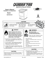
Example 1:Iftheequivalentlengthofpipeis23feet(7m)with
altitudeof8,000feet(2438m)youmustuse4inch(102mm)
diametertype“L”or“PL”vent.
Example 2:Iftheequivalentlengthofpipeis12feet(3.7m)
withaltitudeof6,000feet(1829m)youmayuse3or4inch
(76to102mm)diametertype“L”or“PL”vent.
G. Pipe Selection Chart
Thechartwillhelpyouindeterminingproperventingsize
accordingtotheequivalentfeetofpipecalculatedpreviously
andthealtitudeabovesealevelofthisinstallation.
Figure 16.2.
a. Locatethecalculatedequivalentfeetofpipeonthevertical
leftsideofthechart.
b. Movetotherighthorizontallyonthechartuntilyoureach
youraltitudeabovesealevel.
c. If you fall below the diagonal line, 3 or 4 inch (76 to
102mm)pipemaybeused.
d. Ifitisanywhereabovethediagonalline,a4inch(102mm)
diameterpipeisrequired.
NOTICE:
• A90°elbowis5timesasrestrictivetotheowofexhaust
gasesunderpositivepressureas1foot(305mm)ofhori-
zontalpipe.
• Afootofhorizontalpipeistwiceasrestrictiveasafootof
verticalpipe.
Figure 16.1

May 12, 2017 7022-514E 17
CASTILE INSERT
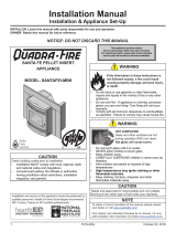
H. Pellet Venting Charts
Themaximumhorizontalventingallowedwithnoverticalvent-
ingattached is 48 inches (1219mm) including one 90° elbow
ortwo45°elbows.Thisisourrecommendedhorizontalvent-
inginstallation. Addition ofanyhorizontal venting beyond48
inches (1219mm) Hearth & Home Technologies strongly rec-
ommendsaminimumof60inches(1524mm)ofadditionalverti-
calvent.Horizontalsectionsofventpipeshouldhavea1/4inch
(6.35mm)riseperfoot.
Hearth & Home Technologies recommends any installation
requiringmorethantwo90°elbows,ormorethan15feet(4.5m)
ofventingtouse4inch(102mm)vent.
Figure 17.1
Fire Risk.
• OnlyLISTEDventingcomponentsmaybeused.
• NO OTHER vent components may be used.
Substituteordamagedventcomponentsmayimpair
safeoperation.
WARNING
NOTICE: Theseareguidelinesforsuccessfulventingofyourpelletappliance.Themoreverticalriseyoucanobtainin
yoursystem,thebetteritwillperform.Horizontalventrunscanaccumulateashandwillneedtobecleanedmoreoften.
Trytokeepthemasshortaspossible.
ONE 90º ELBOW
Total Minimum
Vertical
Vent
Diameter
4 0 3
5 5 3
6 6 3
7 7 3
8 8 4
9 9 4
10 10 4
11 11 4
TWO 90º ELBOWS
Total Minimum
Vertical
Vent
Diameter
2 5 3
3 6 3
4 7 3
5 8 3
6 9 3
THREE 90º ELBOWS
Total Minimum
Vertical
Vent
Diameter
2 11 4
3 12 4
45°elbowisequivalentto1footofstraightpipe
90°elbowisequivalentto3feetofstraightpipe
Minimum Vertical Vent for One Elbow
0
5
10
15
20
0 5 10 15 20
Horizontal Run, (ft)
Minimum Vertical Rise
(ft)
Minimum Vertical Vent for One Elbow
Figure 17.3
Minimum Vertical Vent for Three Elbows
0
5
10
15
20
25
0 2 4 6 8 10 12
Length of Horizontal Sections (ft)
Minimum Vertical Rise
(ft)
Minimum Vertical Vent for Three Elbows
Figure 17.2
Minimum Vertical Vent for Two Elbows
0
5
10
15
20
0 5 10 15
Length of Horizontal Sections, (ft)
Minimum Vertical
Rise, (ft)
Minimum Vertical Vent for Two Elbows

18 7022-514E May 12, 2017
CASTILE INSERT
NOTE:InCanada,wherepassagethroughawallorpartitionof
combustibleconstructionisdesired,theinstallationshallconform
toCAN/CSA-B365.
Fire Risk.
InspectionofChimney:
• Masonrychimneymustbeingoodcondition.
• MeetsminimumstandardofNFPA211
•
Factory-builtchimneymustbeaminimum6inch
(152mm)UL103HT.
WARNING
CAUTION
Neverdrawoutsidecombustionairfrom:
• Wall,oororceilingcavity
• Enclosedspacesuchasanatticorgarage
NOTE:
• IllustrationsreecttypicalinstallationsandareFORDESIGN
PURPOSESONLY.
•Illustrations/diagramsarenotdrawntoscale.
• Actualinstallationmayvaryduetoindividualdesign
preference.
Figure 18.1
Outside Air through Rear
Wall (Horizontal)
NOTE; Use metal plate around
exhaust vent pipe and seal all
edges with non-flammable insu
-
lation such as , mineral wool or
ceramic.
Do not use high temperature
caulking materials to seal any
edge to prevent future service
-
abilit
y.
5 Venting Systems
A. Full Reline With Outside Air - Horizontal

May 12, 2017 7022-514E 19
CASTILE INSERT
B. Full Reline With Outside Air - Vertical
Figure 19.1
NOTE: Checkclearancescarefullyforthistypeofinstal-
lationtoensureadequateroomforoutsideairventing.
Checkbuildingcodespriortoinstallation.
• Installation MUST comply with local, regional, state and
nationalcodesandregulations.
• Consultlocalbuilding,reofcialsorauthoritieshavingjuris-
dictionaboutrestrictions,installationinspection,andpermits.
CAUTION
NOTE: InCanada,onlyafullrelineisallowedperULC
S628-93,ORDULCC1482-M1990.
NOTE: InCanadathisreplaceinsertmustbeinstalled
withacontinuous chimneylinerextendingfromthe re-
placeinserttothetopofthechimney.Thechimneyliner
mustconformtotheClass3requirementsofCAN/ULC-
S635,StandardforLiningSystemsforExistingMasonry
orFactory-BuiltChimneysandVents,orCAN/ULC-S640,
StandardforLiningSystemsforNewMasonryChimneys.
Outside Air
Termination
at
Chimney Top
12” (305mm)
min. below
12” (305mm)
min. above
NOTE; Use metal
plate around
exhaust vent pipe
and seal all edges
with non-flammable
insulation such as
mineral wool or
ceramic.
Do not use high
temperature caulk
-
ing materials to seal
any edge to prevent
future serviceability

20 7022-514E May 12, 2017
CASTILE INSERT
6 Appliance Set-Up
A. Leveling System
Thelevelingboltsarelocatedattherearoftheappliance.
Toaccessthebolts,removethesideaccesspanels.Reach
inandturnthebolttothedesiredheighttoleveltheappli-
ance.ShowninFigures 20.1 and 20.2.
B. Outside Air Kit Instructions
Parts Included in Kit:1pieceof2inchx3ft.exhose,2
hoseclamps,1collarassembly,1terminationcapassem-
bly,1trimring,fasteners.
Tools Needed:Phillipsheadscrewdriver;wirecutters;hole
saworjigsaw.
1. Measuredistancefromoortoairventopeninginappli-
anceandmarklocationonwall.
2. Use saw to cut opening in wall. Cut a 2-1/2 to 3 inch
(64-76mm)openingoninsidewallanda3to3-1/2inch
(76-89mm)openingonoutsideofhouse.
3. Usehoseclamptosecureexpipetocollarassembly.
4. Slidetrimringoverexpipeandrunpipethroughwall.
5. Attachhosetooutsideterminationcapwithsecondhose
clamp.
6. Secureterminationcaptooutsidesurface.
7. Securetrimringtointeriorwall.
CAUTION
Neverdrawoutsidecombustionairfrom:
• Wall,oororceilingcavity
• Enclosedspacesuchasanatticorgarage
Figure 20.1
Figure 20.2
Leveling Bolt on each Side
2 inch diameter Flex Pipe
Attach Termination
Cap to Exterior W
all
Leveling Bolt
/