Page is loading ...

CG-SVU007C-GB
Tracer CH535 Chiller Controller
on models CGAX/CXAX
User Guide
Original instructions

Table of Contents
CG-SVU007C-GB
2 © 2016 Trane
4 UNT-PRC002-GB
Technical Data
FWD 08 12 20 30 45
Power supply (V/Ph/Hz) 230/1/50
Capacities
Cooling capacity on water (1) (kW) 5,2 8,3 15 18,8 30,1
Heating capacity on water (2) (kW) 6,3 11,9 18,9 20,9 38,2
Fan motor (type) 2 x direct drive centrifugal
Fan power input (3) (kW) 0,23 0,46 0,65 1,04 1,51
Current amps (3) (A) 1,1 2,2 3,1 4,7 5,5
Start-up amps (A) 3,2 5,5 9,3 14,1 16,5
Air flow
minimum (m
3
/h) 490 980 1400 1800 2700
nominal (m
3
/h) 820 1650 2300 3000 4500
maximum (m
3
/h) 980 1970 2600 3600 5400
Main coil
Water entering/leaving connections (type) ISO R7 rotating female
(Dia) 3/4" 3/4" 1 1/2" 1 1/2" 1 1/2"
Electric heater (accessory for blower only)
Electric power supply (V/Ph/Hz) 230/1/50 230/1/50 or 400/3/50 400/3/50 400/3/50 400/3/50
Heating capacity (kW) 2/4 8 10 12 12
Hot water coil (accessory for blower only)
Heating capacity (4) (kW) 6,3 12 17,4 22,4 34,5
G2 filter (filter box accessory)
Quantity 2 2 2 2 2
Dimensions ( LxWxth) (mm) 386x221x8 486x271x8 586x321x8 586*421*8 586*621*8
G4 filter (filter box accessory)
Quantity - 2 2 2 2
Dimensions ( LxWxth) (mm) - 486x264x48 586x314x48 586*414*48 586*614*48
Condensate pump (accessory) (type) Centrifugal
Water flow - lift height (l/h - mm) 24 - 500
Not available for FWD30 and FWD45
Sound level (L/M/H speed)
Sound pressure level (5) (dB(A)) 36/40/43 38/41/44 46/50/53 47/52/57 47/52/58
Sound power level (5) (dB(A)) 46/50/53 48/51/54 56/60/63 57/62/67 57/62/68
Unit dimensions
Width x Depth (mm) 890 x 600 1090 x 710 1290 x 820 1290 x 970 1290 x 1090
Height (mm) 250 300 350 450 650
Shipped unit dimensions
Width x Depth (mm) 933 x 644 1133 x 754 1333 x 864 1333 x 1008 1333*1133
Height (mm) 260 310 360 460 660
Weight (kg) 32 46 61 76 118
Colour galvanised steel
Recommended fuse size
Unit alone (aM/gI) (A) 8/16 8/16 8/16 8/25 8/25
Unit with electric heater (gI) (A) 16 (2kW),25 (4kW) 40 (230V),3*16 (400V) 3*20 3*25 3*25
(1) Conditions: Water entering/leaving temperature: 7/12 °C, Air inlet temperature 27/19°C DB/WB - Nominal air flow
(2) Conditions: Water entering/leaving temperature: 50/45 °C, Air inlet temperature 20°C DB - Nominal air flow
(3) At high speed with nominal air flow.
(4) Water entering/leaving temperature 90/70 °C, air inlet temperature 20 °C DB, Nominal air flow.
(5) A rectangular glass wool duct 1m50 long is placed on the blower.The measurement is taken in the room containing the blower unit.
Heat exchanger operating limits:
FWD:
*water temperature: max 100° C
*absolute service pressure: min 1 bar/max 11 bars
Accessories - Hot water coil:
*water temperature: min. +2° C/max. 100° C
*absolute service pressure: min 1 bar/max 11 bars
General information .......................................................................................... 4
Tracer CH535 Presentation ................................................................................ 5
Tracer CH535 Hardware ..................................................................................... 7
Tracer CH535 Extention Hardware ................................................................... 8
Tracer CH535 module connections Terminals .................................................. 9
Alarms .............................................................................................................. 10
User interface display ......................................................................................15

CG-SVU007C-GB
3
11UNT-PRC002-GB
Sound power levels
Discharge
Measurement conditions:
Measurements taken in a room adjacent to the room containing the FWD, at the outlet of the rectangular duct (1.5 m
long) fixed to its discharge opening.
Fan Power level in dB(A), per Hz frequency band Overall power
Unit speed 125 250 500 1000 2000 4000 8000 dB(A)
1 55 50 42 37 37 31 30 46
FWD 08 2 57 54 47 40 30 38 40 50
3 58 57 50 42 32 40 43 53
1 57 51 45 42 34 33 28 48
FWD 10 2 58 54 48 45 38 39 35 51
3 60 58 50 48 40 42 39 54
1 57 51 45 42 34 33 28 48
FWD 12 2 58 54 48 45 38 39 35 51
3 60 58 50 48 40 42 39 54
1 56 62 50 48 39 38 36 56
FWD 14 2 61 66 55 53 47 46 45 60
3 63 69 58 56 50 50 49 63
1 57 63 51 49 40 39 37 57
FWD 20 2 61 66 55 53 47 46 45 60
3 63 69 58 56 50 50 49 63
Intake
Measurement conditions:
Measurements taken at the horizontal air intake.
Fan Power level in dB(A), per Hz frequency band Overall power
Unit speed 125 250 500 1000 2000 4000 8000 dB(A)
1 56 55 55 53 46 45 42 57
FWD 08 2 63 62 60 60 53 53 53 64
3 66 65 63 62 56 55 57 67
1 62 58 55 58 51 48 44 61
FWD 10 2 66 63 60 62 56 55 52 66
3 70 67 63 65 59 59 57 69
1 62 58 55 58 51 48 44 61
FWD 12 2 66 63 60 62 56 55 52 66
3 70 67 63 65 59 59 57 69
1 66 65 65 65 57 50 46 68
FWD 14 2 73 72 69 71 64 59 57 74
3 78 76 73 75 69 64 63 78
1 68 72 64 64 56 52 50 69
FWD 20 2 76 76 68 71 65 61 61 75
3 78 79 71 74 69 66 66 78

CG-SVU007C-GB
4
4 UNT-PRC002-GB
Technical Data
FWD 08 12 20 30 45
Power supply (V/Ph/Hz) 230/1/50
Capacities
Cooling capacity on water (1) (kW) 5,2 8,3 15 18,8 30,1
Heating capacity on water (2) (kW) 6,3 11,9 18,9 20,9 38,2
Fan motor (type) 2 x direct drive centrifugal
Fan power input (3) (kW) 0,23 0,46 0,65 1,04 1,51
Current amps (3) (A) 1,1 2,2 3,1 4,7 5,5
Start-up amps (A) 3,2 5,5 9,3 14,1 16,5
Air flow
minimum (m
3
/h) 490 980 1400 1800 2700
nominal (m
3
/h) 820 1650 2300 3000 4500
maximum (m
3
/h) 980 1970 2600 3600 5400
Main coil
Water entering/leaving connections (type) ISO R7 rotating female
(Dia) 3/4" 3/4" 1 1/2" 1 1/2" 1 1/2"
Electric heater (accessory for blower only)
Electric power supply (V/Ph/Hz) 230/1/50 230/1/50 or 400/3/50 400/3/50 400/3/50 400/3/50
Heating capacity (kW) 2/4 8 10 12 12
Hot water coil (accessory for blower only)
Heating capacity (4) (kW) 6,3 12 17,4 22,4 34,5
G2 filter (filter box accessory)
Quantity 2 2 2 2 2
Dimensions ( LxWxth) (mm) 386x221x8 486x271x8 586x321x8 586*421*8 586*621*8
G4 filter (filter box accessory)
Quantity - 2 2 2 2
Dimensions ( LxWxth) (mm) - 486x264x48 586x314x48 586*414*48 586*614*48
Condensate pump (accessory) (type) Centrifugal
Water flow - lift height (l/h - mm) 24 - 500
Not available for FWD30 and FWD45
Sound level (L/M/H speed)
Sound pressure level (5) (dB(A)) 36/40/43 38/41/44 46/50/53 47/52/57 47/52/58
Sound power level (5) (dB(A)) 46/50/53 48/51/54 56/60/63 57/62/67 57/62/68
Unit dimensions
Width x Depth (mm) 890 x 600 1090 x 710 1290 x 820 1290 x 970 1290 x 1090
Height (mm) 250 300 350 450 650
Shipped unit dimensions
Width x Depth (mm) 933 x 644 1133 x 754 1333 x 864 1333 x 1008 1333*1133
Height (mm) 260 310 360 460 660
Weight (kg) 32 46 61 76 118
Colour galvanised steel
Recommended fuse size
Unit alone (aM/gI) (A) 8/16 8/16 8/16 8/25 8/25
Unit with electric heater (gI) (A) 16 (2kW),25 (4kW) 40 (230V),3*16 (400V) 3*20 3*25 3*25
(1) Conditions: Water entering/leaving temperature: 7/12 °C, Air inlet temperature 27/19°C DB/WB - Nominal air flow
(2) Conditions: Water entering/leaving temperature: 50/45 °C, Air inlet temperature 20°C DB - Nominal air flow
(3) At high speed with nominal air flow.
(4) Water entering/leaving temperature 90/70 °C, air inlet temperature 20 °C DB, Nominal air flow.
(5) A rectangular glass wool duct 1m50 long is placed on the blower.The measurement is taken in the room containing the blower unit.
Heat exchanger operating limits:
FWD:
*water temperature: max 100° C
*absolute service pressure: min 1 bar/max 11 bars
Accessories - Hot water coil:
*water temperature: min. +2° C/max. 100° C
*absolute service pressure: min 1 bar/max 11 bars
General information
Foreword
These instructions are given as a guide to good practice in the installation, operation and periodic maintenance by
the user of TRACER CH535 chiller controller.
They do not contain the full service procedures necessary for the continued successful operation of this equipment.
The services of a qualified service technician should be employed, through the medium of a maintenance contract
with a reputable service company.
Warranty
Warranty is based on the general terms and conditions of the constructor. The warranty is void if the equipment is
modified or repaired without the written approval of the constructor, if the operating limits are exceeded, or if the
control system or the electrical wiring is modified. Damage due to misuse, lack of maintenance, or failure to comply
with the manufacturer’s instructions, is not covered by the warranty obligation. If the user does not conform to the
rules of “Maintenance”, it may entail cancellation of warranty and liabilities by the constructor.
Reception
When the unit arrives on site, check it has not been damaged in any way during transport. If damage is observed, or
even merely suspected, notify the carrier within 24 hours by registered letter. Notify the local Trane Sales office at the
same time. The unit should be totally inspected within 3 days of delivery. If damage is observed, notify the last carrier
by registered letter and notify the local sales office.
General information
About this manual
Cautions appear at appropriate places in this instruction manual. Your personal safety and the proper operation of
this machine require that you follow them carefully. The constructor assumes no liability for installations or servicing
performed by unqualified personnel.

CG-SVU007C-GB
5
11UNT-PRC002-GB
Sound power levels
Discharge
Measurement conditions:
Measurements taken in a room adjacent to the room containing the FWD, at the outlet of the rectangular duct (1.5 m
long) fixed to its discharge opening.
Fan Power level in dB(A), per Hz frequency band Overall power
Unit speed 125 250 500 1000 2000 4000 8000 dB(A)
1 55 50 42 37 37 31 30 46
FWD 08 2 57 54 47 40 30 38 40 50
3 58 57 50 42 32 40 43 53
1 57 51 45 42 34 33 28 48
FWD 10 2 58 54 48 45 38 39 35 51
3 60 58 50 48 40 42 39 54
1 57 51 45 42 34 33 28 48
FWD 12 2 58 54 48 45 38 39 35 51
3 60 58 50 48 40 42 39 54
1 56 62 50 48 39 38 36 56
FWD 14 2 61 66 55 53 47 46 45 60
3 63 69 58 56 50 50 49 63
1 57 63 51 49 40 39 37 57
FWD 20 2 61 66 55 53 47 46 45 60
3 63 69 58 56 50 50 49 63
Intake
Measurement conditions:
Measurements taken at the horizontal air intake.
Fan Power level in dB(A), per Hz frequency band Overall power
Unit speed 125 250 500 1000 2000 4000 8000 dB(A)
1 56 55 55 53 46 45 42 57
FWD 08 2 63 62 60 60 53 53 53 64
3 66 65 63 62 56 55 57 67
1 62 58 55 58 51 48 44 61
FWD 10 2 66 63 60 62 56 55 52 66
3 70 67 63 65 59 59 57 69
1 62 58 55 58 51 48 44 61
FWD 12 2 66 63 60 62 56 55 52 66
3 70 67 63 65 59 59 57 69
1 66 65 65 65 57 50 46 68
FWD 14 2 73 72 69 71 64 59 57 74
3 78 76 73 75 69 64 63 78
1 68 72 64 64 56 52 50 69
FWD 20 2 76 76 68 71 65 61 61 75
3 78 79 71 74 69 66 66 78
Important note: This document describes all the
functions available on TRACER CH535 with software
version 1.x and explains how to program it. Certain
parameters must only be modified by qualified
personnel. Before changing any parameter, always
check that the change does not affect the good and safe
operation of the equipment.
Operation must always stay within the catalogued limits.
Tracer CH535 is a programmable microprocessor
electronic controller dedicated to handle safe and
optimized operation of the scroll compressor chiller,
series Conquest, only cooling (CGAX) and heat pumps
(CXAX).
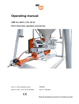
Module description
Figure 1 – Programmable microprocessor electronic
controller
A = pLAN Address selection key
B = pLAN Address display
C = Power Supply Presence LED
D = Overcharge LED
E = Fieldbus/BMS on port J26 micro switch
F = USB host (master ) port
G = USB slave (device) port
Each controller is provided with connectors for the
inputs/output and the pLAN address display, which has a
button and a LED for setting the pLAN address.
Tracer CH535 Presentation

CG-SVU007C-GB
6
4 UNT-PRC002-GB
Technical Data
FWD 08 12 20 30 45
Power supply (V/Ph/Hz) 230/1/50
Capacities
Cooling capacity on water (1) (kW) 5,2 8,3 15 18,8 30,1
Heating capacity on water (2) (kW) 6,3 11,9 18,9 20,9 38,2
Fan motor (type) 2 x direct drive centrifugal
Fan power input (3) (kW) 0,23 0,46 0,65 1,04 1,51
Current amps (3) (A) 1,1 2,2 3,1 4,7 5,5
Start-up amps (A) 3,2 5,5 9,3 14,1 16,5
Air flow
minimum (m
3
/h) 490 980 1400 1800 2700
nominal (m
3
/h) 820 1650 2300 3000 4500
maximum (m
3
/h) 980 1970 2600 3600 5400
Main coil
Water entering/leaving connections (type) ISO R7 rotating female
(Dia) 3/4" 3/4" 1 1/2" 1 1/2" 1 1/2"
Electric heater (accessory for blower only)
Electric power supply (V/Ph/Hz) 230/1/50 230/1/50 or 400/3/50 400/3/50 400/3/50 400/3/50
Heating capacity (kW) 2/4 8 10 12 12
Hot water coil (accessory for blower only)
Heating capacity (4) (kW) 6,3 12 17,4 22,4 34,5
G2 filter (filter box accessory)
Quantity 2 2 2 2 2
Dimensions ( LxWxth) (mm) 386x221x8 486x271x8 586x321x8 586*421*8 586*621*8
G4 filter (filter box accessory)
Quantity - 2 2 2 2
Dimensions ( LxWxth) (mm) - 486x264x48 586x314x48 586*414*48 586*614*48
Condensate pump (accessory) (type) Centrifugal
Water flow - lift height (l/h - mm) 24 - 500
Not available for FWD30 and FWD45
Sound level (L/M/H speed)
Sound pressure level (5) (dB(A)) 36/40/43 38/41/44 46/50/53 47/52/57 47/52/58
Sound power level (5) (dB(A)) 46/50/53 48/51/54 56/60/63 57/62/67 57/62/68
Unit dimensions
Width x Depth (mm) 890 x 600 1090 x 710 1290 x 820 1290 x 970 1290 x 1090
Height (mm) 250 300 350 450 650
Shipped unit dimensions
Width x Depth (mm) 933 x 644 1133 x 754 1333 x 864 1333 x 1008 1333*1133
Height (mm) 260 310 360 460 660
Weight (kg) 32 46 61 76 118
Colour galvanised steel
Recommended fuse size
Unit alone (aM/gI) (A) 8/16 8/16 8/16 8/25 8/25
Unit with electric heater (gI) (A) 16 (2kW),25 (4kW) 40 (230V),3*16 (400V) 3*20 3*25 3*25
(1) Conditions: Water entering/leaving temperature: 7/12 °C, Air inlet temperature 27/19°C DB/WB - Nominal air flow
(2) Conditions: Water entering/leaving temperature: 50/45 °C, Air inlet temperature 20°C DB - Nominal air flow
(3) At high speed with nominal air flow.
(4) Water entering/leaving temperature 90/70 °C, air inlet temperature 20 °C DB, Nominal air flow.
(5) A rectangular glass wool duct 1m50 long is placed on the blower.The measurement is taken in the room containing the blower unit.
Heat exchanger operating limits:
FWD:
*water temperature: max 100° C
*absolute service pressure: min 1 bar/max 11 bars
Accessories - Hot water coil:
*water temperature: min. +2° C/max. 100° C
*absolute service pressure: min 1 bar/max 11 bars
LED
Tracer CH535 provides 6 LEDs:
• 1 yellow LED indicating that the device is powered;
• 1 red LED indicating an overload on the +VDC (J2-5)
terminal;
• 4 LEDs indicating valve status:
Flashing LEDs mean the valve is moving; steadily-on
LEDs mean the valve is completely open or closed.
Table 1 – LED descriptions
LED Colour Description
A Yellow Close A (connector J27)
B Green Open A (connector J27)
C Yellow Close B (connector J28)
D Green Open B (connector J28)
Micro switches
Four micro switches are provided to configure port J26
as a Fieldbus or BMS port. They must not be modified
(Fieldbus mandatory).
USB ports
There are 2 USB ports which can be accessed after
removing the cover:
• A “host” USB port for connecting pen drives;
• A “slave” USB port for direct connection to the USB
port of a computer on which pCOManager is installed,
which can be used to upload the application program,
commissioning the system, etc.
Tracer CH535 Presentation
Serial ports
Table 2 – Serial port descriptions
Serial Type/connectors Features
Serial ZERO pLAN/J10, J11
Built into main board
• HW driver: asynchronous half duplex RS485 pLAN
• Not optically isolated
• Connectors: telephone jack + 3-pin plug-in connector
− For standard display connection
Serial ONE BMS 1 Serial Card
• Not built into main board
• HW driver: not present
• Can be used with all the BMS expansion cards of the
Tracer CH535 family
− For Modbus, BACnet, LonTalk, Web connections
Serial TWO Field Bus 1 Serial Card
• Not built into main board
• HW driver: not present
• Can be used with all Fieldbus expansion cards of the
Tracer CH535 family
− Not used
Serial THREE BMS 2 / J25
• Built into main board
• HW driver: asynchronous half duplex RS485 slave
• Optically-isolated/non-optically-isolated serial
• 3-pin plug-in connector
− For Deluxe display connection
Serial FOUR Field Bus 2 / J26
• Built into main board
• HW driver: asynchronous half duplex RS485 Master or Slave
(see par. 3.2)
• J26: optically isolated/not optically isolated
• 3-pin plug-in connector
− For Tracer CH535 ext connections

CG-SVU007C-GB
7
11UNT-PRC002-GB
Sound power levels
Discharge
Measurement conditions:
Measurements taken in a room adjacent to the room containing the FWD, at the outlet of the rectangular duct (1.5 m
long) fixed to its discharge opening.
Fan Power level in dB(A), per Hz frequency band Overall power
Unit speed 125 250 500 1000 2000 4000 8000 dB(A)
1 55 50 42 37 37 31 30 46
FWD 08 2 57 54 47 40 30 38 40 50
3 58 57 50 42 32 40 43 53
1 57 51 45 42 34 33 28 48
FWD 10 2 58 54 48 45 38 39 35 51
3 60 58 50 48 40 42 39 54
1 57 51 45 42 34 33 28 48
FWD 12 2 58 54 48 45 38 39 35 51
3 60 58 50 48 40 42 39 54
1 56 62 50 48 39 38 36 56
FWD 14 2 61 66 55 53 47 46 45 60
3 63 69 58 56 50 50 49 63
1 57 63 51 49 40 39 37 57
FWD 20 2 61 66 55 53 47 46 45 60
3 63 69 58 56 50 50 49 63
Intake
Measurement conditions:
Measurements taken at the horizontal air intake.
Fan Power level in dB(A), per Hz frequency band Overall power
Unit speed 125 250 500 1000 2000 4000 8000 dB(A)
1 56 55 55 53 46 45 42 57
FWD 08 2 63 62 60 60 53 53 53 64
3 66 65 63 62 56 55 57 67
1 62 58 55 58 51 48 44 61
FWD 10 2 66 63 60 62 56 55 52 66
3 70 67 63 65 59 59 57 69
1 62 58 55 58 51 48 44 61
FWD 12 2 66 63 60 62 56 55 52 66
3 70 67 63 65 59 59 57 69
1 66 65 65 65 57 50 46 68
FWD 14 2 73 72 69 71 64 59 57 74
3 78 76 73 75 69 64 63 78
1 68 72 64 64 56 52 50 69
FWD 20 2 76 76 68 71 65 61 61 75
3 78 79 71 74 69 66 66 78
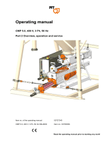
Tracer CH535 Hardware
Built-In driver module connections terminals
Figure 2 – Built-in driver terminal locations
C1
NO1
NO2
NO3
A
B
C D
C1
C4
NO4
NO5
NO6
C4
C7
NO7
C7
NO8
C8
NC8
NO12
C12
NC12
NO13
C13
NC13
C9
NO9
NO10
NO11
C9
G
G0
U1
U2
U3
GND
+VDC
+Vterm
GND
+5 V
REF
U4
GND
U5
GND
VG
VG0
Y1
Y2
Y3
Y4
ID1
ID2
ID3
ID4
ID5
ID6
ID7
ID8
IDC1
U6
U7
U8
GND
ID9
ID10
ID11
ID12
IDC9
ID13H
ID13
IDC13
ID14
ID14H
J1
J24 J2 J3
J4
J5
J7
J8
J14
J10
J13
J12
J16
J17
J18
J15
J6
drac SMBdrac suBdleiF
J11 pLAN
J25
BMS2
J26
FBus2
4 3 2 1
4
5
1
6
2 3 3 3 8
9
7 8
10
11
22 24
12
15
18
16 17
20
21
13 14
J27
1
3
2
4
J28
1
3
2
4
driver
VBAT
G0
G
J30
23
GND
VREF
S1
S2
S3
S4
DI1
DI2
J29
1 = Power Supply connection (G (+) , GO (-) )
2 = +Vterm: additional terminal power supply
-VREF power supply for rasiometric probes
3 = Universal Input / Outputs
4 = +VDC: power supply for active probes
5 = pLAN address setup key, secondary display LED
6 = VG: power supply voltage A for options
VG0: power supply for optically isolated analog output at 0 Vac/Vdc
7 = Analog ouputs
8 = ID: digital inputs at low voltage
9 = ID..: digital inputs at low voltage
IDH..: digital inputs at high voltage
10 = pLAN telephone connector for terminal/download application programme
11 = pLAN removable connector
12 = Reserved
13 = Reserved
14 = Reserved
15 = Relay digital outputs

CG-SVU007C-GB
8
4 UNT-PRC002-GB
Technical Data
FWD 08 12 20 30 45
Power supply (V/Ph/Hz) 230/1/50
Capacities
Cooling capacity on water (1) (kW) 5,2 8,3 15 18,8 30,1
Heating capacity on water (2) (kW) 6,3 11,9 18,9 20,9 38,2
Fan motor (type) 2 x direct drive centrifugal
Fan power input (3) (kW) 0,23 0,46 0,65 1,04 1,51
Current amps (3) (A) 1,1 2,2 3,1 4,7 5,5
Start-up amps (A) 3,2 5,5 9,3 14,1 16,5
Air flow
minimum (m
3
/h) 490 980 1400 1800 2700
nominal (m
3
/h) 820 1650 2300 3000 4500
maximum (m
3
/h) 980 1970 2600 3600 5400
Main coil
Water entering/leaving connections (type) ISO R7 rotating female
(Dia) 3/4" 3/4" 1 1/2" 1 1/2" 1 1/2"
Electric heater (accessory for blower only)
Electric power supply (V/Ph/Hz) 230/1/50 230/1/50 or 400/3/50 400/3/50 400/3/50 400/3/50
Heating capacity (kW) 2/4 8 10 12 12
Hot water coil (accessory for blower only)
Heating capacity (4) (kW) 6,3 12 17,4 22,4 34,5
G2 filter (filter box accessory)
Quantity 2 2 2 2 2
Dimensions ( LxWxth) (mm) 386x221x8 486x271x8 586x321x8 586*421*8 586*621*8
G4 filter (filter box accessory)
Quantity - 2 2 2 2
Dimensions ( LxWxth) (mm) - 486x264x48 586x314x48 586*414*48 586*614*48
Condensate pump (accessory) (type) Centrifugal
Water flow - lift height (l/h - mm) 24 - 500
Not available for FWD30 and FWD45
Sound level (L/M/H speed)
Sound pressure level (5) (dB(A)) 36/40/43 38/41/44 46/50/53 47/52/57 47/52/58
Sound power level (5) (dB(A)) 46/50/53 48/51/54 56/60/63 57/62/67 57/62/68
Unit dimensions
Width x Depth (mm) 890 x 600 1090 x 710 1290 x 820 1290 x 970 1290 x 1090
Height (mm) 250 300 350 450 650
Shipped unit dimensions
Width x Depth (mm) 933 x 644 1133 x 754 1333 x 864 1333 x 1008 1333*1133
Height (mm) 260 310 360 460 660
Weight (kg) 32 46 61 76 118
Colour galvanised steel
Recommended fuse size
Unit alone (aM/gI) (A) 8/16 8/16 8/16 8/25 8/25
Unit with electric heater (gI) (A) 16 (2kW),25 (4kW) 40 (230V),3*16 (400V) 3*20 3*25 3*25
(1) Conditions: Water entering/leaving temperature: 7/12 °C, Air inlet temperature 27/19°C DB/WB - Nominal air flow
(2) Conditions: Water entering/leaving temperature: 50/45 °C, Air inlet temperature 20°C DB - Nominal air flow
(3) At high speed with nominal air flow.
(4) Water entering/leaving temperature 90/70 °C, air inlet temperature 20 °C DB, Nominal air flow.
(5) A rectangular glass wool duct 1m50 long is placed on the blower.The measurement is taken in the room containing the blower unit.
Heat exchanger operating limits:
FWD:
*water temperature: max 100° C
*absolute service pressure: min 1 bar/max 11 bars
Accessories - Hot water coil:
*water temperature: min. +2° C/max. 100° C
*absolute service pressure: min 1 bar/max 11 bars
Tracer CH535 Extention Hardware
Figure 3 – CH535 extention terminal locations
G
ID1
ID2
ID4
ID3
IDC1
G0
VG
GND
T+
T-
VG0
Y1
B1
B3
B4
GND
NO1
C1
NC1
NO2
C2
NC2
NO3
C3
NC3
NO4
C4
NC4
+Vdc
B2
GND
+5VRef
+5VRef
+Vdc
8
7
4
1
2
5
3
6
1 = Power Supply connection (G (+), G0 (-))
2 = Optically-isolated analog output, 0 to 10 V
3 = RS485 network connector (GND, T+, T-)
4 = Optically-isolated digital inputs, at 24 Vac/Vdc
5 = Yellow power LED and 3 indicator LEDs
6 = Serial address
7 = Analog inputs and power to probes
8 = Relay digital outputs

CG-SVU007C-GB
9
11UNT-PRC002-GB
Sound power levels
Discharge
Measurement conditions:
Measurements taken in a room adjacent to the room containing the FWD, at the outlet of the rectangular duct (1.5 m
long) fixed to its discharge opening.
Fan Power level in dB(A), per Hz frequency band Overall power
Unit speed 125 250 500 1000 2000 4000 8000 dB(A)
1 55 50 42 37 37 31 30 46
FWD 08 2 57 54 47 40 30 38 40 50
3 58 57 50 42 32 40 43 53
1 57 51 45 42 34 33 28 48
FWD 10 2 58 54 48 45 38 39 35 51
3 60 58 50 48 40 42 39 54
1 57 51 45 42 34 33 28 48
FWD 12 2 58 54 48 45 38 39 35 51
3 60 58 50 48 40 42 39 54
1 56 62 50 48 39 38 36 56
FWD 14 2 61 66 55 53 47 46 45 60
3 63 69 58 56 50 50 49 63
1 57 63 51 49 40 39 37 57
FWD 20 2 61 66 55 53 47 46 45 60
3 63 69 58 56 50 50 49 63
Intake
Measurement conditions:
Measurements taken at the horizontal air intake.
Fan Power level in dB(A), per Hz frequency band Overall power
Unit speed 125 250 500 1000 2000 4000 8000 dB(A)
1 56 55 55 53 46 45 42 57
FWD 08 2 63 62 60 60 53 53 53 64
3 66 65 63 62 56 55 57 67
1 62 58 55 58 51 48 44 61
FWD 10 2 66 63 60 62 56 55 52 66
3 70 67 63 65 59 59 57 69
1 62 58 55 58 51 48 44 61
FWD 12 2 66 63 60 62 56 55 52 66
3 70 67 63 65 59 59 57 69
1 66 65 65 65 57 50 46 68
FWD 14 2 73 72 69 71 64 59 57 74
3 78 76 73 75 69 64 63 78
1 68 72 64 64 56 52 50 69
FWD 20 2 76 76 68 71 65 61 61 75
3 78 79 71 74 69 66 66 78
TRACER CH535 offers customer the possibility to use
inputs or outputs in order to:
• use an external water setpoint reset using an analog
input (option),
• use an auxiliary setpoint (option),
• connect a remote on/off of the circuit/unit (standard),
• connect a remote Cooling/Heating switch (standard),
• return a circuit fault (option),
• receive unit capacity percent (option).
Note: External water setpoint based on an external
signal input (0-20mA or 4-20mA), it will be possible to
offset the active setpoint from 0°C to 20°C. This function
can be used in conjunction with the automatic setpoint
reset function.
5
1
4
2 3
1 = Leaving water temperature setpoint
2 = Minimum value
3 = Maximum value
4 = Reset = 20°C
5 = Active setpoint
Note: External demand limit setpoint based on an
external signal input (0-20mA or 4-20mA), it will define
the number of compressors allowed to start.
Table 3 – External demand limit setpoint allowances
Nb of CMP allowed
Percent
Current
0-20mA
Simplex
Duo
Simplex
Trio
Duplex
0.0% 0 1 1 1
25.0% 5 1 1 2
33.3% 6.66 1 2 2
50.0% 10 2 2 3
66.7% 13.34 2 3 3
75.0% 15 2 3 4
100.0% 20 2 3 4
Nb of CMP allowed
Percent
Current
4-20mA
Simplex
Duo
Simplex
Trio
Duplex
20.0% 4 1 1 1
40.0% 8 1 1 2
46.7% 9.33 1 2 2
60.0% 12 2 2 3
73.4% 14.67 2 3 3
80.0% 16 2 3 4
100.0% 20 2 3 4
Tracer CH535 module connections Terminals
Water setpoint
Ambient
temperature

CG-SVU007C-GB
10
4 UNT-PRC002-GB
Technical Data
FWD 08 12 20 30 45
Power supply (V/Ph/Hz) 230/1/50
Capacities
Cooling capacity on water (1) (kW) 5,2 8,3 15 18,8 30,1
Heating capacity on water (2) (kW) 6,3 11,9 18,9 20,9 38,2
Fan motor (type) 2 x direct drive centrifugal
Fan power input (3) (kW) 0,23 0,46 0,65 1,04 1,51
Current amps (3) (A) 1,1 2,2 3,1 4,7 5,5
Start-up amps (A) 3,2 5,5 9,3 14,1 16,5
Air flow
minimum (m
3
/h) 490 980 1400 1800 2700
nominal (m
3
/h) 820 1650 2300 3000 4500
maximum (m
3
/h) 980 1970 2600 3600 5400
Main coil
Water entering/leaving connections (type) ISO R7 rotating female
(Dia) 3/4" 3/4" 1 1/2" 1 1/2" 1 1/2"
Electric heater (accessory for blower only)
Electric power supply (V/Ph/Hz) 230/1/50 230/1/50 or 400/3/50 400/3/50 400/3/50 400/3/50
Heating capacity (kW) 2/4 8 10 12 12
Hot water coil (accessory for blower only)
Heating capacity (4) (kW) 6,3 12 17,4 22,4 34,5
G2 filter (filter box accessory)
Quantity 2 2 2 2 2
Dimensions ( LxWxth) (mm) 386x221x8 486x271x8 586x321x8 586*421*8 586*621*8
G4 filter (filter box accessory)
Quantity - 2 2 2 2
Dimensions ( LxWxth) (mm) - 486x264x48 586x314x48 586*414*48 586*614*48
Condensate pump (accessory) (type) Centrifugal
Water flow - lift height (l/h - mm) 24 - 500
Not available for FWD30 and FWD45
Sound level (L/M/H speed)
Sound pressure level (5) (dB(A)) 36/40/43 38/41/44 46/50/53 47/52/57 47/52/58
Sound power level (5) (dB(A)) 46/50/53 48/51/54 56/60/63 57/62/67 57/62/68
Unit dimensions
Width x Depth (mm) 890 x 600 1090 x 710 1290 x 820 1290 x 970 1290 x 1090
Height (mm) 250 300 350 450 650
Shipped unit dimensions
Width x Depth (mm) 933 x 644 1133 x 754 1333 x 864 1333 x 1008 1333*1133
Height (mm) 260 310 360 460 660
Weight (kg) 32 46 61 76 118
Colour galvanised steel
Recommended fuse size
Unit alone (aM/gI) (A) 8/16 8/16 8/16 8/25 8/25
Unit with electric heater (gI) (A) 16 (2kW),25 (4kW) 40 (230V),3*16 (400V) 3*20 3*25 3*25
(1) Conditions: Water entering/leaving temperature: 7/12 °C, Air inlet temperature 27/19°C DB/WB - Nominal air flow
(2) Conditions: Water entering/leaving temperature: 50/45 °C, Air inlet temperature 20°C DB - Nominal air flow
(3) At high speed with nominal air flow.
(4) Water entering/leaving temperature 90/70 °C, air inlet temperature 20 °C DB, Nominal air flow.
(5) A rectangular glass wool duct 1m50 long is placed on the blower.The measurement is taken in the room containing the blower unit.
Heat exchanger operating limits:
FWD:
*water temperature: max 100° C
*absolute service pressure: min 1 bar/max 11 bars
Accessories - Hot water coil:
*water temperature: min. +2° C/max. 100° C
*absolute service pressure: min 1 bar/max 11 bars
Alarms display and resetting
A fault on a unit will be shown through the user interface
or through 2 digital outputs, one for each refrigerant
circuit. The alarms are divided into 3 categories:
Warning: Shows that something is wrong on the unit but
unit can be kept in operation. A message is displayed
on the user interface screen. These messages are not
recorded in the history list.
Fault with automatic reset: when the cause of the fault
disappears, the fault is cancelled and unit operation
will return to normal. The messages displayed on the
user interface screen disappear but are recorded in the
history list of faults. The fault is relayed through the
digital output if I/O parameter is set to show a circuit
fault.
Fault with manual reset: when the cause of the fault
disappears, a manual reset is required to restart the unit.
The messages displayed on the user interface screen
disappear and are recorded in the history list of faults.
The fault is relayed through the digital output if I/O
parameter is set to show a circuit fault.
Should an alarm occur,
will be lit in red.
Pressing
once will display the alarm message (refer
to Table 6 for possible messages)
When alarm message is displayed press
to reset
the default if necessary.
Alarms

CG-SVU007C-GB
11
11UNT-PRC002-GB
Sound power levels
Discharge
Measurement conditions:
Measurements taken in a room adjacent to the room containing the FWD, at the outlet of the rectangular duct (1.5 m
long) fixed to its discharge opening.
Fan Power level in dB(A), per Hz frequency band Overall power
Unit speed 125 250 500 1000 2000 4000 8000 dB(A)
1 55 50 42 37 37 31 30 46
FWD 08 2 57 54 47 40 30 38 40 50
3 58 57 50 42 32 40 43 53
1 57 51 45 42 34 33 28 48
FWD 10 2 58 54 48 45 38 39 35 51
3 60 58 50 48 40 42 39 54
1 57 51 45 42 34 33 28 48
FWD 12 2 58 54 48 45 38 39 35 51
3 60 58 50 48 40 42 39 54
1 56 62 50 48 39 38 36 56
FWD 14 2 61 66 55 53 47 46 45 60
3 63 69 58 56 50 50 49 63
1 57 63 51 49 40 39 37 57
FWD 20 2 61 66 55 53 47 46 45 60
3 63 69 58 56 50 50 49 63
Intake
Measurement conditions:
Measurements taken at the horizontal air intake.
Fan Power level in dB(A), per Hz frequency band Overall power
Unit speed 125 250 500 1000 2000 4000 8000 dB(A)
1 56 55 55 53 46 45 42 57
FWD 08 2 63 62 60 60 53 53 53 64
3 66 65 63 62 56 55 57 67
1 62 58 55 58 51 48 44 61
FWD 10 2 66 63 60 62 56 55 52 66
3 70 67 63 65 59 59 57 69
1 62 58 55 58 51 48 44 61
FWD 12 2 66 63 60 62 56 55 52 66
3 70 67 63 65 59 59 57 69
1 66 65 65 65 57 50 46 68
FWD 14 2 73 72 69 71 64 59 57 74
3 78 76 73 75 69 64 63 78
1 68 72 64 64 56 52 50 69
FWD 20 2 76 76 68 71 65 61 61 75
3 78 79 71 74 69 66 66 78
Alarms
Table 4 - Status, Warning and Alarm messages
N° Message
Reset
Type
Unit Status Description
1 No Alarm - Unit On See unit status on Main display
2 Alarm Water Pump1 Manual Unit On Defective water pump 1
3 Alarm Water Pump2 Manual Unit On Defective water pump 2
4 User Ckt1 Stop - Circuit 1 Off Circuit 1 Disable by Settings (via keyboard)
5 User Ckt2 Stop - Circuit 2 Off Circuit 2 Disable by Settings (via keyboard)
6 Ext. Ckt1 Stop - Circuit 1 Off Circuit 1 Off by Digital Input (Duplex units)
7 Ext. Ckt2 Stop - Circuit 2 Off Circuit 2 Off by Digital Input (Duplex units)
8 Rem. Ckt1 Stop - Circuit 1 Off Circuit 1 Disable by Supervision
9 Rem. Ckt2 Stop - Circuit 2 Off Circuit 2 Disable by Supervision
10 Clock Unit Stop - Unit Off Unit Off by Program (Hourly, Weekly)
11 Operator Stop - Unit Off Unit Off by Operator (via keyboard)
12 Phase Fault Auto Unit Off Phase Loss or Phase Reversal
13 Warning Ckt1 LP Limit Auto Circuit 1 Limit
Suction pressure on circuit 1 is below the setpoint
(1.5barG).
14 Warning Ckt2 LP Limit Auto Circuit 2 Limit
Suction pressure on circuit 2 is below the setpoint
(1.5barG).
15 Warning Ckt1 HW Limit Auto Circuit 1 Limit
Leaving water temperature is above the setpoint
(Default value: 25°C).
16 Warning Ckt2 HW Limit Auto Circuit 2 Limit
Leaving water temperature is above the setpoint
(Default value: 25°C).
17 Warning Ckt1 HP Limit Auto Circuit 1 Limit
Discharge pressure on circuit 1 is above the
setpoint (Default value: 43.1barG).
18 Warning Ckt2 HP Limit Auto Circuit 2 Limit
Discharge pressure on circuit 2 is above the
setpoint (Default value: 43.1barG).
19 Warning Ckt1 HT Limit Auto Circuit 1 Limit
Discharge temperature on circuit 1 is above the
setpoint (Default value: 128°C).
20 Warning Ckt2 HT Limit Auto Circuit 2 Limit
Discharge temperature on circuit 2 is above the
setpoint (Default value: 128°C).
21 Warning Ckt1 CIPD Limit Auto Circuit 1 Limit
Compressor Involute Pressure Differential on
circuit 1 is above 22.2barG or above 18.6barG
during 25min.
22 Warning Ckt2 CIPD Limit Auto Circuit 2 Limit
Compressor Involute Pressure Differential on
circuit 2 is above 22.2barG or above 18.6barG
during 25min.
23
Warning Low SuperHeat
ckt1
Auto Circuit 1 Off Super Heat on circuit 1 is below low limit (2°C)
24
Warning Low SuperHeat
ckt2
Auto Circuit 2 Off Super Heat on circuit 2 is below low limit (2°C)
25
Alarm Outside Air Temp
Auto Unit Off
Ambient temperature is out of range for unit
operation:
Cooling: Too Low Cooling mode: below -10°C (default value)
Heating: Out of Range
Heating mode: below -15°C (default value) or
above 29°C.
26 Ckt1 Defrost - Unit On Defrost on Circuit 1

CG-SVU007C-GB
12
4 UNT-PRC002-GB
Technical Data
FWD 08 12 20 30 45
Power supply (V/Ph/Hz) 230/1/50
Capacities
Cooling capacity on water (1) (kW) 5,2 8,3 15 18,8 30,1
Heating capacity on water (2) (kW) 6,3 11,9 18,9 20,9 38,2
Fan motor (type) 2 x direct drive centrifugal
Fan power input (3) (kW) 0,23 0,46 0,65 1,04 1,51
Current amps (3) (A) 1,1 2,2 3,1 4,7 5,5
Start-up amps (A) 3,2 5,5 9,3 14,1 16,5
Air flow
minimum (m
3
/h) 490 980 1400 1800 2700
nominal (m
3
/h) 820 1650 2300 3000 4500
maximum (m
3
/h) 980 1970 2600 3600 5400
Main coil
Water entering/leaving connections (type) ISO R7 rotating female
(Dia) 3/4" 3/4" 1 1/2" 1 1/2" 1 1/2"
Electric heater (accessory for blower only)
Electric power supply (V/Ph/Hz) 230/1/50 230/1/50 or 400/3/50 400/3/50 400/3/50 400/3/50
Heating capacity (kW) 2/4 8 10 12 12
Hot water coil (accessory for blower only)
Heating capacity (4) (kW) 6,3 12 17,4 22,4 34,5
G2 filter (filter box accessory)
Quantity 2 2 2 2 2
Dimensions ( LxWxth) (mm) 386x221x8 486x271x8 586x321x8 586*421*8 586*621*8
G4 filter (filter box accessory)
Quantity - 2 2 2 2
Dimensions ( LxWxth) (mm) - 486x264x48 586x314x48 586*414*48 586*614*48
Condensate pump (accessory) (type) Centrifugal
Water flow - lift height (l/h - mm) 24 - 500
Not available for FWD30 and FWD45
Sound level (L/M/H speed)
Sound pressure level (5) (dB(A)) 36/40/43 38/41/44 46/50/53 47/52/57 47/52/58
Sound power level (5) (dB(A)) 46/50/53 48/51/54 56/60/63 57/62/67 57/62/68
Unit dimensions
Width x Depth (mm) 890 x 600 1090 x 710 1290 x 820 1290 x 970 1290 x 1090
Height (mm) 250 300 350 450 650
Shipped unit dimensions
Width x Depth (mm) 933 x 644 1133 x 754 1333 x 864 1333 x 1008 1333*1133
Height (mm) 260 310 360 460 660
Weight (kg) 32 46 61 76 118
Colour galvanised steel
Recommended fuse size
Unit alone (aM/gI) (A) 8/16 8/16 8/16 8/25 8/25
Unit with electric heater (gI) (A) 16 (2kW),25 (4kW) 40 (230V),3*16 (400V) 3*20 3*25 3*25
(1) Conditions: Water entering/leaving temperature: 7/12 °C, Air inlet temperature 27/19°C DB/WB - Nominal air flow
(2) Conditions: Water entering/leaving temperature: 50/45 °C, Air inlet temperature 20°C DB - Nominal air flow
(3) At high speed with nominal air flow.
(4) Water entering/leaving temperature 90/70 °C, air inlet temperature 20 °C DB, Nominal air flow.
(5) A rectangular glass wool duct 1m50 long is placed on the blower.The measurement is taken in the room containing the blower unit.
Heat exchanger operating limits:
FWD:
*water temperature: max 100° C
*absolute service pressure: min 1 bar/max 11 bars
Accessories - Hot water coil:
*water temperature: min. +2° C/max. 100° C
*absolute service pressure: min 1 bar/max 11 bars
Alarms
N° Message
Reset
Type
Unit Status Description
27 Ckt2 Defrost - Unit On Defrost on Circuit 2
28 Alarm Loss of Water Flow Auto Unit Off
Lossofwaterowformorethan1sec.Pump
restarts by a manual unit mode changeover
29 Alarm Air Sensor Auto Unit Off
Faulty sensor, out of range -30..+80°C
(short circuit or open circuit)
30 Alarm Water In Sensor Auto Unit Off
Faulty sensor, out of range -30..+80°C
(short circuit or open circuit)
31 Alarm Water Out Sensor Auto Unit Off
Faulty sensor, out of range -30..+80°C
(short circuit or open circuit) (short circuit or open
circuit)
32 Alarm HT Sensor Ckt1 Auto Circuit 1 Off
Faulty sensor, out of range -30..+150°C
(short circuit or open circuit)
33 Alarm HP Sensor Ckt1 Auto Circuit 1 Off
Faulty sensor, out of range 1..46Bar
(short circuit or open circuit)
34 Alarm HT Sensor Ckt2 Auto Circuit 2 Off
Faulty sensor, out of range -30..+150°C
(short circuit or open circuit)
35 Alarm HP Sensor Ckt2 Auto Circuit 2 Off
Faulty sensor, out of range 1..46Bar
(short circuit or open circuit)
36 Alarm PHR LWT Sensor Auto Unit On
Faulty sensor, out of range -30..+80°C
(short circuit or open circuit)
37 Alarm PHR EWT Sensor Auto Unit On
Faulty sensor, out of range -30..+80°C
(short circuit or open circuit)
38
Alarm Ext. Water SP
Signal
Auto Unit On
Faulty signal, out of range 0..20mA or 4..20mA
followingconguration
39
Alarm Ext. Demand Limit
SP Signal
Auto Unit On
Faulty signal, out of range 0..20mA or 4..20mA
followingconguration
40 Alarm Fan1 fault Ckt1
Auto /
Manual
Circuit 1 On
(Off if only one
fan)
The 1st fan on the circuit 1 is faulty
41 Alarm Fan1 fault Ckt2
Auto /
Manual
Circuit 2 On
(Off if only one
fan)
The 1st fan on the circuit 2 is faulty
42 Alarm LP Ckt1 Fault
Auto /
Manual
Circuit 1 Off
Suction pressure on circuit 1 is below the setpoint.
Manual reset after 3 faults within 1 hour
43 Alarm LP Ckt2 Fault
Auto /
Manual
Circuit 2 Off
Suction pressure on circuit 2 is below the setpoint.
Manual reset after 3 faults within 1 hour
44 Alarm Comp. 1A Fault Manual CMP 1A Off CMP 1A is faulty
45 Alarm Comp. 1B Fault Manual CMP 1B Off CMP 1B is faulty
46 Alarm Comp. 1C Fault Manual CMP 1C Off CMP 1C is faulty
47 Alarm Comp. 2A Fault Manual CMP 2A Off CMP 2A is faulty
48 Alarm Comp. 2B Fault Manual CMP 2B Off CMP 2B is faulty

CG-SVU007C-GB
13
11UNT-PRC002-GB
Sound power levels
Discharge
Measurement conditions:
Measurements taken in a room adjacent to the room containing the FWD, at the outlet of the rectangular duct (1.5 m
long) fixed to its discharge opening.
Fan Power level in dB(A), per Hz frequency band Overall power
Unit speed 125 250 500 1000 2000 4000 8000 dB(A)
1 55 50 42 37 37 31 30 46
FWD 08 2 57 54 47 40 30 38 40 50
3 58 57 50 42 32 40 43 53
1 57 51 45 42 34 33 28 48
FWD 10 2 58 54 48 45 38 39 35 51
3 60 58 50 48 40 42 39 54
1 57 51 45 42 34 33 28 48
FWD 12 2 58 54 48 45 38 39 35 51
3 60 58 50 48 40 42 39 54
1 56 62 50 48 39 38 36 56
FWD 14 2 61 66 55 53 47 46 45 60
3 63 69 58 56 50 50 49 63
1 57 63 51 49 40 39 37 57
FWD 20 2 61 66 55 53 47 46 45 60
3 63 69 58 56 50 50 49 63
Intake
Measurement conditions:
Measurements taken at the horizontal air intake.
Fan Power level in dB(A), per Hz frequency band Overall power
Unit speed 125 250 500 1000 2000 4000 8000 dB(A)
1 56 55 55 53 46 45 42 57
FWD 08 2 63 62 60 60 53 53 53 64
3 66 65 63 62 56 55 57 67
1 62 58 55 58 51 48 44 61
FWD 10 2 66 63 60 62 56 55 52 66
3 70 67 63 65 59 59 57 69
1 62 58 55 58 51 48 44 61
FWD 12 2 66 63 60 62 56 55 52 66
3 70 67 63 65 59 59 57 69
1 66 65 65 65 57 50 46 68
FWD 14 2 73 72 69 71 64 59 57 74
3 78 76 73 75 69 64 63 78
1 68 72 64 64 56 52 50 69
FWD 20 2 76 76 68 71 65 61 61 75
3 78 79 71 74 69 66 66 78
Alarms
N° Message
Reset
Type
Unit Status Description
49
Warning Comp.1A
Maintenance
Manual Unit On
Compressor running hours above the threshold
denedinunitconguration.Eachcompressor
start is equal to 3 running hours.
50
Warning Comp.1B
Maintenance
Manual Unit On
51
Warning Comp.1C
Maintenance
Manual Unit On
52
Warning Comp.2A
Maintenance
Manual Unit On
53
Warning Comp.2B
Maintenance
Manual Unit On
54 Alarm HT Ckt 1 Fault Manual Circuit 1 Off High Discharge Temperature Fault on Ckt1
55 Alarm HT Ckt 2 Fault Manual Circuit 2 Off High Discharge Temperature Fault on Ckt2
56
Alarm CMP Involute Press
Diff Ckt 1
Manual Circuit 1 Off
High CMP Involute Pressure Differential Fault on
Ckt1
57
Alarm CMP Involute Press
Diff Ckt 2
Manual Circuit 2 Off
High CMP Involute Pressure Differential Fault on
Ckt2
58
Alarm Low Sat Suction
Temp Ckt 1
Manual Circuit 1 Off Low Suction Saturated Temperature Fault on Ckt1
59
Alarm Low Sat Suction
Temp Ckt 2
Manual Circuit 2 Off Low Suction Saturated Temperature Fault on Ckt2
60
Alarm Low SuperHeat
Ckt1
Manual Circuit 1 Off
Low Super Heat warning on circuit 1 occurred
three times in one hour
61
Alarm Low SuperHeat
Ckt2
Manual Circuit 2 Off
Low Super Heat warning on circuit 2 occurred
three times in one hour
62
Alarm Low water
temperature
Manual Unit Off
LWT < antifreeze or INT (antifreeze-
EWT)<=10°Cxsecond
63 Alarm HP Ckt1 Fault Manual Circuit 1 Off High Pressure Cut-Out circuit 1
64 Alarm HP Ckt2 Fault Manual Circuit 2 Off High Pressure Cut-Out circuit 2
65
Alarm Ckt 1 Fault (1st
fan or all CMP)
Manual Circuit 1 Off
Simultaneous faults on compressors 1A and 1B
(1A, 1B and 1C for units #36, #39 and #45) or
Fan 1 Fault Ckt1 for units #7 to #20, #35 and
#40.
66
Alarm Ckt 2 Fault (1st
fan or all CMP)
Manual Circuit 2 Off
Simultaneous faults on compressors 2A and 2B
or Fan 1 Fault Ckt2 for units #7 to #20, #35 and
#40.
67 Alarm Unit Fault Manual Unit Off
Simultaneous faults on Ckt1 and Ckt2 on duplex
units
68 AlarmspCOe5ofine Auto Unit On pCOextension5isofine
69
Alarms pCOe 5 Analog
input 1
Auto Unit On pCOextension5 is in default on Analog input #1
70
Alarms pCOe 5 Analog
input 2
Auto Unit On pCOextension5 is in default on Analog input #2
71
Alarms pCOe 5 Analog
input 3
Auto Unit On pCOextension5 is in default on Analog input #3
72
Alarms pCOe 5 Analog
input 4
Auto Unit On pCOextension5 is in default on Analog input #4

CG-SVU007C-GB
14
4 UNT-PRC002-GB
Technical Data
FWD 08 12 20 30 45
Power supply (V/Ph/Hz) 230/1/50
Capacities
Cooling capacity on water (1) (kW) 5,2 8,3 15 18,8 30,1
Heating capacity on water (2) (kW) 6,3 11,9 18,9 20,9 38,2
Fan motor (type) 2 x direct drive centrifugal
Fan power input (3) (kW) 0,23 0,46 0,65 1,04 1,51
Current amps (3) (A) 1,1 2,2 3,1 4,7 5,5
Start-up amps (A) 3,2 5,5 9,3 14,1 16,5
Air flow
minimum (m
3
/h) 490 980 1400 1800 2700
nominal (m
3
/h) 820 1650 2300 3000 4500
maximum (m
3
/h) 980 1970 2600 3600 5400
Main coil
Water entering/leaving connections (type) ISO R7 rotating female
(Dia) 3/4" 3/4" 1 1/2" 1 1/2" 1 1/2"
Electric heater (accessory for blower only)
Electric power supply (V/Ph/Hz) 230/1/50 230/1/50 or 400/3/50 400/3/50 400/3/50 400/3/50
Heating capacity (kW) 2/4 8 10 12 12
Hot water coil (accessory for blower only)
Heating capacity (4) (kW) 6,3 12 17,4 22,4 34,5
G2 filter (filter box accessory)
Quantity 2 2 2 2 2
Dimensions ( LxWxth) (mm) 386x221x8 486x271x8 586x321x8 586*421*8 586*621*8
G4 filter (filter box accessory)
Quantity - 2 2 2 2
Dimensions ( LxWxth) (mm) - 486x264x48 586x314x48 586*414*48 586*614*48
Condensate pump (accessory) (type) Centrifugal
Water flow - lift height (l/h - mm) 24 - 500
Not available for FWD30 and FWD45
Sound level (L/M/H speed)
Sound pressure level (5) (dB(A)) 36/40/43 38/41/44 46/50/53 47/52/57 47/52/58
Sound power level (5) (dB(A)) 46/50/53 48/51/54 56/60/63 57/62/67 57/62/68
Unit dimensions
Width x Depth (mm) 890 x 600 1090 x 710 1290 x 820 1290 x 970 1290 x 1090
Height (mm) 250 300 350 450 650
Shipped unit dimensions
Width x Depth (mm) 933 x 644 1133 x 754 1333 x 864 1333 x 1008 1333*1133
Height (mm) 260 310 360 460 660
Weight (kg) 32 46 61 76 118
Colour galvanised steel
Recommended fuse size
Unit alone (aM/gI) (A) 8/16 8/16 8/16 8/25 8/25
Unit with electric heater (gI) (A) 16 (2kW),25 (4kW) 40 (230V),3*16 (400V) 3*20 3*25 3*25
(1) Conditions: Water entering/leaving temperature: 7/12 °C, Air inlet temperature 27/19°C DB/WB - Nominal air flow
(2) Conditions: Water entering/leaving temperature: 50/45 °C, Air inlet temperature 20°C DB - Nominal air flow
(3) At high speed with nominal air flow.
(4) Water entering/leaving temperature 90/70 °C, air inlet temperature 20 °C DB, Nominal air flow.
(5) A rectangular glass wool duct 1m50 long is placed on the blower.The measurement is taken in the room containing the blower unit.
Heat exchanger operating limits:
FWD:
*water temperature: max 100° C
*absolute service pressure: min 1 bar/max 11 bars
Accessories - Hot water coil:
*water temperature: min. +2° C/max. 100° C
*absolute service pressure: min 1 bar/max 11 bars
Alarms
N° Message
Reset
Type
Unit Status Description
73
Alarms pCOe 5 IO
mismatch
Auto Unit On pCOextension5 is in default on Analog input #4
74 Alarm Drive Fault Manual Unit Off Variable Primary Flow Drive fault
75
Alarm Low Differential
Pressure ckt1
Auto Circuit 1 Off
Low Differential Pressure on circuit 1 (High
Pressure - Low Pressure)
76
Alarm Low Differential
Pressure ckt2
Auto Circuit 2 Off
Low Differential Pressure on circuit 2 (High
Pressure - Low Pressure)
77
Warning Cutout Supp
Heating
Auto Unit On
Information that Supplemental Heating is in cut
out
78 Warning LRTC limit ckt1 Auto Circuit 1 Limit Low Refrigerant Temperature cut-out on circuit 1
79 Warning LRTC limit ckt2 Auto Circuit 2 Limit Low Refrigerant Temperature cut-out on circuit 2
80
EVD EVO EXV synchro
Please wait
Auto Unit Off Expansion Valve is currently initiating

CG-SVU007C-GB
15
11UNT-PRC002-GB
Sound power levels
Discharge
Measurement conditions:
Measurements taken in a room adjacent to the room containing the FWD, at the outlet of the rectangular duct (1.5 m
long) fixed to its discharge opening.
Fan Power level in dB(A), per Hz frequency band Overall power
Unit speed 125 250 500 1000 2000 4000 8000 dB(A)
1 55 50 42 37 37 31 30 46
FWD 08 2 57 54 47 40 30 38 40 50
3 58 57 50 42 32 40 43 53
1 57 51 45 42 34 33 28 48
FWD 10 2 58 54 48 45 38 39 35 51
3 60 58 50 48 40 42 39 54
1 57 51 45 42 34 33 28 48
FWD 12 2 58 54 48 45 38 39 35 51
3 60 58 50 48 40 42 39 54
1 56 62 50 48 39 38 36 56
FWD 14 2 61 66 55 53 47 46 45 60
3 63 69 58 56 50 50 49 63
1 57 63 51 49 40 39 37 57
FWD 20 2 61 66 55 53 47 46 45 60
3 63 69 58 56 50 50 49 63
Intake
Measurement conditions:
Measurements taken at the horizontal air intake.
Fan Power level in dB(A), per Hz frequency band Overall power
Unit speed 125 250 500 1000 2000 4000 8000 dB(A)
1 56 55 55 53 46 45 42 57
FWD 08 2 63 62 60 60 53 53 53 64
3 66 65 63 62 56 55 57 67
1 62 58 55 58 51 48 44 61
FWD 10 2 66 63 60 62 56 55 52 66
3 70 67 63 65 59 59 57 69
1 62 58 55 58 51 48 44 61
FWD 12 2 66 63 60 62 56 55 52 66
3 70 67 63 65 59 59 57 69
1 66 65 65 65 57 50 46 68
FWD 14 2 73 72 69 71 64 59 57 74
3 78 76 73 75 69 64 63 78
1 68 72 64 64 56 52 50 69
FWD 20 2 76 76 68 71 65 61 61 75
3 78 79 71 74 69 66 66 78
User interface display
Figure 4 – LCD Display
Table 5 – Button functions
Button Description Backlighting Function
1 Alarm White / Red
• Pressed together with UP and power supply allows the
controller address to be changed
• Pressed together with ENTER accesses the BIOS page
2 Prg White / Yellow Access to sub-menus
3 Esc White Return to high level
4 Up White
• Pressed together with DOWN or ENTER allows the terminal
address to be changed
• Increase value
5 Enter White Conrmvalue
6 Down White
• Pressed together with UP and ENTER allows the terminal
address to be changed
• Decrease value
2 + 5 Language White
• Pressed together PRG and ENTER allows the terminal
language to be changed
Note: In addition to the menu definition, the setting range (within parenthesis or bold for discrete data) and the
default value (underlined) of each parameter are indicated:

CG-SVU007C-GB
16
4 UNT-PRC002-GB
Technical Data
FWD 08 12 20 30 45
Power supply (V/Ph/Hz) 230/1/50
Capacities
Cooling capacity on water (1) (kW) 5,2 8,3 15 18,8 30,1
Heating capacity on water (2) (kW) 6,3 11,9 18,9 20,9 38,2
Fan motor (type) 2 x direct drive centrifugal
Fan power input (3) (kW) 0,23 0,46 0,65 1,04 1,51
Current amps (3) (A) 1,1 2,2 3,1 4,7 5,5
Start-up amps (A) 3,2 5,5 9,3 14,1 16,5
Air flow
minimum (m
3
/h) 490 980 1400 1800 2700
nominal (m
3
/h) 820 1650 2300 3000 4500
maximum (m
3
/h) 980 1970 2600 3600 5400
Main coil
Water entering/leaving connections (type) ISO R7 rotating female
(Dia) 3/4" 3/4" 1 1/2" 1 1/2" 1 1/2"
Electric heater (accessory for blower only)
Electric power supply (V/Ph/Hz) 230/1/50 230/1/50 or 400/3/50 400/3/50 400/3/50 400/3/50
Heating capacity (kW) 2/4 8 10 12 12
Hot water coil (accessory for blower only)
Heating capacity (4) (kW) 6,3 12 17,4 22,4 34,5
G2 filter (filter box accessory)
Quantity 2 2 2 2 2
Dimensions ( LxWxth) (mm) 386x221x8 486x271x8 586x321x8 586*421*8 586*621*8
G4 filter (filter box accessory)
Quantity - 2 2 2 2
Dimensions ( LxWxth) (mm) - 486x264x48 586x314x48 586*414*48 586*614*48
Condensate pump (accessory) (type) Centrifugal
Water flow - lift height (l/h - mm) 24 - 500
Not available for FWD30 and FWD45
Sound level (L/M/H speed)
Sound pressure level (5) (dB(A)) 36/40/43 38/41/44 46/50/53 47/52/57 47/52/58
Sound power level (5) (dB(A)) 46/50/53 48/51/54 56/60/63 57/62/67 57/62/68
Unit dimensions
Width x Depth (mm) 890 x 600 1090 x 710 1290 x 820 1290 x 970 1290 x 1090
Height (mm) 250 300 350 450 650
Shipped unit dimensions
Width x Depth (mm) 933 x 644 1133 x 754 1333 x 864 1333 x 1008 1333*1133
Height (mm) 260 310 360 460 660
Weight (kg) 32 46 61 76 118
Colour galvanised steel
Recommended fuse size
Unit alone (aM/gI) (A) 8/16 8/16 8/16 8/25 8/25
Unit with electric heater (gI) (A) 16 (2kW),25 (4kW) 40 (230V),3*16 (400V) 3*20 3*25 3*25
(1) Conditions: Water entering/leaving temperature: 7/12 °C, Air inlet temperature 27/19°C DB/WB - Nominal air flow
(2) Conditions: Water entering/leaving temperature: 50/45 °C, Air inlet temperature 20°C DB - Nominal air flow
(3) At high speed with nominal air flow.
(4) Water entering/leaving temperature 90/70 °C, air inlet temperature 20 °C DB, Nominal air flow.
(5) A rectangular glass wool duct 1m50 long is placed on the blower.The measurement is taken in the room containing the blower unit.
Heat exchanger operating limits:
FWD:
*water temperature: max 100° C
*absolute service pressure: min 1 bar/max 11 bars
Accessories - Hot water coil:
*water temperature: min. +2° C/max. 100° C
*absolute service pressure: min 1 bar/max 11 bars
User interface display
Figure 5 - Deluxe touchscreen display
Button Description Function
1 Alarm
3 Esc Return to Main screen
7 Reports
Display status of unit component. Multiple pages toggle up/down possible
through arrow button located on bottom right side of the screen
8 Data Graph Graphicalcolordataloggingdisplayongraphs.4predenedgraphsavailable.
9 Settings AdjustmentofUnitsetpoints,parameter,conguration,scheduling.
10 Language Toggle through different display languages.
11 Auto/Stop Toggle unit in AUTO or OFF mode.
12 Back Return to previous windows
13 Brightness Toggle through 3 level of back light brightness levels.

CG-SVU007C-GB
17
11UNT-PRC002-GB
Sound power levels
Discharge
Measurement conditions:
Measurements taken in a room adjacent to the room containing the FWD, at the outlet of the rectangular duct (1.5 m
long) fixed to its discharge opening.
Fan Power level in dB(A), per Hz frequency band Overall power
Unit speed 125 250 500 1000 2000 4000 8000 dB(A)
1 55 50 42 37 37 31 30 46
FWD 08 2 57 54 47 40 30 38 40 50
3 58 57 50 42 32 40 43 53
1 57 51 45 42 34 33 28 48
FWD 10 2 58 54 48 45 38 39 35 51
3 60 58 50 48 40 42 39 54
1 57 51 45 42 34 33 28 48
FWD 12 2 58 54 48 45 38 39 35 51
3 60 58 50 48 40 42 39 54
1 56 62 50 48 39 38 36 56
FWD 14 2 61 66 55 53 47 46 45 60
3 63 69 58 56 50 50 49 63
1 57 63 51 49 40 39 37 57
FWD 20 2 61 66 55 53 47 46 45 60
3 63 69 58 56 50 50 49 63
Intake
Measurement conditions:
Measurements taken at the horizontal air intake.
Fan Power level in dB(A), per Hz frequency band Overall power
Unit speed 125 250 500 1000 2000 4000 8000 dB(A)
1 56 55 55 53 46 45 42 57
FWD 08 2 63 62 60 60 53 53 53 64
3 66 65 63 62 56 55 57 67
1 62 58 55 58 51 48 44 61
FWD 10 2 66 63 60 62 56 55 52 66
3 70 67 63 65 59 59 57 69
1 62 58 55 58 51 48 44 61
FWD 12 2 66 63 60 62 56 55 52 66
3 70 67 63 65 59 59 57 69
1 66 65 65 65 57 50 46 68
FWD 14 2 73 72 69 71 64 59 57 74
3 78 76 73 75 69 64 63 78
1 68 72 64 64 56 52 50 69
FWD 20 2 76 76 68 71 65 61 61 75
3 78 79 71 74 69 66 66 78
Access to sub-menus
Access using the “Prg” key
Data display sub-menu
Settings sub-menu
Daily/weekly program sub-menu
Unit configuration sub-menu
(accessible to Trane technicians only, not accessible to end users)
The sub-menu will be selected using the Up and Down keys and selected using the Enter button.
Data display menu
Show status and values of:
Temperature sensors
Pressures sensors
Compressors
Fans
Pump package
Expansion valve
Auxiliary heat
Operating modes
Setpoints
Setting menu
Show status and allows modification of:
Local and auxiliary setpoints
Setpoint offset
Operating modes
Circuit manual lockout
Clock menu
Show status and allows modification of:
Actual date and time adjustment
Scheduling
Figure 6 – Scheduling
Monday Tuesday Wednesday Thursday Friday Saturday Sunday
Weekly schedule Start ------------ ------------ ------------ Stop
Unit Status Unit ON Unit ON Unit ON Unit ON Unit ON Unit OFF Unit OFF
00:00 03:00 06:00 09:00 12:00 15:00 18:00 21:00 00:00
Daily Schedule Start ------------ ------------ ------------ Stop
Unit Status Unit OFF Unit OFF Unit ON Unit ON Unit ON Unit ON Unit ON Unit OFF Unit OFF
Example of scheduling where unit is running from Monday to Friday in a time frame from 6:00 to 18:00
User interface display

CG-SVU007C-GB
18
4 UNT-PRC002-GB
Technical Data
FWD 08 12 20 30 45
Power supply (V/Ph/Hz) 230/1/50
Capacities
Cooling capacity on water (1) (kW) 5,2 8,3 15 18,8 30,1
Heating capacity on water (2) (kW) 6,3 11,9 18,9 20,9 38,2
Fan motor (type) 2 x direct drive centrifugal
Fan power input (3) (kW) 0,23 0,46 0,65 1,04 1,51
Current amps (3) (A) 1,1 2,2 3,1 4,7 5,5
Start-up amps (A) 3,2 5,5 9,3 14,1 16,5
Air flow
minimum (m
3
/h) 490 980 1400 1800 2700
nominal (m
3
/h) 820 1650 2300 3000 4500
maximum (m
3
/h) 980 1970 2600 3600 5400
Main coil
Water entering/leaving connections (type) ISO R7 rotating female
(Dia) 3/4" 3/4" 1 1/2" 1 1/2" 1 1/2"
Electric heater (accessory for blower only)
Electric power supply (V/Ph/Hz) 230/1/50 230/1/50 or 400/3/50 400/3/50 400/3/50 400/3/50
Heating capacity (kW) 2/4 8 10 12 12
Hot water coil (accessory for blower only)
Heating capacity (4) (kW) 6,3 12 17,4 22,4 34,5
G2 filter (filter box accessory)
Quantity 2 2 2 2 2
Dimensions ( LxWxth) (mm) 386x221x8 486x271x8 586x321x8 586*421*8 586*621*8
G4 filter (filter box accessory)
Quantity - 2 2 2 2
Dimensions ( LxWxth) (mm) - 486x264x48 586x314x48 586*414*48 586*614*48
Condensate pump (accessory) (type) Centrifugal
Water flow - lift height (l/h - mm) 24 - 500
Not available for FWD30 and FWD45
Sound level (L/M/H speed)
Sound pressure level (5) (dB(A)) 36/40/43 38/41/44 46/50/53 47/52/57 47/52/58
Sound power level (5) (dB(A)) 46/50/53 48/51/54 56/60/63 57/62/67 57/62/68
Unit dimensions
Width x Depth (mm) 890 x 600 1090 x 710 1290 x 820 1290 x 970 1290 x 1090
Height (mm) 250 300 350 450 650
Shipped unit dimensions
Width x Depth (mm) 933 x 644 1133 x 754 1333 x 864 1333 x 1008 1333*1133
Height (mm) 260 310 360 460 660
Weight (kg) 32 46 61 76 118
Colour galvanised steel
Recommended fuse size
Unit alone (aM/gI) (A) 8/16 8/16 8/16 8/25 8/25
Unit with electric heater (gI) (A) 16 (2kW),25 (4kW) 40 (230V),3*16 (400V) 3*20 3*25 3*25
(1) Conditions: Water entering/leaving temperature: 7/12 °C, Air inlet temperature 27/19°C DB/WB - Nominal air flow
(2) Conditions: Water entering/leaving temperature: 50/45 °C, Air inlet temperature 20°C DB - Nominal air flow
(3) At high speed with nominal air flow.
(4) Water entering/leaving temperature 90/70 °C, air inlet temperature 20 °C DB, Nominal air flow.
(5) A rectangular glass wool duct 1m50 long is placed on the blower.The measurement is taken in the room containing the blower unit.
Heat exchanger operating limits:
FWD:
*water temperature: max 100° C
*absolute service pressure: min 1 bar/max 11 bars
Accessories - Hot water coil:
*water temperature: min. +2° C/max. 100° C
*absolute service pressure: min 1 bar/max 11 bars
Exemple of hourly scheduling
00:00 03:00 06:00 09:00 12:00 15:00 18:00 21:00 00:00
Zone #1 “Start
CSP 10°C”
Zone #2 “Start
CSP 7°C”
Zone #3 “Start
CSP 10°C”
Zone #4 “Start
CSP 15°C”
“Unit active
cooling setpoint”
15°C 15°C 10°C 7°C 7°C 7°C 10°C 15°C 15°C
Example of hourly setpoint scheduling where unit is delivering 15°C water during the night and 7°C during peak
period of the day (from 9:00 to 15:00). Occupied zone from 6:00 to 21:00.
Configuration menu
Shows and allows modification of unit configuration with 2 user levels (Local technician and Trane service
technician):
Local technician (by default password = 0005) allows to:
Show status display version application
Modification of pump timers, freeze protection and other limits
Force defrost cycle
Show status of digital and analog inputs/outputs,
Manual override of expansion valve.
Modification of local technician password.
User interface display

CG-SVU007C-GB
19
11UNT-PRC002-GB
Sound power levels
Discharge
Measurement conditions:
Measurements taken in a room adjacent to the room containing the FWD, at the outlet of the rectangular duct (1.5 m
long) fixed to its discharge opening.
Fan Power level in dB(A), per Hz frequency band Overall power
Unit speed 125 250 500 1000 2000 4000 8000 dB(A)
1 55 50 42 37 37 31 30 46
FWD 08 2 57 54 47 40 30 38 40 50
3 58 57 50 42 32 40 43 53
1 57 51 45 42 34 33 28 48
FWD 10 2 58 54 48 45 38 39 35 51
3 60 58 50 48 40 42 39 54
1 57 51 45 42 34 33 28 48
FWD 12 2 58 54 48 45 38 39 35 51
3 60 58 50 48 40 42 39 54
1 56 62 50 48 39 38 36 56
FWD 14 2 61 66 55 53 47 46 45 60
3 63 69 58 56 50 50 49 63
1 57 63 51 49 40 39 37 57
FWD 20 2 61 66 55 53 47 46 45 60
3 63 69 58 56 50 50 49 63
Intake
Measurement conditions:
Measurements taken at the horizontal air intake.
Fan Power level in dB(A), per Hz frequency band Overall power
Unit speed 125 250 500 1000 2000 4000 8000 dB(A)
1 56 55 55 53 46 45 42 57
FWD 08 2 63 62 60 60 53 53 53 64
3 66 65 63 62 56 55 57 67
1 62 58 55 58 51 48 44 61
FWD 10 2 66 63 60 62 56 55 52 66
3 70 67 63 65 59 59 57 69
1 62 58 55 58 51 48 44 61
FWD 12 2 66 63 60 62 56 55 52 66
3 70 67 63 65 59 59 57 69
1 66 65 65 65 57 50 46 68
FWD 14 2 73 72 69 71 64 59 57 74
3 78 76 73 75 69 64 63 78
1 68 72 64 64 56 52 50 69
FWD 20 2 76 76 68 71 65 61 61 75
3 78 79 71 74 69 66 66 78
User interface display

Trane optimizes the performance of homes and buildings around the world. A business of Ingersoll Rand, the leader
in creating and sustaining safe, comfortable and energy efficient environments, Trane offers a broad portfolio
of advanced controls and HVAC systems, comprehensive building services and parts. For more information visit
www.Trane.com
© 2016 Trane All rights reserved
CG-SVU007C-GB November 2016
Supersedes CG-SVU007B-GB_0915
We are committed to using environmentally
conscious print practices that reduce waste.
/