
GPSMAP
®
8700
INSTALLATION
INSTRUCTIONS
Important Safety Information
WARNING
Failure to follow these warnings, cautions, and notices could
result in personal injury, damage to the vessel or device, or poor
product performance.
See the Important Safety and Product Information guide in the
product box for product warnings and other important
information.
When connecting the power cable, do not remove the in-line
fuse holder. To prevent the possibility of injury or product
damage caused by fire or overheating, the appropriate fuse
must be in place as indicated in the product specifications. In
addition, connecting the power cable without the appropriate
fuse in place voids the product warranty.
CAUTION
To avoid possible personal injury, always wear safety goggles,
ear protection, and a dust mask when drilling, cutting, or
sanding.
To avoid possible personal injury or damage to the device and
vessel, disconnect the vessel's power supply before beginning
to install the device.
To avoid possible personal injury or damage to the device or
vessel, before applying power to the device, make sure that it
has been properly grounded, following the instructions in the
guide.
NOTICE
For the best possible performance, the device must be installed
according to these instructions.
When drilling or cutting, always check what is on the opposite
side of the surface to avoid damaging the vessel.
Read all installation instructions before proceeding with the
installation. If you experience difficulty during the installation,
contact Garmin
®
Product Support.
Contacting Garmin Support
• Go to support.garmin.com for help and information, such as
product manuals, frequently asked questions, videos, and
customer support.
• In the USA, call 913-397-8200 or 1-800-800-1020.
• In the UK, call 0808 238 0000.
• In Europe, call +44 (0) 870 850 1241.
Software Update
You may need to update the chartplotter software after
installation. For the instructions on how to update the software,
see the owner's manual at garmin.com/manuals/GPSMAP8700.
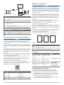
Connector View
POWER Power cable connection
NETWORK Garmin Marine Network
HDMI IN HDMI
®
in
HDMI OUT HDMI out to connect the chartplotter to a monitor.
Required for device functionality.
CVBS IN Composite video in
Status LED
Power ground
Power button
NMEA 0183 NMEA
®
0183 and audio out
USB HOST Micro-USB output for connecting a touchscreen monitor
USB OTG Micro-USB input from compatible Garmin card reader
1
,
computer, or other supported USB accessory
NMEA 2000 NMEA 2000
®
network
J1939 J1939 network
Tools Needed
• Drill
• Drill bits appropriate for the surface and hardware (3.2 mm
(
1
/
8
in.) drill bit for included screws)
• Phillips screwdriver
• Pencil
Mounting Considerations
NOTICE
This device should be mounted in a location that is not exposed
to extreme temperatures or conditions. The temperature range
for this device is listed in the product specifications. Extended
exposure to temperatures exceeding the specified temperature
range, in storage or operating conditions, may cause device
failure. Extreme-temperature-induced damage and related
consequences are not covered by the warranty.
• You must mount the device in a location where it will not be
submerged.
• You must mount the device in a location with adequate
ventilation where it will not be exposed to extreme
temperatures.
• You must mount the device at least 2.54 cm (1 in.) from
cables and other potential sources of interference.
• You must mount the device in a location that allows room for
the routing and connection of all cables.
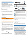
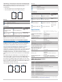
Mounting the GPSMAP 8700 Black Box Device
NOTICE
If you are mounting the device in fiberglass, when drilling the
pilot holes, use a countersink bit to drill a clearance counterbore
1
Only compatible Garmin card readers recommended. Third-party card readers
are not guaranteed to be fully compatible.
GUID-0E7D71DD-265C-4A81-9C9D-474AAB4BB516 v2November 2020

through only the top gel-coat layer. This will help to avoid
cracking in the gel-coat layer when the screws are tightened.
NOTE: Screws are included with the device, but they may not
be suitable for the mounting surface.
Before you mount the device, you must select a mounting
location, and determine what screws and other mounting
hardware are needed for the surface.
1
Place the black box device in the mounting location, and
mark the location of the pilot holes.
2
Drill a pilot hole for one corner of the device.
3
Loosely fasten the device to the mounting surface with one
corner, and examine the other three pilot-hole marks.
4
Mark new pilot-hole locations if necessary, and remove the
device from the mounting surface.
5
Drill the remaining pilot holes.
6
Secure the device to the mounting location.
Connection Considerations
When connecting this device to power and to other Garmin
devices, you should observe these considerations.
• The power and ground connections to the battery must be
checked to make sure they are secured and cannot become
loose.
• The cables may be packaged without the locking rings
installed. The cables should be routed before the locking
rings are installed.
• After installing a locking ring on a cable, you should make
sure the ring is securely connected and the o-ring is in place
so the power or data connection remains secure.
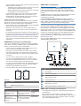
Connecting to Power
WARNING
When connecting the power cable, do not remove the in-line
fuse holder. To prevent the possibility of injury or product
damage caused by fire or overheating, the appropriate fuse
must be in place as indicated in the product specifications. In
addition, connecting the power cable without the appropriate
fuse in place voids the product warranty.
You should connect the red wire to the same battery through the
ignition or another manual switch to turn the device on and off.
1
Route the power cable between the power source and the
device.
2
Connect the red power wire to the ignition or another manual
switch, and connect the switch to the positive (+) battery
terminal if necessary.
3
Connect the black wire to the negative (-) battery terminal or
to ground.
4
Connect the power cable to the device, and turn the locking
ring clockwise to tighten it.
Additional Grounding Consideration
This device should not need additional chassis grounding in
most installation situations. If you experience interference, you
can use the grounding screw on the housing to connect the
device to the water ground of the boat to help avoid the
interference.
Power Cable Extensions
If necessary, the power cable can be extended using the
appropriate wire gauge for the length of the extension.
Item Description
Fuse
Battery
6 ft. (1.8 m) no extension
Item Description
Splice
• 10 AWG (5.26 mm²) extension wire, up to 15 ft. (4.6 m)
• 8 AWG (8.36 mm²) extension wire, up to 23 ft. (7 m)
• 6 AWG (13.29 mm²) extension wire, up to 36 ft. (11 m)
Fuse
8 in. (20.3 cm)
Battery
8 in. (20.3 cm)
36 ft. (11 m) maximum extension
Power Considerations
While you can turn the device on and off using the power key,
the device will likely not be easily accessible to do so. You
should consider connecting a switch or one of the following to
turn the GPSMAP 8700 device on and off:
• A GRID
™
device
NOTE: A GRID 20 device will not turn the GPSMAP 8700
device on or off. Using the power key on the GRID 20 device
will place the GPSMAP 8700 device into sleep mode.
• Another Garmin chartplotter
• A GMM
™
monitor
When power is applied to the GPSMAP 8700 device, the device
will turn on. You cannot disable the auto power on feature.
Garmin Marine Network Considerations
NOTICE
A Garmin Marine Network PoE Isolation Coupler
(010-10580-10) must be used when connecting any third-party
device, such as a FLIR
®
camera, to a Garmin Marine Network.
Connecting a Power over Ethernet (PoE) device directly to a
Garmin Marine Network chartplotter damages the Garmin
chartplotter and may damage the PoE device. Connecting any
third-party device directly to a Garmin Marine Network
chartplotter will cause abnormal behavior on the Garmin
devices, including the devices not properly turning off or the
software becoming inoperable.
This device can connect to additional Garmin Marine Network
devices to share data such as radar, sonar, and detailed
mapping. When connecting Garmin Marine Network devices to
this device, observe these considerations.
• All devices connected to the Garmin Marine Network must be
connected to the same ground. If multiple power sources are
used for Garmin Marine Network devices, you must tie all
ground connections from all power supplies together using a
low resistance connection or tie them to a common ground
bus bar, if available.
2

• A Garmin Marine Network cable must be used for all Garmin
Marine Network connections.
◦ Third-party CAT5 cable and RJ45 connectors must not be
used for Garmin Marine Network connections.
◦ Additional Garmin Marine Network cables and connectors
are available from your Garmin dealer.
• The NETWORK ports on the device each act as a network
switch. Any compatible device can be connected to any
NETWORK port to share data with all devices on the boat
connected by a Garmin Marine Network cable.
Station Connection Considerations
This device can be set up in conjunction with other compatible
Garmin devices to work together as a station. When planning
stations on your boat, observe these considerations.
• Devices earlier than the GPSMAP 8000 series and GPSMAP
8500 series cannot be used in a station.
• Although it is not necessary, it is recommended that you
install all of the devices you plan to use in one station near
each other.
• No special connections are necessary to create a station, as
long as all of the devices are connected to the Garmin Marine
Network (Garmin Marine Network Considerations, page 2).
• Stations are created and modified using the device software.
See the owner's manual provided with the device for more
information.
GMM Monitor Connection Considerations
You can use a GMM monitor to view and control the GPSMAP
8700. When connecting a GMM monitor to the GPSMAP 8700
device, you must observe these considerations.
• The touchscreen functionality of the GMM monitor can be
used to control one GPSMAP 8700 device.
• Although it is recommended to use Garmin DVI-D cables,
high-quality third-party DVI-D cables may be used. Before
you route a DVI-D cable, you should connect all devices to it
for testing.
• You must use an HDMI to DVI-D cable or adapter.
• You must connect the GMM monitor to the same power
source as the GPSMAP 8700 device. If this is not possible,
you must connect the devices to the same ground.
• You must connect the GMM monitor to a NETWORK port on
the GPSMAP 8700 device or to the same Garmin Marine
Network as the GPSMAP 8700 device.
• The touch data is sent over the Garmin Marine Network.
Devices
Item Device
GPSMAP chartplotter
GMM touchscreen monitor
Connections
From To Cable
Chartplotter's HDMI
OUT port
GMM monitor's MAIN DVI
VIDEO IN port
DVI-D cable with
an HDMI
adapter
GMM monitor's
GARMIN PROCESSOR
BOX port
Chartplotter's NETWORK
port or the Garmin Marine
Network
Garmin Marine
Network Cable
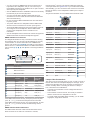
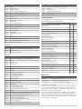
NMEA 2000 Considerations
NOTICE
If you are connecting to an existing NMEA 2000 network,
identify the NMEA 2000 power cable. Only one NMEA 2000
power cable is required for the NMEA 2000 network to operate
properly.
A NMEA 2000 Power Isolator (010-11580-00) should be used in
installations where the existing NMEA 2000 network
manufacturer is unknown.
If you are installing a NMEA 2000 power cable, you must
connect it to the boat ignition switch or through another in-line
switch. NMEA 2000 devices will drain your battery if the NMEA
2000 power cable is connected to the battery directly.
This device can connect to a NMEA 2000 network on your boat
to share data from NMEA 2000 compatible devices such as a
GPS antenna or a VHF radio. The included NMEA 2000 cables
and connectors allow you to connect the device to your existing
NMEA 2000 network. If you do not have an existing NMEA 2000
network you can create a basic one using cables from Garmin.
If you are unfamiliar with NMEA 2000, you should read the
Technical Reference for NMEA 2000 Products at garmin.com
/manuals/nmea_2000.
The port labeled NMEA 2000 is used to connect the device to a
standard NMEA 2000 network.
Item Description
NMEA 2000 compatible Garmin device
GPS antenna
Ignition or in-line switch
NMEA 2000 power cable
NMEA 2000 drop cable
12 Vdc power source
NMEA 2000 terminator or backbone cable
NMEA 2000 T-connector
NMEA 2000 terminator or backbone cable
NMEA 0183 Connection Considerations
• The chartplotter provides one Tx (transmit) port and one Rx
(receive) port.
• Each port has 2 wires, labeled A and B according to the
NMEA 0183 convention. The corresponding A and B wires of
each internal port should be connected to the A (+) and B (-)
wires of the NMEA 0183 device.
3

• You can connect one NMEA 0183 device to the Rx port to
input data to this chartplotter, and you can connect up to
three NMEA 0183 devices in parallel to the Tx port to receive
data output by this chartplotter.
• See the NMEA 0183 device installation instructions to identify
the transmit (Tx) and receive (Rx) wires.
• You must use 28 AWG, shielded, twisted-pair wiring for
extended runs of wire. Solder all connections and seal them
with heat-shrink tubing.
• Do not connect the NMEA 0183 data wires from this device
to power ground.
• The power cable from the chartplotter and the NMEA 0183
devices must be connected to a common power ground.
• The internal NMEA 0183 ports and communication protocols
are configured on the chartplotter. See the NMEA 0183
section of the chartplotter owner's manual for more
information.
• See the chartplotter owner's manual for a list of the approved
NMEA 0183 sentences that the chartplotter supports.
NMEA 0183 Device Connections
This diagram illustrates two-way connections for both sending
and receiving data. You can also use this diagram for one-way
communication. To receive information from a NMEA 0183
device, refer to items , , , , and when connecting the
Garmin device. To transmit information to a NMEA 0183 device,
refer to items , , , , and when connecting the Garmin
device.
Item Description
Power source
Power cable
NMEA 0183 device
NMEA 0183 cable
Item Garmin Wire
Function
Garmin Wire
Color
NMEA 0183
Device Wire
Function
Power Red Power
Power ground Black Power ground
Data ground Black Data ground
Rx/A (In +) White/orange Tx/A (Out +)
Rx/B (In -) White Tx/B (Out -)
Tx/A (Out +) Gray Rx/A (In +)
Tx/B (Out -) Pink Rx/B (In -)
If the NMEA 0183 device has only one input (receive, Rx) wire
(no A, B, +, or -), you must leave the pink wire unconnected.
If the NMEA 0183 device has only one output (transmit, Tx) wire
(no A, B, +, or -), you must connect the white/orange wire to
ground.
NMEA 0183 with Audio Cable Pinout
The NMEA 0183 with audio cable includes bare wires and an
RCA connector for an audio out connection to a stereo,
including Fusion
®
stereos. This optional cable (010-12390-21)
can be purchased from garmin.com or your local Garmin dealer.
After installing, you can connect the RCA connector to the AUX
input of the stereo, so the chartplotter's HDMI input is output to
the stereo.
This pinout information is for the NMEA 0183 with audio cable.
Port Wire Function Wire Color Pin Number
Input port 1 Rx/A (In +) White
Input port 1 Rx/B (In -) White/orange
Output port 1 Tx/A (Out +) Gray
Output port 1 Tx/B (Out -) Pink
Input port 2 Rx/A (In +) Brown
Input port 2 Rx/B (In -) White/brown
Output port 2 Tx/A (Out +) Blue
Output port 2 Tx/B (Out -) White/blue
Input port 3 Rx/A (In +) Violet
Input port 3 Rx/B (In -) White/violet
Input port 4 Rx/A (In +) White/black
Input port 4 Rx/B (In -) Red/white
N/A Audio Common Blue/red
N/A Audio Right Channel Red
N/A Audio Left Channel White
N/A Alarm Yellow
N/A Accessory on Orange
N/A Ground (shield) Black
N/A Spare N/A
Lamp or Horn Connections
The device can be used with a lamp, a horn, or both, to sound or
flash an alert when the chartplotter displays a message. This is
optional, and the alarm wire is not necessary for the device to
function normally. When connecting the device to a lamp or
horn, observe these considerations.
• The alarm circuit switches to a low-voltage state when the
alarm sounds.
• The maximum current is 100 mA, and a relay is needed to
limit the current from the chartplotter to 100 mA.
• To toggle visual and audible alerts manually, you can install
single-pole, single-throw switches.
4

Item Description
Power source
Power cable
Horn
Lamp
NMEA 0183 cable
Relay (100 mA coil current)
Toggle switches to enable and disable lamp or horn alerts
Item Wire Color Wire Function
Red Power
Black Ground
Yellow Alarm
J1939 Engine Network Connection Considerations
NOTICE
You must use a Garmin GPSMAP J1939 accessory cable when
connecting the chartplotter to the J1939 engine network to
prevent corrosion due to moisture. Using a different cable voids
your warranty.
If you have an existing engine network on your boat, it should
already be connected to power. Do not add any additional power
supply.
This chartplotter can connect to an engine network on your boat
to read data from compatible devices such as certain engines.
The engine network follows a standard and uses proprietary
messages.
You should connect only one chartplotter to one engine network.
Connecting more than one chartplotter to one engine network
may result in unexpected behavior.
The port labeled J1939 is used to connect the device to the
existing engine network. You must route the cable within 6 m
(20 ft.) of the engine network backbone.
The Garmin GPSMAP J1939 accessory cable requires
connection to a power source and proper termination. For more
information on connecting to your engine network, see the
manufacturer's engine documentation.
Pin Wire Color Description
Bare Shield
Red Power, positive
Black Power, negative
White CAN High
Blue CAN Low
HDMI Video Considerations
NOTICE
To prevent corrosion due to moisture, you must use Garmin
GPSMAP accessory cables when connecting the chartplotter to
the video source or display. Do not connect a media player stick
directly into the back of the chartplotter. Using different cables or
connecting a media player stick into the back of the chartplotter
voids your warranty.
The GPSMAP 8700 chartplotter allows video input from HDMI
video sources, such as a Chromecast
™
device. You cannot view
protected HDMI content (HDCP content), though. Check the
video source's manual to verify that HDCP can be turned off for
the source.
HDMI video is shared across the Garmin Marine Network, but it
is not shared across the NMEA 2000 network.
Through the HDMI OUT port, you can display the video on
screen, such as a television or monitor.
The Garmin GPSMAP HDMI accessory cable is 4.5 m (15 ft)
long. If you need a longer cable, you should use an active HDMI
cable only. You need an HDMI coupler to connect the two HDMI
cables.
You need a Garmin GPSMAP USB OTG adapter cable to power
a media player stick. The USB HOST port can supply up to
2.5 W to power a media player stick.
You must make all cable connections in a dry environment.
Devices
Item Device
HDMI source, such as a Chromecast device
GPSMAP chartplotter
Monitor, such as a computer or television
Connections
From To Cable
HDMI source's HDMI
OUT port
Chartplotter's HDMI IN
port
Garmin HDMI Cable
Chartplotter's HDMI
OUT port
Monitor's HDMI IN
port
Garmin HDMI Cable
Chartplotter's USB OTG
or USB HOST port
HDMI source's USB
HOST port
GPSMAP USB OTG
adapter cable to
power the HDMI
source, if possible
(2.5 W maximum)
Composite Video Considerations
This chartplotter allows video input from composite video
sources using the port labeled CVBS IN. When connecting
composite video, you should observe these considerations.
• The CVBS IN port uses a BNC connector. You can use a
BNC to RCA adapter to connect a composite-video source
with RCA connectors to the CVBS IN port.
• Video is shared across the Garmin Marine Network, but it is
not shared across the NMEA 2000 network.
5

Third-Party Touchscreen Connection Considerations
When connecting a third-party touchscreen to view and control
the GPSMAP 8700 device, you must observe these
considerations.
• The video data is sent over the HDMI connection.
• The touch data is sent over the USB connection.
Devices
Item Device
GPSMAP chartplotter
Third-party touchscreen monitor
Connections
From To Cable
Chartplotter's HDMI
OUT port
Monitor's HDMI IN port
Garmin HDMI
Cable
Monitor's USB port Chartplotter's USB HOST
port
Garmin OTG
Adapter Cable
NOTE: If the monitor is not a touchscreen, you should install a
GRID remote control (not a GRID 20 remote control).
Touchscreen Controls for a Connected Computer
NOTICE
To prevent corrosion due to moisture, you must use Garmin
GPSMAP accessory cables when connecting the chartplotter to
the computer. Using different cables voids your warranty.
You can connect the chartplotter to a computer to see the
computer screen and to control the computer using a
touchscreen. To see the computer screen, you must connect the
computer to the HDMI IN port and connect the touchscreen to
the HDMI OUT port. To control the computer using the
chartplotter touchscreen, you must connect the computer to the
USB OTG port and connect the touchscreen to the USB HOST
port.
The HDMI Cable (010-12390-20) is 4.5 m (15 ft) long. If you
need a longer cable, you should use an active HDMI cable only.
You need an HDMI coupler to connect the two HDMI cables.
The Garmin OTG Adapter Cable (010-12390-11) is 1.8 m (6 ft)
long and the Garmin USB Cable (010-12390-10) is 4.5 m (15 ft)
long. If you need a longer cable, you should use a USB hub or
USB repeater extension cable only.
You must make all cable connections in a dry environment.
Devices
Item Device
Computer
GPSMAP chartplotter
Touchscreen monitor
Connections
From To Cable
Computer's HDMI OUT
port
Chartplotter's HDMI IN
port
Garmin HDMI
Cable
Chartplotter's HDMI OUT
port
Monitor's HDMI IN port
Garmin HDMI
Cable
Monitor's USB port Chartplotter's USB HOST
port
Garmin OTG
Adapter Cable
Chartplotter's USB OTG
port
Computer's USB HOST
port
Garmin USB
Cable
Specifications
Dimensions (W × H × D) 38.3 × 19.8 × 4.7 cm (15
1
/
8
× 7
13
/
16
×
1
7
/
8
in.)
Clearance on front of device 8.6 cm (3
3
/
8
in.)
Weight 1.39 kg (3.06 lb.)
Compass-safe distance 2.54 cm (1 in.)
Temperature range From -15° to 55°C (from 5° to 131°F)
Material Polycarbonate plastic and die-cast
aluminum
Water rating IEC 60529 IPX7
1
Fuse 10 A, 42 V fast-acting
Input voltage From 10 to 32 Vdc
Max. power usage at 10 Vdc 40.1 W
Typical current draw at 12 Vdc 1.5 A
Max. current draw at 12 Vdc 6.0 A
NMEA 2000 LEN @ 9 Vdc 2
NMEA 2000 draw 75 mA max.
HTML integration Compatible with OneHelm
™
integration
Memory card External card reader required (not
included)
Wireless frequency and
protocols
Wi‑Fi
®
and ANT
®
technologies
2.4 GHz @ 14.15 dBm maximum
NMEA 2000 PGN Information
Transmit and Receive
PGN Description
059392 ISO acknowledgment
059904 ISO request
060160 ISO transport protocol: Data transfer
060416 ISO transport protocol: Connection management
060928 ISO address claimed
065240 Commanded address
126208 Request group function
126996 Product information
126998 Configuration information
127237 Heading/track control
1
The device withstands incidental exposure to water of up to 1 m for up to 30 min.
For more information, go to www.garmin.com/waterrating.
6

PGN Description
127245 Rudder
127250 Vessel heading
127258 Magnetic variance
127488 Engine parameters: Rapid update
127489 Engine parameters: Dynamic
127493 Transmission parameters: Dynamic
127505 Fluid level
127508 Battery status
128259 Speed: Water referenced
128267 Water depth
129025 Position: Rapid update
129026 COG and SOG: Rapid update
129029 GNSS position data
129283 Cross track error
129284 Navigation data
129539 GNSS DOPs
129540 GNSS satellites in view
130060 Label
130306 Wind data
130310 Environmental parameters (obsolete)
130311 Environmental parameters (obsolete)
130312 Temperature (obsolete)
Transmit
PGN Description
126464 Transmit and receive PGN list group function
126984 Alert Response
127497 Trip parameters: Engine
Receive
PGN Description
065030 Generator average basic AC quantities (GAAC)
126983 Alert
126985 Alert text
126987 Alert threshold
126988 Alert value
126992 System time
127251 Rate of turn
127257 Attitude
127498 Engine parameters: Static
127503 AC input status (obsolete)
127504 AC output status (obsolete)
127506 DC detailed status
127507 Charger status
127509 Inverter status
128000 Nautical leeway angle
128275 Distance log
129038 AIS class A position report
129039 AIS class B position report
129040 AIS class B extended position report
129044 Datum
129285 Navigation: Route, waypoint information
129794 AIS class A static and voyage related data
129798 AIS SAR aircraft position report
129799 Radio frequency/mode/power
129802 AIS safety-related broadcast message
129808 DSC call Information
129809 AIS class B "CS" static data report, part A
PGN Description
129810 AIS class B "CS" static data report, part B
130313 Humidity
130314 Actual pressure
130316 Temperature: Extended range
130576 Trim tab status
130577 Direction data
J1939 Information
The chartplotter can receive J1939 sentences. The chartplotter
cannot transmit over the J1939 network.
Description PGN SPN
Engine percent load at current speed 61443 92
Engine speed 61444 190
Engine manifold exhaust gas temperature - right manifold 65031 2433
Engine manifold exhaust gas temperature - left manifold 65031 2434
Engine auxiliary coolant 65172
Active diagnostic trouble codes 65226
Vehicle distance 65248
Water in fuel indicator 65279
Engine wait to start lamp 65252 1081
Engine over speed test 65252 2812
Engine air shutoff command status 65252 2813
Engine alarm output command status 65252 2814
Engine total hours of operation 65253 247
Navigation-based vehicle speed 65256 517
Engine fuel temperature 1 65262 174
Engine oil temperature 1 65262 175
Engine fuel delivery pressure 65263 94
Engine oil pressure 65263 100
Engine coolant pressure 65263 109
Engine coolant temperature 65263 110
Engine coolant level 65263 111
Engine fuel rate 65266 183
Engine average fuel economy 65266 185
Engine intake manifold #1 pressure 65270 102
Battery potential / power input 1 65271 168
Transmission oil temperature 65272 177
Transmission oil pressure 65272 127
Fuel level 65276 96
Engine oil filter differential pressure 65276 969
Status LED
LED Activity Status
Solid red The device is turning on.
Flashing green The device is operating normally.
Flashing orange The device software is being updated.
© 2019 Garmin Ltd. or its subsidiaries
Garmin
®
, the Garmin logo, ActiveCaptain
®
, ANT
®
, and Fusion
®
are trademarks of Garmin
Ltd. or its subsidiaries, registered in the USA and other countries. GMM
™
, GRID
™
, and
OneHelm
™
are trademarks of Garmin Ltd. or its subsidiaries. These trademarks may not
be used without the express permission of Garmin.
FLIR
®
is a registered trademark of FLIR Systems, Inc. HDMI
®
is a registered trademark of
HDMI Licensing, LLC. NMEA
®
, NMEA 2000
®
, and the NMEA 2000 logo are registered
trademarks of the National Marine Electronics Association.
Wi‑Fi
®
is a registered mark of
Wi-Fi Alliance Corporation. Windows
®
is a registered trademark of Microsoft Corporation
in the United States and other countries.
7

© 2019 Garmin Ltd. or its subsidiaries
support.garmin.com
-
 1
1
-
 2
2
-
 3
3
-
 4
4
-
 5
5
-
 6
6
-
 7
7
-
 8
8


Garmin Black box GPSMAP 8700 Owner's manual
- Category
- Car video systems
- Type
- Owner's manual
Ask a question and I''ll find the answer in the document
Finding information in a document is now easier with AI
Related papers
-
Garmin GPSMAP® 8700 Black Box Installation guide
-
Garmin GPSMAP® 8424 MFD Owner's manual
-
Garmin GPSMAP User manual
-
Garmin 190-01178-00 User manual
-
Garmin AiS 300 Blackbox Receiver Installation guide
-
Garmin GPS 19x HVS (NMEA 0183) Installation guide
-
Garmin GPS 19x NMEA 2000® Installation guide
-
-
Garmin GRID™ 20 Installation guide
-
Garmin GC 100 tradlos kamera Operating instructions
Other documents
-
Standard Horizon Wiring Garmin GPSMap 640 Owner's manual
-
Wet Sounds WS-NMEA-TR Owner's manual
-
Digitus DK-300309-002-S Datasheet
-
 Volvo Penta Glass Cockpit Owner's manual
-
Fusion MS-CBUSB3.5 Installation guide
-
Simrad IS42J Operating instructions
-
-
FLIR M-Series Owner's manual
-
Humminbird Dual NMEA Y-CABLE Installation guide
-
Airmar GPS & Heading Sensors Owner's manual
