Garmin GPS 19x NMEA 2000® Installation guide

Type
Installation guide

This manual is also suitable for

GPS 19X NMEA 2000
®
INSTALLATION
INSTRUCTIONS
Important Safety Information
CAUTION
To avoid possible personal injury, always wear safety goggles,
ear protection, and a dust mask when drilling, cutting, or
sanding.
NOTICE
When drilling or cutting, always check what is on the opposite
side of the surface to avoid damaging the vessel.
For the best performance and to avoid damage to your boat,
read all installation instructions before proceeding. Install the
device per these instructions. Use the appropriate fasteners,
tools, and mounts listed, which are available at most marine
dealers.
For more information, go to support.garmin.com.
Tools Needed
Drill
3.2 mm (1/8 in.) drill bit
19 mm (3/4 in.) drill bit for a pole-mount cable-hole
25 mm (1 in.) hole saw for a surface-mount cable-hole
Countersink bit for mounting on fiberglass
Screws for under-deck mounting
Screwdriver, appropriate for the screw type
Marine sealant (optional)
Additional NMEA 2000 network components as needed
Mounting the Antenna
Antenna Mounting Considerations
CAUTION
Do not install or store the antenna near strong magnets,
including speakers. A strong magnetic field can damage the
antenna.
You can mount the antenna on a flat surface or attach it to a
standard 1 in. OD, 14 threads per inch, pipe-threaded pole (not
included). You can route the cable outside of the pole or through
the pole. For best performance, consider these guidelines when
selecting the antenna mounting location.
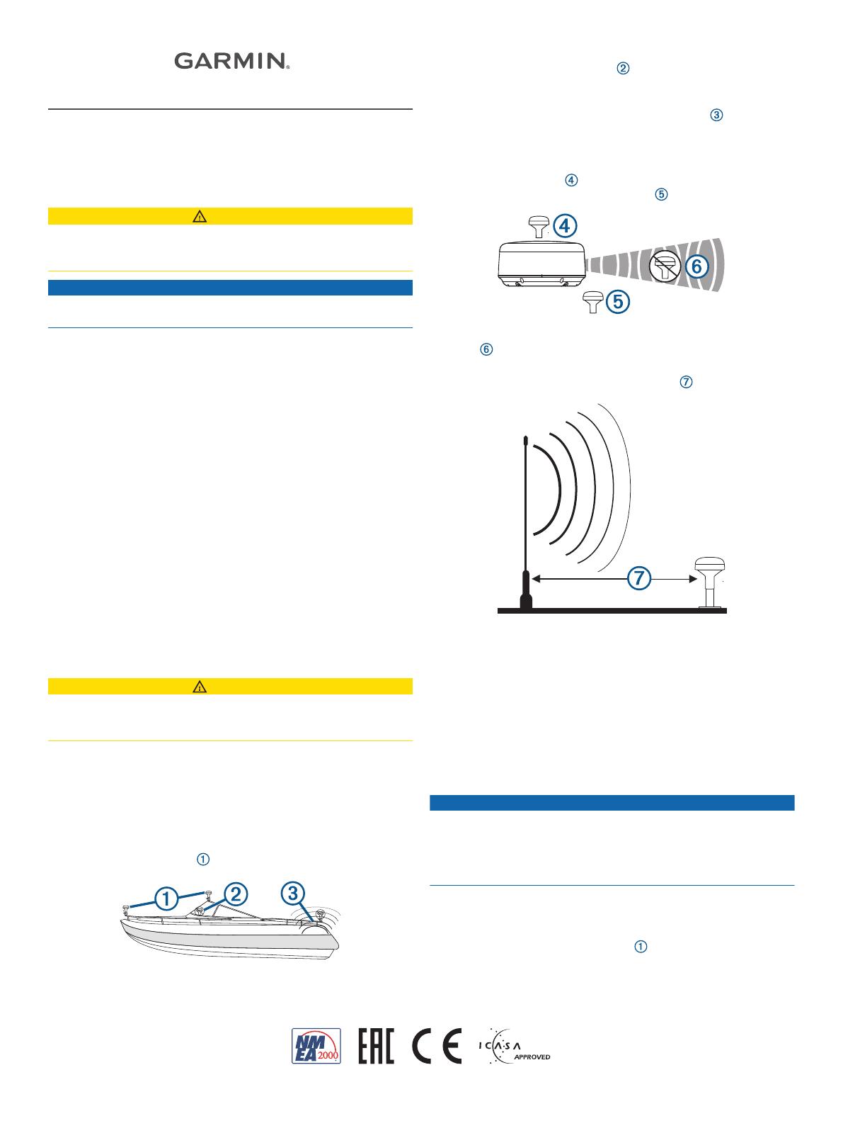
To ensure the best reception, the antenna should be
mounted in a location that has a clear, unobstructed view of
the sky in all directions .
The antenna should not be mounted where it is shaded by
the superstructure of the boat , a radome antenna, or the
mast.
The antenna should not be mounted near the engine or other
sources of Electromagnetic Interference (EMI) .
The antenna should not be mounted near known ferrous
metal objects such as a toolbox or compass.
If a radar is present, the antenna should be mounted above
the path of the radar . If necessary, the antenna may be
mounted below the path of the radar .
The antenna should not be mounted directly in the path of the
radar .
The antenna should not be mounted within 1 m (3 ft.) of a
VHF radio antenna or the path of a radar .
Testing the Mounting Location
1
Temporarily secure the antenna in the preferred mounting
location and test it for correct operation.
2
If you experience interference with other electronics, move
the antenna to a different location, and test it again.
3
Repeat steps 1–2 until you observe full or acceptable signal
strength.
4
Permanently mount the antenna.
Surface Mounting the Antenna
NOTICE
If you are mounting the bracket on fiberglass with screws, it is
recommended to use a countersink bit to drill a clearance
counterbore through only the top gel-coat layer. This will help to
avoid cracking in the gel-coat layer when the screws are
tightened.
Before you permanently mount the antenna, you must test the
mounting location for correct operation (Testing the Mounting
Location, page 1).
1
Using the surface-mount bracket as your mounting
template, mark the three pilot-hole locations and trace the
cable-hole in the center of the bracket.
TA-2013/784
GUID-512A740F-7146-4626-9C08-48DB06A8A4EE v1January 2021
2
Set the surface-mount bracket aside.
Do not drill through the bracket.
3
Drill the three 3.2 mm (
1
/
8
in.) pilot holes.
4
Drill the 25 mm (1 in.) cable hole in the center.
5
Use the included M4 screws to secure the surface-mount
bracket to the mounting surface.
6
Route the cable through the center hole, and connect it to
the antenna.
7
Verify the large gasket is in place on the bottom of the
antenna, place the antenna on the surface-mount bracket,
and twist it clockwise to lock it in place.
8
Secure the antenna to the mounting bracket with the included
M3 screw .
9
Route the cable away from sources of electronic interference.
Mounting the Antenna on a Pole
Mounting the Antenna with the Cable Routed Outside the
Pole
Before you permanently mount the antenna, you must test the
mounting location for correct operation (Testing the Mounting
Location, page 1).
1
Route the cable through the pole-mount adapter , and
place the cable in the vertical slot along the base of the
pole-mount adapter.
2
Screw the pole-mount adapter onto a standard 1 in. OD, 14
threads per inch, pipe-threaded pole (not included).
Do not overtighten the adapter on the pole.
3
Connect the cable to the antenna.
4
Place the antenna on the pole-mount adapter and twist it
clockwise to lock it in place.
5
Secure the antenna to the adapter with the included M3 set
screw .
6
With the antenna installed on the pole mount, fill the
remaining gap in the vertical cable slot with a marine sealant
(optional).
7
Attach the pole to the boat if it is not already attached.
8
Route the cable away from sources of electronic interference.
Mounting the Antenna with the Cable Routed Through the
Pole
Before you permanently mount the antenna, you must test the
mounting location for correct operation (Testing the Mounting
Location, page 1).
1
Position a standard 1 in. OD, 14 threads per inch, pipe-
threaded pole (not included) in the selected location, and
mark the approximate center of the pole.
2
Drill a hole using a 19 mm (
3
/
4
in.) drill bit for the cable to
pass through.
3
Fasten the pole to the boat.
4
Thread the pole-mount adapter onto the pole.
Do not overtighten the adapter.
5
Route the cable through the pole and connect it to the
antenna.
6
Place the antenna on the pole-mount adapter and twist it
clockwise to lock it in place.
7
Secure the antenna to the adapter with the included M3 set
screw .
8
With the antenna installed on the pole mount, fill the vertical
cable slot with a marine sealant (optional).
9
Route the cable away from sources of electronic interference.
Mounting the Antenna Under a Surface
NOTICE
Verify that the supplied screws will not penetrate the surface
before you install the under-deck mounting bracket. If the
supplied screws are too long, use surface-appropriate screws
instead.
Because the antenna cannot acquire signals through metal, it
must be mounted under a fiberglass surface only.
1
Determine and test the location under a fiberglass surface
where you want to mount the antenna (Testing the Mounting
Location, page 1).
2
2
Place the adhesive pads on the under-deck mounting
bracket .
3
Place the antenna in the under-deck mounting bracket.
4
Adhere the under-deck mounting bracket to the mounting
surface.
5
Secure the under-deck mounting bracket to the mounting
surface with screws.
6
Connect the cable to the antenna .
7
Route the cable away from sources of electronic interference.
Connecting the Antenna
NMEA 2000 Network Connection
If you do not have an existing NMEA 2000 network, you must
install a NMEA 2000 network on your boat. For more information
on NMEA 2000, go to garmin.com/manuals/nmea_2000.
The antenna is packaged with a NMEA 2000 T-connector and a
NMEA 2000 drop cable. You will use these two components to
connect the antenna to your existing NMEA 2000 network.
If the included drop cable is not long enough, you can add a
drop cable extension up to 4 m (13 ft.). If more cable is needed,
add an extension to your NMEA 2000 backbone, based on the
NMEA 2000 guidelines.
Antenna
NMEA 2000 drop cable
NMEA 2000 T-connector
NMEA 2000 backbone
Antenna Configuration
To access the NMEA 2000 configuration menu on your Garmin
®
device, consult the documentation provided with your device.
While viewing the NMEA 2000 configuration menu on your
Garmin device, you must select the antenna, then select
Review to change these settings.
WAAS/EGNOS: Enables WAAS (Wide Area Augmentation
System in North America) and EGNOS (European
Geostationary Navigation Overlay Service) to provide more
accurate position information.
Speed Filter: Enables data averaging to provide smoother
position updates, reducing unnecessary drift-alarm triggers.
You can enable it when stationary or for lower speeds when it
is most helpful, or disable it for higher speeds.
Auto Locate: Allows you to clear cached satellite data, forcing
the device to acquire new data. This can be helpful if you
have moved the boat many miles without using the antenna.
GLONASS: Enables GLONASS (Global Navigation Satellite
System in Russia) satellites.
Factory Defaults: Allows you to reset the antenna to factory
default. You will lose all custom configuration settings.
Cleaning the Outer Casing
NOTICE
Avoid chemical cleaners and solvents that can damage plastic
components.
1
Clean the outer casing of the device using a cloth dampened
with a mild detergent solution.
2
Wipe the device dry.
Appendix
Software Update
You must update the Garmin chartplotter software when you
install this device. For instructions on updating the software, see
your chartplotter owner's manual at support.garmin.com.
Specifications
Dimensions (diameter x height) 91.6 × 49.5 mm ( 3
19
/
32
× 1
15
/
16
in.)
Weight 201 g (7.1 oz.)
NMEA 2000 drop cable length 6 m (19 ft., 8 in.)
Temperature range From -30° to 80°C (from -22° to 176°F)
Case material Fully gasketed, high-impact plastic
alloy
Water rating IEC 60529 IPX7
1
Compass-safe distance 150 mm (5.9 in.)
Power input source 9 to 16 Vdc, unregulated
Input current 40 mA @ 12 Vdc
NMEA 2000 LEN @ 9 Vdc 2 (100 mA)
NMEA 2000 draw 40 mA @ 12 Vdc
NMEA 2000 PGN Information
Transmit
059392 ISO acknowledgment
060928 ISO address claimed
126208 Request group function
126464 Transmit and receive PGN list
group function
126992 System time
126996 Product information
129025 Position: Rapid update
129026 COG and SOG: Rapid update
129029 GNSS position data
129539 GNSS DOPs
129540 GNSS Sats in view
1
The device withstands incidental exposure to water of up to 1 m for up to 30 min.
For more information, go to www.garmin.com/waterrating.
3
Receive
059392 ISO acknowledgment
059904 ISO request
060928 ISO address claimed
126208 Request group function
Battery Notice
NOTICE
Contact your local waste disposal department to dispose of the
device/batteries in accordance with applicable local laws and
regulations.
Declaration of Conformity
Hereby, Garmin declares that this product is in compliance with
the Directive 2014/53/EU. The full text of the EU declaration of
conformity is available at the following internet address:
garmin.com/compliance.
Innovation, Science and Economic Development
Canada Compliance
This device contains licence-exempt transmitter(s)/receiver(s)
that comply with Innovation, Science and Economic
Development Canada's licence-exempt RSS(s). Operation is
subject to the following two conditions: (1) this device may not
cause interference, and (2) this device must accept any
interference, including interference that may cause undesired
operation of the device.
FCC Compliance
This device complies with part 15 of the FCC Rules. Operation
is subject to the following two conditions: (1) this device may not
cause harmful interference, and (2) this device must accept any
interference received, including interference that may cause
undesired operation.
This equipment has been tested and found to comply with the
limits for a Class B digital device, pursuant to part 15 of the FCC
rules. These limits are designed to provide reasonable
protection against harmful interference in a residential
installation. This equipment generates, uses, and can radiate
radio frequency energy and may cause harmful interference to
radio communications if not installed and used in accordance
with the instructions. However, there is no guarantee that
interference will not occur in a particular installation. If this
equipment does cause harmful interference to radio or television
reception, which can be determined by turning the equipment off
and on, the user is encouraged to try to correct the interference
by one of the following measures:
Reorient or relocate the receiving antenna.
Increase the separation between the equipment and the
receiver.
Connect the equipment into an outlet on a circuit different
from that to which the receiver is connected.
Consult the dealer or an experienced radio/TV technician for
help.
This product does not contain any user-serviceable parts.
Repairs should only be made by an authorized Garmin service
center. Unauthorized repairs or modifications could result in
permanent damage to the equipment, and void your warranty
and your authority to operate this device under Part 15
regulations.
Limited Warranty
The Garmin standard limited warranty applies to this accessory.
For more information, go to www.garmin.com/support/warranty.
© 2012 Garmin Ltd. or its subsidiaries
Garmin
®
and the Garmin logo are trademarks of Garmin Ltd. or its subsidiaries,
registered in the USA and other countries. These trademarks may not be used without
the express permission of Garmin.
NMEA 2000
®
and the NMEA 2000 logo are registered trademarks of the National Marine
Electronics Association.
Garmin Corporation
© 2012 Garmin Ltd. or its subsidiaries
support.garmin.com
  • Page 1 1
  • Page 2 2
  • Page 3 3
  • Page 4 4

Garmin GPS 19x NMEA 2000® Installation guide

Type
Installation guide
This manual is also suitable for

Ask a question and I''ll find the answer in the document

Finding information in a document is now easier with AI