Operating and maintenance instructions
Part Number: 3-9008-701, Rev. J
January 2015
Compact Prover


Daniel customer service
Email
• Customer Service: tech.service@emersonprocess.com
• Customer Support: daniel.cst.suppor[email protected]om
• Asia-Pacific: danielap.suppor[email protected]
• Europe: DanielEMA.CST@EmersonProcess.com
Location Telephone number Fax number
North America/Latin America +1.713.467.6000 +1.713.827.4805
Daniel Customer Service +1.713.827.6314 +1.713.827.6312
USA (toll free) +1.888.356.9001 +1.713.827.3380
Asia Pacific (Republic of Singapore) +65.6777.8211 +65.6777.0947.0743
Europe (Stirling Scotland, UK) +44 (0)1786.433400 +44 (0)1786.433401
Middle East Africa (Dubai, UAE) +971 4 8118100 +971 4 8865465
Return Material Authorization (RMA)
A Return Material Authorization (RMA) number must be obtained prior to returning any equipment for any reason.
Download the RMA form from the Support Services web page by selecting the link below.
www2.emersonprocess.com/EN-US/BRANDS/DANIEL/SUPPORT-SERVICES/Pages/Support-Services.aspx?

Signal words and symbols
Pay special attention to the following signal words, safety alert symbols and statements:
Important
Important is a statement the user needs to know and consider.
Tip
Tip provides information or suggestions for improved efficiency or best results.
Note
Note is a “general by-the-way” content not essential to the main flow of information.
This is a safety alert symbol. It is used to alert you to potential physical injury hazards. Obey
all safety messages that follow this syLmbol to avoid possible injury or death.
Safety alert symbol
Danger indicates a hazardous situation which, if not avoided, will result in death or serious
injury.
Warning indicates a hazardous situation which, if not avoided, could result in death or serious
injury.
Caution indicates a hazardous situation which, if not avoided, could result in minor or
moderate injury.
Caution indicates a hazardous situation which, if not avoided, could result in minor or
moderate injury.

Important safety instructions
Daniel Measurement and Control, Inc. (Daniel) designs, manufactures and tests products to
function within specific conditions. Because these products are sophisticated technical
instruments, it is important that the owner and operation personnel strictly adhere both to the
information printed on the product and to all instructions provided in this manual prior to
installation, operation, and maintenance.
Daniel also urges you to integrate this manual into your training and safety program.
BE SURE ALL PERSONNEL READ AND FOLLOW THE INSTRUCTIONS IN THIS MANUAL AND ALL
NOTICES AND PRODUCT WARNINGS.
Product owners (Purchasers):
• Use the correct product for the environment and pressures present. See technical data
or product specifications for limitations. If you are unsure, discuss your needs with your
Daniel representative.
• Inform and train all personnel in the proper installation, operation, and maintenance of
this product.
• To ensure safe and proper performance, only informed and trained personnel should
install, operate, repair and maintain this product.
• Verify that this is the correct instruction manual for your Daniel product. If this is not
the correct documentation, contact Daniel at 1-713-827-6314. You may also download
the correct manual from:
http://www.daniel.com
• Save this instruction manual for future reference.
• If you resell or transfer this product, it is your responsibility to forward this instruction
manual along with the product to the new owner or transferee.
• ALWAYS READ AND FOLLOW THE INSTALLATION, OPERATIONS, MAINTENANCE AND
TROUBLESHOOTING MANUALS AND ALL PRODUCT WARNINGS AND INSTRUCTIONS.
• Do not use this equipment for any purpose other than its intended service. This may
result in property damage and/or serious personal injury or death.
Installing, operating or maintaining a Daniel product improperly could lead to serious injury or
death from explosion or exposure to dangerous substances. To reduce this risk:
• Comply with all information on the product, in this manual, and in any local and national
codes that apply to the product.
• Do not allow untrained personnel to work with this product.
• Use Daniel parts and work procedures specified in this manual.

Product Operation Personnel:
• To prevent personal injury, personnel must follow all instructions of this manual prior to
and during operation of the product.
• Follow all warnings, cautions, and notices marked on, and supplied with, this product.
• Verify that this is the correct instruction manual for your Daniel product. If this is not
the correct documentation, contact Daniel at 1-713-827-6314. You may also download
the correct manual from:
http://www.daniel.com
• Read and understand all instructions and operating procedures for this product.
• If you do not understand an instruction, or do not feel comfortable following the
instructions, contact your Daniel representative for clarification or assistance.
• Install this product as specified in the INSTALLATION section of this manual per
applicable local and national codes.
• Follow all instructions during the installation, operation, and maintenance of this
product.
• Connect the product to the appropriate pressure and electrical sources when and
where applicable.
• Ensure that all connections to pressure and electrical sources are secure prior to and
during equipment operation.
• Use only replacement parts specified by Daniel. Unauthorized parts and procedures can
affect this product's performance, safety, and invalidate the warranty. “Look-a-like”
substitutions may result in deadly fire, explosion, release of toxic substances or
improper operation.
• Save this instruction manual for future reference.

Notice
THE CONTENTS OF THIS PUBLICATION ARE PRESENTED FOR INFORMATIONAL PURPOSES ONLY,
AND WHILE EVERY EFFORT HAS BEEN MADE TO ENSURE THEIR ACCURACY, THEY ARE NOT TO
BE CONSTRUED AS WARRANTIES OR GUARANTEES, EXPRESSED OR IMPLIED, REGARDING THE
PRODUCTS OR SERVICES DESCRIBED HEREIN OR THEIR USE OR APPLICABILITY. ALL SALES ARE
GOVERNED BY DANIEL'S TERMS AND CONDITIONS, WHICH ARE AVAILABLE UPON REQUEST. WE
RESERVE THE RIGHT TO MODIFY OR IMPROVE THE DESIGNS OR SPECIFICATIONS OF SUCH
PRODUCTS AT ANY TIME.
DANIEL DOES NOT ASSUME RESPONSIBILITY FOR THE SELECTION, USE OR MAINTENANCE OF
ANY PRODUCT. RESPONSIBILITY FOR PROPER SELECTION, USE AND MAINTENANCE OF ANY
DANIEL PRODUCT REMAINS SOLELY WITH THE PURCHASER AND END-USER.
TO THE BEST OF DANIEL'S KNOWLEDGE THE INFORMATION HEREIN IS COMPLETE AND
ACCURATE. DANIEL MAKES NO WARRANTIES, EXPRESSED OR IMPLIED, INCLUDING THE IMPLIED
WARRANTIES OF MERCHANTABILITY AND FITNESS FOR A PARTICULAR PURPOSE WITH RESPECT
TO THIS MANUAL AND, IN NO EVENT, SHALL DANIEL BE LIABLE FOR ANY INCIDENTAL, PUNITIVE,
SPECIAL OR CONSEQUENTIAL DAMAGES INCLUDING, BUT NOT LIMITED TO, LOSS OF
PRODUCTION, LOSS OF PROFITS, LOSS OF REVENUE OR USE AND COSTS INCURRED INCLUDING
WITHOUT LIMITATION FOR CAPITAL, FUEL AND POWER, AND CLAIMS OF THIRD PARTIES.
PRODUCT NAMES USED HEREIN ARE FOR MANUFACTURER OR SUPPLIER IDENTIFICATION ONLY
AND MAY BE TRADEMARKS/REGISTERED TRADEMARKS OF THESE COMPANIES.

Warranty and Limitations
1. LIMITED WARRANTY: Subject to the limitations contained in Section 2 herein, Daniel Measurement &
Control, Inc. ("Daniel") warrants that the licensed firmware embodied in the Goods will execute the
programming instructions provided by Daniel, and that the Goods manufactured by Daniel will be free from
defects in materials or workmanship under normal use and care and Services will be performed by trained
personnel using proper equipment and instrumentation for the particular Service provided. The foregoing
warranties will apply until the expiration of the applicable warranty period. Goods are warranted for twelve
(12) months from the date of initial installation or eighteen (18) months from the date of shipment by Daniel,
whichever period expires first. Consumables and Services are warranted for a period of 90 days from the date
of shipment or completion of the Services. Products purchased by Daniel from a third party for resale to Buyer
("Resale Products") shall carry only the warranty extended by the original manufacturer. Buyer agrees that
Daniel has no liability for Resale Products beyond making a reasonable commercial effort to arrange for
procurement and shipping of the Resale Products. If Buyer discovers any warranty defects and notifies Daniel
thereof in writing during the applicable warranty period, Daniel shall, at its option, correct any errors that are
found by Daniel in the firmware or Services or repair or replace F.O.B. point of manufacture that portion of the
Goods or firmware found by Daniel to be defective, or refund the purchase price of the defective portion of the
Goods/Services. All replacements or repairs necessitated by inadequate maintenance, normal wear and usage,
unsuitable power sources or environmental conditions, accident, misuse, improper installation, modification,
repair, use of unauthorized replacement parts, storage or handling, or any other cause not the fault of Daniel
are not covered by this limited warranty, and shall be at Buyer's expense. Daniel shall not be obligated to pay
any costs or charges incurred by Buyer or any other party except as may be agreed upon in writing in advance
by Daniel. All costs of dismantling, reinstallation and freight and the time and expenses of Daniel's personnel
and representatives for site travel and diagnosis under this warranty clause shall be borne by Buyer unless
accepted in writing by Daniel. Goods repaired and parts replaced by Daniel during the warranty period shall be
in warranty for the remainder of the original warranty period or ninety (90) days, whichever is longer. This
limited warranty is the only warranty made by Daniel and can be amended only in a writing signed by Daniel.
THE WARRANTIES AND REMEDIES SET FORTH ABOVE ARE EXCLUSIVE. THERE ARE NO REPRESENTATIONS OR
WARRANTIES OF ANY KIND, EXPRESS OR IMPLIED, AS TO MERCHANTABILITY, FITNESS FOR PARTICULAR
PURPOSE OR ANY OTHER MATTER WITH RESPECT TO ANY OF THE GOODS OR SERVICES. Buyer acknowledges
and agrees that corrosion or erosion of materials is not covered by this warranty.
2. LIMITATION OF REMEDY AND LIABILITY
: DANIEL SHALL NOT BE LIABLE FOR DAMAGES CAUSED BY DELAY IN
PERFORMANCE. THE REMEDIES OF BUYER SET FORTH IN THIS AGREEMENT ARE EXCLUSIVE. IN NO EVENT,
REGARDLESS OF THE FORM OF THE CLAIM OR CAUSE OF ACTION (WHETHER BASED IN CONTRACT,
INFRINGEMENT, NEGLIGENCE, STRICT LIABILITY, OTHER TORT OR OTHERWISE), SHALL DANIEL'S LIABILITY TO
BUYER AND/OR ITS CUSTOMERS EXCEED THE PRICE TO BUYER OF THE SPECIFIC GOODS MANUFACTURED OR
SERVICES PROVIDED BY DANIEL GIVING RISE TO THE CLAIM OR CAUSE OF ACTION. BUYER AGREES THAT IN NO
EVENT SHALL DANIEL'S LIABILITY TO BUYER AND/OR ITS CUSTOMERS EXTEND TO INCLUDE INCIDENTAL,
CONSEQUENTIAL OR PUNITIVE DAMAGES. THE TERM "CONSEQUENTIAL DAMAGES" SHALL INCLUDE, BUT NOT
BE LIMITED TO, LOSS OF ANTICIPATED PROFITS, REVENUE OR USE AND COSTS INCURRED INCLUDING
WITHOUT LIMITATION FOR CAPITAL, FUEL AND POWER, AND CLAIMS OF BUYER'S CUSTOMERS.

Operating and maintenance instructions Table of Contents
3-9008-701 Rev J January 2015
Table of Contents 9
Contents
Daniel customer service ................................................................................... 3
• Signal words and symbols .............................................................................. 4
• Important safety instructions ......................................................................... 5
• Notice .......................................................................................................... 7
• Warranty and Limitations ............................................................................... 8
Section 1: Introduction
1.1 General ...................................................................................................... 1
1.2 Description ................................................................................................. 1
1.3 Mechanical description ................................................................................ 2
1.4 Technical data............................................................................................. 6
Section 2: Installation and set-up
2.1 Installation ............................................................................................... 13
2.2 Set-up ...................................................................................................... 15
2.2.1 Supplying electrical power to the compact prover ....................................... 15
2.2.2 Connection of the operating computer ....................................................... 16
2.2.3 12 or 24V DC Interface Board....................................................................... 18
2.2.4 Charging the Pneumatic Spring Plenum....................................................... 21
2.3 Base volume certification ........................................................................... 23
2.4 Calibration integrity seal installation procedure .......................................... 24
Section 3: Operation
3.1 General operational theory ........................................................................ 27
3.2 Operating instructions .............................................................................. 30
Section 4: Maintenance
4.1 Seal Leak Check......................................................................................... 35
4.2 Base volume determination........................................................................ 37
4.2.1 Certification techniques............................................................................... 37
4.2.2 Water draw procedure: (Reference Figure 4-4 and notes on page 47).......... 42
4.3 Certification Data Sheet and Calculations.................................................... 49
4.3.1 Data Sheet Entries ....................................................................................... 49
4.3.2 Calculations................................................................................................. 50
4.4 Seal Replacement ...................................................................................... 52
4.4.1 Measurement Piston and Flow Tube ............................................................ 52
4.4.2 Optical Seal Support .................................................................................... 60
4.4.3 Hydraulic Cylinder and Hydraulic Seal Support............................................. 63

10 Table of Contents
Table of Contents Operating and maintenance instructions
January 2015 3-9008-701 Rev J
4.5 Optical conversion kit ................................................................................67
4.6 Detector Switch Replacement .....................................................................68
Section 5: Troubleshooting
5.1 General.....................................................................................................73
5.2 Interface Signals ........................................................................................73
5.3 Measurement Piston Movement ..................................................................75
5.4 The auto plenum adjust panel.....................................................................80
Section 6: Special tools and equipment
6.1 Tool list ....................................................................................................85
Section 7: Parts list
7.1 General.....................................................................................................89
7.2 Replacement Parts List ...............................................................................89

Operating and maintenance instructions List of Tables
3-9008-701 Rev J January 2015
List of Tables 11
List of Tables
Table 1-1 Hydraulic ........................................................................................................................... 7
Table 1-2 Standard compact prover set-up data ................................................................................ 8
Table 1-3 Power requirements........................................................................................................... 9
Table 3-1 Spring plenun ‘R’ values ................................................................................................... 31
Table 4-1 Torque table ....................................................................................................................55
Table 4-2 Tie rod nut torque ............................................................................................................ 57
Table 4-3 Hydraulic cylinder tie rod nut torque................................................................................ 67
Table 4-4 Volumetric percent change for compact provers ............................................................. 71
Table 6-1 Tool size requirement ...................................................................................................... 86
Table 6-2 Torque values for pipe flange stud/nut sets...................................................................... 87
Table 7-1 Parts list ........................................................................................................................... 90

12 List of Tables
List of Tables Operating and maintenance instructions
January 2015 3-9008-701 Rev J

Operating and maintenance instructions List of Figures
3-9008-701 Rev J January 2015
List of Figures 13
List of Figures
Figure 1-1 Outline drawings - Compact prover .............................................................................. 4
Figure 1-1 Outline drawings - Compact prover (Continued)........................................................... 5
Figure 2-1 Typical prover installation........................................................................................... 15
Figure 2-2 Double chronometry .................................................................................................. 17
Figure 2-3 12V Prover interface board ......................................................................................... 19
Figure 2-4 12/24V Prover interface board.................................................................................... 20
Figure 2-5 Typical nitrogen adjust panel ...................................................................................... 22
Figure 2-6 Connection diagram ................................................................................................... 23
Figure 3-1 Standby position......................................................................................................... 28
Figure 3-2 Initial motion .............................................................................................................. 28
Figure 3-3 Proving ....................................................................................................................... 29
Figure 3-4 End of proving run ...................................................................................................... 29
Figure 3-5 Piston returning to upstream position ........................................................................ 30
Figure 3-6 Spring plenum ............................................................................................................ 31
Figure 3-7 Hydraulic system ........................................................................................................ 33
Figure 4-1 Leak detector kit......................................................................................................... 35
Figure 4-2 Leak detector kit installed........................................................................................... 36
Figure 4-3 Compact prover water draw assembly typical NEC style (non-explosion proof)........... 40
Figure 4-3 Compact prover water draw assembly (continued) Typical Ex-proof style ................... 41
Figure 4-4 Water draw system..................................................................................................... 42
Figure 4-5 Test measure temperature stabilization...................................................................... 45
Figure 4-6 Typical volumetric determination data sheet.............................................................. 48
Figure 4-7 Typical prover control panel assembly (12” shown) .................................................... 49
Figure 4-8 Poppet O-ring installation........................................................................................... 54
Figure 4-9 Optical seal support assembly - 8” and 18” and all units built prior to
January 1, 2006 ............................................................................................................ 61
Figure 4-10 Optical seal support assembly - 24” (built after January 1, 2006) and 34”.................... 62
Figure 4-11 Hydraulic seal support assembly................................................................................. 63
Figure 4-12 Typical hydraulic cylinder assembly ............................................................................ 65
Figure 4-13 Detector switch removal #1........................................................................................ 68
Figure 4-14 Detector switch removal #2........................................................................................ 69
Figure 4-15 Detector switch adjustment ....................................................................................... 70
Figure 5-1 Prover signal timing.................................................................................................... 74

14 List of Figures
List of Figures Operating and maintenance instructions
January 2015 3-9008-701 Rev J
Figure 5-2 Prover wiring diagram (single phase power)................................................................76
Figure 5-3 Prover wiring diagram (three phase power).................................................................77
Figure 5-4 Prover wiring diagram (ATEX internal).........................................................................78
Figure 5-5 Prover wiring diagram (ATEX external) ........................................................................79
Figure 5-6 DC powered solenoids ................................................................................................82
Figure 5-7 AC powered solenoids.................................................................................................83
Figure 7-1 Spare parts diagram (flow tube) ..................................................................................95
Figure 7-2 Spare parts diagram (Flow tube) (continued) ..............................................................96
Figure 7-3 Spare parts diagram (Mechanical components) ..........................................................97
Figure 7-4 Spare parts diagram (Electrical components) ..............................................................98

Operating and maintenance instructions Section 1: Introduction
3-9008-701 Rev J January 2015
General 1
11
12
13
14
15
16
Section 1: Introduction
1.1 General
This manual is designed to provide information and guidance to personnel responsible for the
operation and maintenance of the Compact Prover. The content of this manual is intended to
describe the normal operational characteristics of the Compact Prover. By necessity, this
manual is written for standard provers. It does not include specific information pertinent to
specially designed items or non-standard equipment. Operating and Maintenance Instructions
for special equipment will be supplied as necessary.
The Compact Prover is not a stand-alone system. The prover requires the use of an operating
computer that is capable of Dual Chronometry Pulse Interpolation. The operating computer will
process and summarize all proving data. Refer to the Operation section of this manual for more
information.
1.2 Description
The Compact Prover provides improved accuracy, rapid operation and continuous flow for
performance testing, or ‘proving’, of liquid flow meters in an operational line. Modern
electronics permit exact time determination and pulse counting, which provides high accuracy
proving with a smaller volume and fewer flowmeter pulses than any previous proving
technology.
Because of its reduced size and a unique patented piston design, which includes an internal
poppet valve, the Compact Prover can be easily installed in most operational lines and operated
with minimal disturbance to flow. The prover’s internal design incorporates an inherent fail-safe
feature constructed to assure uninterrupted liquid flow.
The Interface Enclosure contains a printed circuit board which conditions the signals generated
by the prover. The operating computer, which is typically located in a control room, receives
these signals and generates data from the proving passes. This data can be printed for manual
implementation to the process line flow meter. Some proving applications can be programmed
for automatic implementation.
A typical proving run should generate the following raw data:
1. The exact time interval, in seconds, for the certified volume of the prover to be
displaced.
2. The exact time interval, in seconds, to tabulate flow meter pulses.
3. The exact number of whole meter pulses generated by the liquid displaced during the
proving run.
Typical data given by the operating computer include:
• Frequency: Flowmeter pulses/second, Hz
• Flow rate: Units of volume/minute or hour (Can be gpm, bph, lpm or m /hr.)
• K-Factor: Flowmeter pulses/unit of volume

2 Mechanical description
Section 1: Introduction Operating and maintenance instructions
January 2015 3-9008-701 Rev J
• Meter Factor: Correction factor (multiplier) for meter readout
1.3 Mechanical description
The basic outline of the compact prover and its component parts are shown in Figure 1-1. The
compact prover consists of a free flowing measurement piston and a coaxial mounted poppet
valve, all within a precision flow tube. The poppet valve is incorporated within the measurement
piston and is connected to the hydraulic cylinder by way of an actuator shaft. A calculated
pressure in the pneumatic spring plenum, in combination with the hydraulic system, operates
the actuator piston within the hydraulic cylinder. The pressure in the pneumatic spring plenum
closes the poppet valve, allowing the piston to proceed through a proving pass. Once the pass is
complete, the hydraulic system returns the piston to the upstream (standby) position while
holding the poppet valve open. Normal flow of the liquid will pass through the open poppet
valve. Optical sensors are used to detect the position of the piston inside the flow tube. These
sensors generate position signals, which are used for proper operation and data calculation.
Refer to Section 3: Operation for complete operation instructions.
Flow tube:
The flow tube is a stainless steel tube with a precision machined, hard chrome-plated bore. It
contains the prover piston, poppet valve, and fail-safe mechanism.
End connections:
The inlet and outlet end connections for installing the compact prover in line are ANSI 16.5
raised face flanges. Reference Section 1.4 for Technical data.
Hydraulic cylinder:
The hydraulic cylinder contains the actuator piston to act as a barrier between the gas in the
pneumatic spring plenum and the hydraulic oil. It provides the forces necessary to open and
close the poppet valve and to operate the prover through it’s cycle. Connected to the actuator
piston is the actuator shaft, which is connected to the poppet on the opposite end.
Optical assembly:
This intrinsically safe component is precision designed for accurate volume measurement within
5 ten thousandths (0.0005) of one inch or 0.0127 mm. There are three optical sensors
(switches) used: one for the upstream (standby) position, and two for defining the displaced
volume of fluid flowing through the prover. These slotted switches have an infrared LED and a
phototransistor on opposite sides of the slot. The prover generates a signal when a “flag” passes
through the slot and blocks the infrared light from the phototransistor. The flag is attached to

Operating and maintenance instructions Section 1: Introduction
3-9008-701 Rev J January 2015
Mechanical description 3
the measurement piston by means of the detector shaft. The passage of the flag through the
slotted optical switches defines the displaced volume (base volume) of the prover. For detailed
information on the Optical Assembly, see Section 4: Maintenance.
Hydraulic control valve:
This normally closed two-way valve controls the hydraulic operation of the prover. The valve is
energized to open during a proving pass, and de-energized to close for the piston return to the
upstream (standby) position. There are two styles of control valve used. Style is dependent
upon prover size and electrical system (NEC or ATEX Type). See Figure 1-1.
Hydraulic pump:
The hydraulic pump is a variable displacement vane-type unit driven by an electric motor. It
supplies the power necessary to overcome the plenum pressure and return the piston
upstream. Once the piston has reached the upstream position, the pump assumes a neutral
condition maintaining hydraulic pressure at no flow for minimum power consumption.
Pneumatic spring plenum:
The charge of pressurized gas in the pneumatic spring plenum supplies the energy necessary to
overcome the shaft seal friction and close the poppet valve. A portion of the charge is required
to overcome the force generated by the product pressure within the prover acting on the
actuator shaft and the detector shaft. When properly adjusted, this charge allows for minimum
pressure differential (usually only a few inches of water column) across the piston.

4 Mechanical description
Section 1: Introduction Operating and maintenance instructions
January 2015 3-9008-701 Rev J
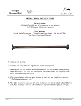
Figure 1-1 Outline drawings - Compact prover
Typical 8”, 12”, 18”, 24”, 34” and 40” NEC Type
Typical 8”, 12”, 18”, 24”, 34” and 40” ATEX Type

Operating and maintenance instructions Section 1: Introduction
3-9008-701 Rev J January 2015
Mechanical description 5
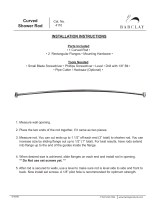
Figure 1-1 Outline drawings - Compact prover (Continued)
Typical 12” Mini NEC Type
Typical 12” Mini ATEX Type

6 Technical data
Section 1: Introduction Operating and maintenance instructions
January 2015 3-9008-701 Rev J
1.4 Technical data
Materials of construction:
Standard: 17-4 stainless steel flow tube with hard chrome plating, carbon steel pipe and flanges
Standard maximum working pressure:
8" to 24" Size: 150 lb. ANSI 285 psig (1965 kPa) @ 100.F (38.C)
260 psig (1793 kPa) @ 200.F (93.C)
8" to 24" Size: 300 lb. ANSI 740 psig (5102 kPa) @ 100.F (38.C)
675 psig (4654 kPa) @ 200.F (93.C)
8" to 24" Size: 600 lb. ANSI 480 psig (10204 kPa) @ 100.F (38.C)
1350 psig (9308 kPa) @ 200.F (93.C)
34" and 40" Size: 300 lb. ANSI 740 psig (5102 kPa) @ 100.F (38.C)
675 psig (4654 kPa) @ 120.F (49.C)
For intermediate pressures refer to ANSI B16.5
Prover size based on flow tube diameter.
Maximum working temperature:
8” to 24" Size: -20 to 200.F (-29 to 93.C)
Follow all the safety and equipment limits recommended in 1.4 Technical data of this manual. It
is the owner’s and/or purchaser’s responsibility to comply with these parameters.
PERSONAL PROTECTION HAZARD
Follow all parameters for the compact prover indicated below.
Failure to do so may result in injury or equipment damage.
Page is loading ...
Page is loading ...
Page is loading ...
Page is loading ...
Page is loading ...
Page is loading ...
Page is loading ...
Page is loading ...
Page is loading ...
Page is loading ...
Page is loading ...
Page is loading ...
Page is loading ...
Page is loading ...
Page is loading ...
Page is loading ...
Page is loading ...
Page is loading ...
Page is loading ...
Page is loading ...
Page is loading ...
Page is loading ...
Page is loading ...
Page is loading ...
Page is loading ...
Page is loading ...
Page is loading ...
Page is loading ...
Page is loading ...
Page is loading ...
Page is loading ...
Page is loading ...
Page is loading ...
Page is loading ...
Page is loading ...
Page is loading ...
Page is loading ...
Page is loading ...
Page is loading ...
Page is loading ...
Page is loading ...
Page is loading ...
Page is loading ...
Page is loading ...
Page is loading ...
Page is loading ...
Page is loading ...
Page is loading ...
Page is loading ...
Page is loading ...
Page is loading ...
Page is loading ...
Page is loading ...
Page is loading ...
Page is loading ...
Page is loading ...
Page is loading ...
Page is loading ...
Page is loading ...
Page is loading ...
Page is loading ...
Page is loading ...
Page is loading ...
Page is loading ...
Page is loading ...
Page is loading ...
Page is loading ...
Page is loading ...
Page is loading ...
Page is loading ...
Page is loading ...
Page is loading ...
Page is loading ...
Page is loading ...
Page is loading ...
Page is loading ...
Page is loading ...
Page is loading ...
Page is loading ...
Page is loading ...
Page is loading ...
Page is loading ...
Page is loading ...
Page is loading ...
Page is loading ...
Page is loading ...
Page is loading ...
Page is loading ...
Page is loading ...
Page is loading ...
Page is loading ...
Page is loading ...
Page is loading ...
Page is loading ...
Page is loading ...
Page is loading ...
/