Page is loading ...

The warranties made by MSA with respect to the product are voided if the product is not installed, used, and serviced in
accordance with the instructions in this manual. Please protect yourself and your employees by following the instructions.
Please read and observe the WARNINGS and CAUTIONS inside. For any additional information relative to use or repair, write
or call 1-877-672-3473 during regular working hours.
These devices comply with Part 15 of the FCC Rules. Operation is subject to the following two conditions; (1) this device may not
cause harmful interference and (2) these devices must accept any interference received, including interference that may cause
undesired operation. Changes or modifications not expressly approved by the manufacturer could void the user’s authority to
operate the equipment.
NOTE: This equipment has been tested and found to comply with the limits for a Class A digital device, pursuant to Part 15 of
the FCC Rules. These limits are designed to provide reasonable protection against harmful interference when the equipment is
operated in a commercial environment. This equipment generates, uses, and can radiate radio frequency energy and, if not
installed and used in accordance with the instruction manual, might cause harmful interference to radio communications.
Operation of this equipment in a residential area is likely to cause harmful interference in which case the user will be required to
correct the interference at his or her expense.
MSA 412 (L) Rev.5 © MSA 2014 Prnt. Spec. 10000005389(A) Mat. 10068929
Doc. 10068929
THIS MANUAL MUST BE CAREFULLY READ AND FOLLOWED BY ALL PERSONS WHO HAVE, OR WILL HAVE, THE RESPONSI-
BILITY FOR INSTALLING OR USING THIS EQUIPMENT. THIS EQUIPMENT WILL PERFORM AS DESIGNED ONLY IF USED AND
MAINTAINED ACCORDING TO THE INSTRUCTIONS; OTHERWISE IT COULD FAIL TO PERFORM AS DESIGNED, AND PERSONS
WHO RELY ON THE EQUIPMENT COULD SUSTAIN SERIOUS PERSONAL INJURY OR DEATH.
MSA Accountability
System
CARE AND USE
"
WARNING

DESCRIPTION AND REQUIREMENTS
2
MSA 412 (L) Rev. 5 - 10068929
DESCRIPTION OF ACCOUNTABILITY SYSTEM AND BASE STATION INTERFACE
The MSA Accountability System provides the ability to monitor telemetry-equipped MSA PASS devices from a remote location.
The MSA Accountability System consists of the following components:
• An MSA air mask equipped with telemetry
• Personal computer (not provided by MSA)
• Base Station Kit, includes software, antenna kit, USB cable and power supply (P/N 10072240)
• FireHawk M7 Tag Writer Interface Box (P/N 10083876)
• FireHawk M7 ID Tags (P/N 10083875)
The accountability function in the MSA PASS device is automatically activated when an air mask is first pressurized.
After all of the initial information is obtained by the base station from the air mask, the accountability software will serve as a
communication link to the air mask.
ID Tags are used in conjunction with the Accountability System to assign names and teams to the air mask. By utilizing ID tags,
each air mask can be identified on the accountability software screen by name and team assignment.
PC SYSTEM REQUIREMENTS
Operating System: Windows XP Service Pack 3 or higher, Windows 7-32 and 64 bit or Windows 8-32 or 64 bit.
Minimum Hardware Requirements:
1 GHz Pentium III processor or equivalent / 256 MB RAM / USB 1.1 / 16 MB graphic card (resolution 1024x768 pixel or greater, 256
colors) / 200 MB free disk space
Optimum Hardware Requirements (Preferred):
1.8 GHz Pentium IV processor or greater / 512 MB RAM / 32 MB AGP graphic card (resolution 1024x768 pixel or greater, 16,7 Mio
colors, 2 RGB or DVI) / 1.5 GB free disk space.
Remote PC speakers may be required to ensure incident command is able to hear audible warnings from the PC.
Follow the PC or notebook computer manufacturer’s recommendations for exposure to environmental conditions to prevent
damage to the system. Failure to do so may cause system failure and the loss of monitoring capability on the PC.
"
WARNING
Table of Contents
Description and PC System Requirements . . . . . . . . . . . . . . . . .2
Software Installation-Windows . . . . . . . . . . . . . . . . . . . . . . . . . . . .3
Software Installation-Windows 64 bit . . . . . . . . . . . . . . . . . . . . .7
Base Station Hardware Installation . . . . . . . . . . . . . . . . . . . . . . . .8
Initial System Set-Up, Software . . . . . . . . . . . . . . . . . . . . . . . . . . . .9
Initial Set-Up, SCBA . . . . . . . . . . . . . . . . . . . . . . . . . . . . . . . . . . . . . .12
ID Tag Programming and PASS Device Tagging . . . . . . . . . . .14
Monitoring SCBA . . . . . . . . . . . . . . . . . . . . . . . . . . . . . . . . . . . . . . .17
Using Teams . . . . . . . . . . . . . . . . . . . . . . . . . . . . . . . . . . . . . . . . . . . . .19
SCBA Statistics Display . . . . . . . . . . . . . . . . . . . . . . . . . . . . . . . . . . .20
The Evacuation Command . . . . . . . . . . . . . . . . . . . . . . . . . . . . . . .21
PAR Timer . . . . . . . . . . . . . . . . . . . . . . . . . . . . . . . . . . . . . . . . . . . . . . .22
Loss of Radio Communication . . . . . . . . . . . . . . . . . . . . . . . . . . .23
Using Multiple Base Stations . . . . . . . . . . . . . . . . . . . . . . . . . . . . .24
Incident Report Generation . . . . . . . . . . . . . . . . . . . . . . . . . . . . . .25
Accountability of Firefighters without Telemetry . . . . . . . . . .27
Maintenance . . . . . . . . . . . . . . . . . . . . . . . . . . . . . . . . . . . . . . . . . . . .28
Appendix/Troubleshooting . . . . . . . . . . . . . . . . . . . . . . . . . . . . . .29
Warranty . . . . . . . . . . . . . . . . . . . . . . . . . . . . . . . . . . . . . . . . . . . . . . . .30

SOFTWARE INSTALLATION - WINDOWS
3
MSA 412 (L) Rev. 5 - 10068929
INSTALLING THE SOFTWARE
1. Ensure you have the latest version of the software by comparing it to the version available on MSA’s website,
http://us.msasafety.com/productSoftwareDownloads
2. Insert the CD or double click the file name to download it from the website.
a. The installer will begin to autorun.
3. Click NEXT on the InstallShield Wizard screen.
4. Read the license agreement, click ACCEPT, and click NEXT.

SOFTWARE INSTALLATION - WINDOWS
4
MSA 412 (L) Rev. 5 - 10068929
5. Populate the User Name and Company Name fields and determine who can run the application. Click NEXT.
6. Choose the type of installation and click NEXT.
7. Click on SINGLE WORKSTATION INSTALLATION and click NEXT.

SOFTWARE INSTALLATION - WINDOWS
5
MSA 412 (L) Rev. 5 - 10068929
8. Select the destination folder and click NEXT.
9. Click INSTALL to begin the installation process.

SOFTWARE INSTALLATION - WINDOWS
6
MSA 412 (L) Rev. 5 - 10068929
10. When installation is complete, click FINISH.

SOFTWARE INSTALLATION - WINDOWS 64 BIT
7
MSA 412 (L) Rev. 5 - 10068929
1. Go to the computer’s CONTROL PANEL, then CONTROL PANEL
2. Click on ADMINISTRATIVE TOOLS.
3. In Administrative Tools click on COMPUTER MANAGEMENT.
4. In Computer Management, under OTHER DEVICES, right click on TELEMETRY TRANSCEIVER BOX.
5. Click UPDATE DRIVER SOFTWARE.
6. In Driver Software, select BROWSE MY COMPUTER FOR DRIVER SOFTWARE.
7. Using the browse button, select the location - C:/ProgramFiles(x86)MSA/MSA Accountability System. Be sure to put a check
mark in the INCLUDE SUBFOLDERS BOX before continuing.
8. Click NEXT.
9. A screen will appear confirming successful update of the driver software. Close this screen. Installation is complete.

BASE STATION HARDWARE INSTALLATION
8
MSA 412 (L) Rev. 5 - 10068929
INSTALLING THE HARDWARE
• Installation of this device requires professional installation. Base station antenna attachment should only be performed after
proper instruction.
• The base station is not waterproof. DO NOT mount the base station to the exterior of a vehicle.
• When using a fixed base antenna, refer to installation instruction sheet (P/N 10098768).
1. Connect the power cord to the left side of the base station and plug it into a DC (12-24 V) vehicle power outlet. (An AC power
adapter (P/N 10047342) is also available. This adapter is designed to connect to a standard 120V outlet.)
Only use MSA power adapters (P/N 10049410 and P/N 10047342). Other power adapters may blow the fuse and are not
covered by warranty.
2. Connect the antenna to the base station by threading the TNC fitting onto the jack on the right side of the base station.
NOTE: The base of the antenna has a magnetic platform. It is recommended that it be placed in an area that is elevated above the
base station and is free from obstruction, such as the roof of a vehicle.
Use only antenna provided by MSA for use with this base station. Failure to do so will be in violation of the FCC approval of
this device. Antenna: P/N 10072527; Magnetic Base: P/N 10075756, and Fixed Base Antenna: P/N 10098766.
3. Connect the USB cable to the port on the left side of the base station and to an empty USB port on the PC.
Use only USB cables provided by MSA for use with this base station. Failure to do so will be in violation of the FCC approval of
this device.
4. The base station has two (2) holes in the housing that can be used to mount the base station to a wall or table top.
"
CAUTION
"
CAUTION
"
CAUTION
"
CAUTION

INITIAL SYSTEM SET-UP, SOFTWARE
9
MSA 412 (L) Rev. 5 - 10068929
INITIAL SYSTEM SET-UP
1. Double click on the MSA ACCOUNTABILITY SYSTEM SOFTWARE icon on the desktop. The program can also be found under
Start / Program Files / MSA / MSA Accountability System.
2. The software will open to the main screen of the Accountability System Software.
NOTE: User of the software must be at least a “main user” registered with the PC. “Guest” users will not be able to access the MSA
Accountability System Software. If the icon or the program cannot be located, contact the PC Administrator.
3. Click on SYSTEM, SETTING, SETTINGS SCBA MONITORING
4. The following default settings should be reviewed and adjusted based upon the fire department’s standard operating
procedures.
a. The “PAR timer” setting is the time interval in which the PAR (Personnel Accountability Report) reminder will be displayed
during an incident. The default is 15 minutes.
b. “Remaining time alarm” determines the set point for the estimated time remaining based on the cylinder pressure pop-up
window. The default is 10 minutes.
c. “Allow single evacuation” permits a single firefighter to be sent an evacuation command.
d. “Pressure alarm threshold” permits the user to set the Pressure Alarm to match the air mask being used - 33% for 2013
edition units, or 25% for 2007 edition and earlier units.

INITIAL SYSTEM SET-UP, SOFTWARE
10
MSA 412 (L) Rev. 5 - 10068929
5. Other default settings not typically changed are as follows:
a. “Team Strength” refers to the number of firefighters allowed in a single team. The default is 6 firefighters per team.
b. “Pressure Unit” refers to the unit by which cylinder pressure will be displayed. The default is PSI.
c. “Icon” allows the selection of the helmet icon that will appear to represent each firefighter being monitored. The default is a
“traditional” helmet.
d. “Color” refers to the cylinder pressure for each firefighter. By default, the following color scheme was chosen to remain
consistent with that of the heads-up display to build consistency within the fire scene.
• BLUE - New Person
• GREEN - Cylinder Pressure above 50%
• YELLOW - Cylinder Pressure between 33% and 50% (2013 edition) , or 25% and 50% (2007 edition and earlier)
• RED - Cylinder Pressure below 33% (2013 edition), or 25% (2007 edition and earlier)
6. Under the “Alarms” tab, the alarms that will be displayed during an SCBA monitoring session can be changed. The default
settings are shown below.
Ensure the computer interface being used with the Accountability System is equipped with speakers, and that the system
volume and speakers are set to a level adequate for the operator to hear the audible alerts during fire scene operations.
a. “Motion Alarm” will alert when the PASS alarm is activated by a firefighter due to lack of motion. The default sound will be
that of the air mask’s PASS alarm.
"
CAUTION

INITIAL SYSTEM SET-UP, SOFTWARE
11
MSA 412 (L) Rev. 5 - 10068929
b. “Temperature Alarm” refers to the thermal alarm activated by a firefighter’s thermal indicator on the air mask. A pop-up
warning window can be enabled or disabled by checking the box next to “Temperature Alert”. A thermometer icon will be
displayed in the SCBA statistics window in the event of a thermal alarm for any firefighter regardless of this box being
checked.
c. “Low Battery Alarm” will alert when a firefighter’s air mask has a low battery condition. A pop-up warning window can be
enabled or disabled by checking the box next to “Low Battery Alarm”. A battery icon will be displayed in the SCBA statistics
window in the event of a low battery alarm for any firefighter regardless of this box being checked.
d. “Pressure Alarm” will alert when a firefighter has reached approximately 33% (default 2013 edition) or 25% (2007 edition or
earlier) of full cylinder pressure. The default sound is that of the Audi-Larm Audible Alarm ringing.
e. “Manual Alarm” will alert when the PASS alarm has been activated manually by a firefighter. The default sound is that of the
air mask’s PASS alarm.
f. “Loss of Radio Link” will alert when a firefighter’s air mask has lost radio communication with the base station. This will occur
when the device is out of range or in an area of poor radio communication. A pop-up warning window can be enabled or
disabled by checking the box next to “Loss of Radio Link Alarm”. A red X over an antenna icon will be displayed in the SCBA
statistics window and next to the firefighter’s helmet icon if the air mask loses communication with the base station
regardless of this box being checked.
g. “Supply Voltage Alarm” will alert when the power supply to the base station has been disconnected during a monitoring
session.
h. “PAR Alert” will alert when the specified PAR time has been reached during a monitoring session.
i. “Remaining Time Alarm” will alert when a firefighter’s air mask has calculated the remaining time specified in the white
textbox of this window. A pop-up warning window can be enabled or disabled by checking the box next to “Remaining
time alert”. The time calculated by the air mask is always displayed in the SCBA statistics window regardless of the box being
checked.
By default, the air mask calculates the remaining time based on the time to reach 0 psi. In the air mask interface module (or
link) software, the air mask can be configured to calculate remaining time based on the time to reach the low pressure alarm
point. Before monitoring SCBA using this software, be sure of the time remaining calculation that the air mask is using.
NOTE: The sounds associated with each of these alarms can be changed under this menu. To assign a new sound to any of the
alarms shown, select the appropriate .wav file. The .wav file must be renamed to match the alarm file name specified as the default
shown above. For example, to replace the alarm sound for the motion alarm, rename the desired .wav file so that it matches the
default name shown for that alarm.
NOTE: If the save icon is not clicked before closing the settings window, the changes will not take effect.
7. An information warning will prompt the user to accept the changes and save the settings. If 25% is selected as the pressure
alarm threshold, the user will be prompted with the information warning as shown. For NFPA product approved prior to 2007,
the user should select the “Accept” button in order to set the accountability end of service life indicator warnings to 25%, con-
sistent with pre-2013 NFPA compliant SCBA.
8. Close the settings window. The program will then return to the main screen.
"
CAUTION

INITIAL SYSTEM SET-UP, SCBA
12
MSA 412 (L) Rev. 5 - 10068929
SCBA SET-UP
Prior to setting up the SCBA, determine the duration of ID Tag Memory. Productions units are set to delete the tag memory after
off for 24 hours.
NOTE: ID Tag memory can be kept current until the next ID tag is read. Use the interface software with the interface box and use
the reader / ID tag writer to change the settings within the PASS device.
ID Tag Information
The name ID is used to assign a firefighter name to an air mask. The name ID tag must be scanned into the air mask at the start of
each shift (every 24 hours by default). The ICM Link program can be used to change this default to allow a name ID to be perma-
nently assigned to the air mask until a new name ID tag is scanned. If a team ID tag was scanned into the air mask, but a name ID
tag was not scanned, the team ID will be displayed on the SCBA monitoring software to provide accountability even if the fire-
fighter forgot to scan the name ID tag. If a team ID was not assigned to the air mask, the air mask’s PASS device serial number will
be displayed on the firefighter’s ID when logged onto the base station.
The team ID is used to assign a permanent team name and seat position to an air mask. When a team name is assigned to an air
mask, it will automatically create this team on the PC software and move that firefighter into the specified team and team
position. Once a team ID tag is scanned into an air mask, this team ID will remain with the air mask until another team ID tag is
scanned.
The special ID is used to assign a specific base station ID to an air mask. When more than one (1) base station is present and
actively monitoring at an incident, an air mask with an assigned base station will search for the preferred base station first to log
onto, and if it does not find the assigned base station within 20 seconds, it will search for the first available base station and log on
to it. Once a base station ID tag is scanned into an air mask, this base station ID will remain with the air mask until another base
station ID tag is scanned (a base station of 00000000, eight *8) zeroes can be scanned into the ICM to remove the base station
preference).
Decision 1 - Identifying base station assignment
Option A - The PASS device can be programmed to look for a particular base station ID. This is useful for
departments with multiple base stations or neighboring departments with base stations.
Option B - Do nothing and the SCBA will select whatever base station is available.
NOTE: A firefighter’s SCBA will look for the assigned base station. If it cannot be found, the SCBA will assign itself to an active base
station in the area. Once connected to a base station the PASS device will not look for the originally assigned base station until the
unit is shut down and re-started.
Decision 2
Option A - Create a tag identifying a team or truck assignment. This functionality allows for individuals to
automatically be assigned to a team or truck once the SCBA is pressurized. The team or truck
assignment is permanent until another team or truck tag is scanned into the PASS device.
Option B - Do nothing, allow incident command to take individuals from the holding bin into teams or trucks
during an event.
NOTE: Creating team or truck assignments still allows incident command to move firefighters from one truck or team assignment
to another.
On the ICM TxR team assignments are permanent and can only be replaced by a team with a different name.
Decision 3
To set up the SCBA, determine how to uniquely identify each person on the accountability screen.
There are three options:
Option A - Individual Name
Each firefighter is assigned an ID Tag with his/her name on it (18 characters maximum) on it.
The name is displayed on the screen. Each firefighter tags in each day as previously described. A fire-
fighter must tag in every 24 hours or when he/she switches to a new air mask, whichever comes first.
"
CAUTION

INITIAL SYSTEM SET-UP, SCBA
13
MSA 412 (L) Rev. 5 - 10068929
Option B - SCBA Name
Generic name for SCBA, use one tag to change the SCBA to be a seat identifier or a general SCBA
number. To use the generic tags, the PASS devices must be set to “keep current ID in memory until ID
Tag is read.”
Option C - To identify each by serial number, do nothing at all.
Based on the selections above, refer to the following tag set-up instructions.

ID TAG PROGRAMMING AND PASS DEVICE TAGGING
14
MSA 412 (L) Rev. 5 - 10068929
ID Tag Programming and PASS Device Tagging
The SCBA monitoring window must be closed before the tag writer portion of the software can be used. Failure to close this
window may cause the ID Tag Writer to not respond and may prevent the use of the Tag Writer feature until the SCBA
monitoring window is closed.
The ICM Tx / TxR Unit Data Program software or the FireHawk M7 Interface Module Software must not be running while the
base station software is running on the same PC. If both programs are open, the PC may not properly communicate with the
base station or interface module.
Set-Up for Programming ID Tags
1. Connect the interface module to an open USB port on the PC.
2. Click MISSION, SCBA MONITORING, TAG WRITER in the main screen of the base station software to launch the Tag Writer
Interface Window. The following window will appear:
NOTE: For additional information to the FireHawk M7 Interface Module Software Instructions, P/N 10088977 and ICM Tx Unit Data
Program Software Instructions, P/N 10067066.
Programming and tagging base station ID Tags
1. Click the circle next to SPECIAL TAG.
2. Click the circle next to BASE STATION.
3. Locate the serial number for the base station to be associated with this ID Tag.
NOTE: The serial number is the 8 digit number located on the bottom of the base station. The base station serial number is also
displayed at the top of the SCBA monitoring window of the MSA Accountability System Software.
4. Type the base station serial number in the white text entry box.
5. Hold the ID Tag parallel to the interface module for FireHawk M7 Reader/Writer or insert an ID Tag into the open slot on the
front of the ICM Tag Writer.
"
CAUTION
"
CAUTION

ID TAG PROGRAMMING AND PASS DEVICE TAGGING
15
MSA 412 (L) Rev. 5 - 10068929
6. Click WRITE.
7. A small dialog box will appear to confirm that the data was programmed successfully.
8. Verify the information in the box is the information intended (base station ID number on the bottom of base station).
9. Refer to Scanning the ID Tag into the FireHawk M7XT/M7 Control Module with Telemetry section below.
NOTE: The base station ID will remain in the air mask until a new base station ID is entered.
NOTE: To remove a base station preference from an air mask, a base station ID Tag containing “00000000” (8 zeroes) must be
created and scanned into the air mask.
Programming and Tagging ID Tags Team/Truck Assignments
1. Click the circle next to “Team”.
2. Enter the Teams/Position ID in the white text field. The Team ID can be a maximum of 10 characters if a seat position is not
specified. For example, to enter a team ID of “Truck 1, Position 2”, type “Truck 1/2”. This will display as Truck 1/2” as the
firefighters team ID during SCBA monitoring. Since only 8 characters will be displayed during SCBA monitoring, an entry of
“Truck_1_/2” (where _ represents a space) will display as “Truck 1” and the position number will be hidden.
NOTE: A position is defined as the location within the team/truck assignment screen of the accountability system. If the position is
not selected within the tag when it’s written then the team members still populate a team/truck assignment, but will not be in any
particular order. To assign a position in addition to the team ID, type the team ID first, then type “/” and type a position number (1
through 6). The team ID can be a maximum of 8 characters if a seat position is specified as the “/#” takes up the additional two
characters.
3. Hold the ID tag parallel to the interface module or insert and ID tag into the open slot on the front of the ICM Tag Writer if the
air mask uses an ICM TxR.
4. Click WRITE.
5. A small dialog box will appear to confirm that the data was programmed successfully.
6. Verify the information in the box is the information intended Team / Position ID.
7. Refer to Scanning the ID Tag into the FireHawk M7XT/M7 Control Module with Telemetry section below.
NOTE: The Team/Position ID will remain in the air mask until a new Team/Position ID is entered.
Programming Name ID Tags
1. Click the circle next to NAME.
2. Enter the name or ID in the white text field. The name ID can be up to 18 characters in length.
3. Hold the ID tag parallel to the interface module or insert an ID Tag into the open slot on the front of the ICM Tag Writer if the
air mask uses an ICM TxR.
4. Click WRITE.
5. A small dialog box will appear to confirm that the data was programmed successfully.
6. Verify the information in the box is the information intended (name).
7. Refer to Scanning the ID Tag into the FireHawk M7XT/M7 Control Module with Telemetry section below.
NOTE: By default, the name ID will remain in the air mask for 24 hours before expiring. This setting can be changed to allow the
name ID to remain until a new name ID is entered. To change this setting, the FireHawk M7 Interface Module software or ICM Tx
Unit Data Program software must be used. Refer to the appropriate manual for additional instructions.
NOTE: Verify the tagging process by checking each SCBA by following the Monitoring SCBA section of this manual.
SCANNING THE ID TAG INTO THE FIREHAWK M7XT/M7 CONTROL MODULE WITH TELEMETRY
1. Prior to pressurization of the air mask and during inspection, the user can “tag in” to the air mask. The
most recent ID Tag data that is stored in the FireHawk M7XT/M7 Control Module will be used as the iden-
tification for the air mask on the MSA Accountability System Software. If no ID Tag data is assigned to the
air mask, the FireHawk M7XT/M7 Control Module serial number will be used as its identification on the
base station PC screen.
NOTE: The air mask must not be pressurized and FireHawk M7XT/M7 Control Module must have batteries installed (at the Power
Module), but be turned off to scan the ID Tag.

ID TAG PROGRAMMING AND PASS DEVICE TAGGING
16
MSA 412 (L) Rev. 5 - 10068929
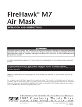
2. Take the ID Tag and place the attachment clip between your fingers on your left hand. The ID Tag should lay in your palm.
3. Move the FireHawk M7XT/M7 Control Module over top of the ID Tag.
4. Press and hold the green mode button with your thumb for 2 seconds. The word TAG will display.
DO NOT use the tag to press mode button.
5. At that point, the word will change to “OK” within a few seconds confirming the tagging process is
complete.
DO NOT use the tag to press the mode button; place it on top of the FireHawk M7XT/M7 Control Module or next to the
FireHawk M7XT/M7 Control Module. The tagging instructions must be followed to have the ID Tag within range of the short
range radio to complete the tagging process. If the tag is not, the PASS device can lock-up showing the word “TAG” or
“DATA” and cannot be shut-off. To fix the lock-up, the batteries must be removed for 10 seconds and then re-installed.
6. The word TAG will display for 10 seconds if the mode button is not pressed again. If the mode button is pressed again after the
word TAG appears, then the PASS will enter data mode showing the word DATA. To get back into tag mode, press the mode
button again to enter sleep mode and repeat the previous steps.
NOTE: The “data” mode is used to change the device settings or read the data log while using the FireHawk M7 Interface software.
"
WARNING
Incorrect Method Incorrect Method Incorrect Method

MONITORING SCBA
17
MSA 412 (L) Rev. 5 - 10068929
Monitoring SCBA
1. Double click on the MSA Accountability System Software icon.
2. To being monitoring SCBAs using the base station software, click MISSION, SCBA MONITORING, SCBA MONITORING in the main
screen of the base station software.
3. The SCBA monitoring window will appear.
4. Check the status of the base station.
a. The LED labeled “PC Link” will alternate from RED to GREEN for approximately 20 seconds. When the “PC Link” LED stops
flashing and remains GREEN, the base station is ready to begin logging firefighters onto the system.
b. The LED labeled “Power” should be GREEN. If the “PC Link” light is not GREEN, verify the base station is connected properly.
5. As firefighters pressurize their air masks and the PASS devices are turned on, helmet icons (blue, by default) will appear in the
“holding bin” frame of the SCBA monitoring window.
NOTE: The “holding bin” is the white area in the upper left portion of the window.
NOTE: When the icon first appears, it displays “Activated” under the helmet icon. When the firefighter is fully logged onto the sys-
tem, the helmet icon will change to the color corresponding to the current cylinder pressure. By default, the colors indicating
cylinder pressure will correspond with the colors displayed in the heads-up display system receiver.
6. The full log-on process for a unit is less than 1 minute.
a. During the log-on process, the PC acquires data such as name ID, team assignment, pressure type, and current pressure
from the air mask.
b. During the log-on process the helmet icon may jump from the holding bin into a team automatically if a team ID was
assigned to the air mask using an ID Tag.
c. Refer to the Programming and Tagging ID Tags Team/Truck Assignments instructions in the ID Tag Programming and PASS
Device Tagging section of this manual for additional information on team assignments.
7. When the helmet icon changes from blue to a color corresponding to the cylinder pressure (RED, YELLOW, GREEN by default)
the air mask is fully logged onto the base station. The pressure reading is the last piece of information the base station reads
from the air mask before the log-on process is complete.
8. To confirm that a particular unit has completely logged onto the base station, verify the radio link status icon in the lower right
corner of the SCBA statistics frame is present. On the FireHawk M7XT/M7 Control Module, the radio link icon will be present in
the upper left corner of the LCD. On the ICM TxR Unit, an antenna icon is located in the upper right corner of the LCD display.

MONITORING SCBA
18
MSA 412 (L) Rev. 5 - 10068929
NOTE: If the air mask is turned off before the full log-in process is complete, the corresponding helmet icon will remain in the
holding bin until the SCBA monitoring window is closed.
For example, if an air mask’s log-on process is interrupted by turning the device off, a “ghost” icon will remain in the holding
bin even though the air mask is turned off. If that air mask is then turned on again, a new helmet icon will appear and the unit
will begin the log-on process again. In this case, even if the air mask completes the log-in process, a “ghost” helmet icon for
that unit may remain in the holding bin on the SCBA monitoring window. “Ghost” icons can be removed by clicking the icon
(or double left clicking) and selecting “remove person”.
NOTE: Once an air mask is fully logged onto a base station, that air mask cannot be monitored by another base station until the air
mask is turned off and completely logged off the current base station.

USING TEAMS
19
MSA 412 (L) Rev. 5 - 10068929
USING TEAMS
Using Team/Truck ID Tags
Team ID Tags can be used to assign a permanent team/truck assignment to a particular air mask. By scanning a Team ID Tag into a
FireHawk M7XT/M7 Control Module or ICM TxR Unit, teams are created automatically when a firefighter pressurizes an air mask. In
this case, when a firefighter pressurizes an air mask, the helmet icon associated with that firefighter will automatically move from
the holding bin to the appropriate team and position assignment. For more information on programming and using Team ID Tags,
refer to the ID Tag Programming and PASS Device Tagging section of this manual.
When using the Name Only ID Tags, as firefighters appear in the “holding bin” as their air masks are turned on, they can be
monitored most effectively by creating teams and dragging icons into the teams. Firefighters can be monitored individually by
clicking on the icon while they are in the holding bin. The information for each highlighted firefighter will be displayed in the
lower left frame of the screen.
Creating Teams/Truck
Click the NEW TEAM button at the top of the screen.
A team window will appear in the column to the right.
As many teams as needed can be created.
Teams will be named in succession i.e. Team 1, Team 2, Team 3, etc.
Team order can be arranged by RIGHT clicking and dragging the team to the desired location.
Adding a Firefighter to a Team/Truck
Drag the icon from the holding bin to the appropriate team.
NOTE: To drag multiple firefighters into a team at one time, click and hold the left mouse button and draw a box around the fire-
fighters to be moved. Release the left mouse button. Select any of the highlighted firefighters with the left mouse button and drag
them into the appropriate team.
Monitoring a Team/Truck
1. Click on the team of interest on the right side of the screen.
• All team member statistics appear in the lower left portion of the screen.
• To scroll between teams, the “page up” and “page down” keys can be used in addition to clicking the mouse.
Changing the Team Name/Truck
1. Click in the white text box in the upper left corner of the team window.
2. Type a new name and press enter.
NOTE: To retrieve previously entered team names from past sessions, click the drop down menu arrow at the far right side of the
text box. All past team names are displayed for selection.
Adding “Comments” to a Team/Truck
1. Click in the text box under the team name text box.
2. Type any additional team comments and press enter.
NOTE: To retrieve previously entered comments from past sessions, click the drop down menu arrow at the far right side of this
text box. All past team comments are displayed for selection.

SCBA STATISTICS DISPLAY
20
MSA 412 (L) Rev. 5 - 10068929
NOTE: SCBA statistics for each firefighter being monitored appear in the lower left portion of the SCBA monitoring window.
1. Pressure
• Displayed graphically for each unit via the cylinder icon in each box
• The actual pressure reading is displayed as transmitted from the air mask
2. Time Remaining
• The estimated time remaining value is displayed as calculated by the air mask
3. Radio Link Status
• The antenna icon at the lower right corner of the SCBA statistics window indicates that the base station/air mask
connection is established.
• If the air mask is out of range, the antenna icon will turn gray and a red X will appear until the air mask returns within range
of the base station.
• When an air mask loses communication with the base station longer than 1 minute, a timer with RED text will appear
below the time remaining calculation counter. This timer will keep track of the amount of time, in minutes, that a firefighter
is out of range and will disappear when the radio link is re-established.
4. Evacuation Status
• The RED and YELLOW arrows and GREEN check mark display the status of an evacuation signal.
• When an evacuation signal is sent by the base station, the “evacuate” or “running man” icon will turn RED and a black dot
will appear next to the RED arrow.
• When the air mask has received the signal, the running man icon will turn YELLOW and a black dot will appear next to the
YELLOW arrow.
• When the firefighter manually confirms the evacuation command, the running man icon will turn GREEN and a black dot
will appear next to the GREEN check mark.
5. Alarms
• If an air mask goes into a motion alarm, manual alarm, temperature alarm, pressure alarm, or low battery alarm, a window
will pop-up displaying the warning.
• These alarms will also appear in the SCBA statistics window.
- Thermometer icon - indicates thermal alarm
- Battery icon - indicates low battery warning
- Horizontal man down icon - indicates a PASS alarm
/