Page is loading ...

FireHawk™ M7
Air Mask
NFPA 1981: 2007 Edition
NFPA 1982: 2007 Edition
CBRN Agent Approved Air Mask
OPERATION AND INSTRUCTIONS
This device complies with Part 15 of the FCC Rules. Operation is subject to the following conditions:
(1) This device may not cause harmful interference and (2) this device must accept any interference that may cause
undesired operation.
TAL 708 (L) Rev. 1 © MSA 2007 Prnt. Spec. 10000005389(A) Mat. 10082858
Doc. 10082858
This manual must be carefully read and followed by all persons who have or will have the responsibility for using
or servicing this air mask. This air mask will perform as designed only if used and serviced according to the instruc-
tions; otherwise it could fail to perform as designed, and persons who rely on the air mask could sustain serious
personal injury or death.
This Self-Contained Breathing Apparatus (SCBA) is certified by the National Institute of Occupational Safety and Health
(NIOSH).
Changes and modifications not expressly approved by the manufacturer could void the user’s authority to operate the
equipment.
Use in conjunction with personal protective ensembles that provide appropriate levels of protection against der-
mal hazards.
Some CBRN agents may not present immediate effects from exposure, but can result in delayed impairment, ill-
ness, or death.
Direct contact with CBRN agents requires proper handling of the SCBA after each use and between multiple entries
during the same use. Decontamination and disposal procedures must be followed. If contaminated with liquid
chemical warfare agents, dispose of the SCBA after decontamination.
The respirator should not be used beyond 6 hours after initial exposure to chemical warfare agents to avoid possi-
bility of agent permeation.
FAILURE TO FOLLOW THE ABOVE ITEMS IN ADDITION TO ALL ESTABLISHED CBRN PROTECTIVE MEASURES CAN
RESULT IN SERIOUS PERSONAL INJURY OR DEATH.
DANGER
The warranties made by MSA with respect to the product are voided if the product is not installed, used and serviced in
accordance with the instructions in this manual. Please protect yourself and your employees by following the instructions.
Please read and observe the WARNINGS and CAUTIONS inside. For any additional information relative to use or repair,
write or call 1-800-MSA-2222 during regular working hours.

INTRODUCTION
NIOSH APPROVAL INFORMATION
CAUTIONS AND LIMITATIONS
I- Contains electrical parts which have not been evaluat-
ed as an ignition source in flammable or explosive
atmospheres by MSHA/NIOSH.
J- Failure to properly use and maintain this product could
result in injury or death.
M- All approved respirators shall be selected, fitted, used
and maintained in accordance with MSHA, OSHA and
other applicable regulations.
N- Never substitute, modify, add or omit parts. Use only
exact replacement parts in the configuration as speci-
fied by the manufacturer.
O- Refer to Users Instructions, and/or maintenance man-
uals for information on use and maintenance of these
respirators.
S- Special or critical User’s Instructions and/or specific
use limitations apply. Refer to user instructions before
donning.
CAUTIONS AND LIMITATIONS OF USE FOR CBRN
SCBA
Q- Use in conjunction with personal protective ensembles
that provide levels of protection against dermal haz-
ards.
R- Some CBRN agents may not present immediate
effects from exposure, but can result in delayed
impairment, illness, or death.
T- Direct contact with CBRN agents requires proper han-
dling of the SCBA after each use and between multi-
ple entries during the same use. Decontamination
and disposal procedures must be followed. If conta-
minated with liquid chemical warfare agents, dispose
of the SCBA after decontamination.
U- The respirator should not be used beyond 6 hours
after initial exposure to chemical warfare agents to
avoid possibility of agent permeation.
S - SPECIAL OR CRITICAL USER’S INSTRUCTIONS
Approved for use at temperatures above -25°F. Approved
only when the compressed-air container is fully charged
with air meeting the requirements of the Compressed Gas
Association Specification G-7 for quality verification level
(grade) D air or equivalent specifications. In fire service
applications, MSA recommends breathing air quality in
accordance with NFPA 1989. The cylinder shall meet
applicable DOT specifications.
Do not alter this air mask. Altering will void the Intrinsic-
Safety rating and may affect the Intrinsic-Safety of the
device. Misuse or abuse of the heads-up display system
(FireHawk M7 HUD), FireHawk M7 Control Module, or
FireHawk M7 Power Module or using this equipment in a
manner or situation not intended by the manufacturer, may
result in damage to the FireHawk M7 HUD, FireHawk M7
Control Module, or FireHawk M7 Power Module, may
result in personal injury or death to user or persons depen-
dent on the user. Always inspect the FireHawk M7 HUD for
damage before use. If damage is found, immediately
remove the device from service. The FireHawk M7 HUD,
FireHawk M7 Control Module, and FireHawk M7 Power
Module are approved intrinsically-safe and conform to
UL/ANSI 913 for use in Class I, Div. I, Groups C and D
hazardous locations, temperature rating T3.
Use the air mask with adequate skin protection when
worn in gases and vapors that poison by skin absorption
(for example: hydrocyanic-acid gas). In making renewals
or repairs, parts identical with those furnished by the
manufacturer under the pertinent approval shall be main-
tained.
Approval for use against CBRN chemical warfare agents
is maintained only when using approved components and
following instructions listed on the NIOSH approval matrix
(P/N 10083874)
Do not mark the air mask, i.e., with stamps, labels, paint,
or other method. Use of such markings may interfere with
apparatus use or may constitute a flammability hazard.
2
TAL 708 (L) Rev. 1 - 10082858
TABLE OF CONTENTS
NIOSHApprovalInformation .........................................................................2
SpecialorCriticalUsersInstructions ...................................................................2
Description .......................................................................................5
InspectionandFunctionalTests .......................................................................9
Donning.........................................................................................13
UsingtheAirMask ................................................................................17
ColdWeatherOperation ............................................................................25
URCAssemblyOperation...........................................................................27
RemovingtheApparatus ...........................................................................29
CleaningandDisinfecting ...........................................................................33
FlowTestandOverhaulRequirements.................................................................35
Quick-FillSystemOperation.........................................................................37
ExtendAireSystem ................................................................................41
Appendix........................................................................................43

INTRODUCTION
For more information on the air mask use and perfor-
mance standards, please consult the following publica-
tions:
NFPA Standard 1500, Fire Department Occupational
Safety and Health Programs (Chapter 5) and NFPA 1981
Standard, on Open-Circuit SCBA’s for Fire Service. Above
publications are available from the following: National Fire
Protection Association, Batterymarch Park, Quincy, MA
22269.
ANSI Standard Z88.5, Practices for Respiratory Protection
for the Fire Service; and, ANSI Standard Z88.2, Practices
for Respiratory Protection. American National Standards
Institute, 1430 Broadway, New York, NY 10018.
OSHA Safety and Health Standards (29 CFR 1910) (see
specifically Part 1910. 134), available from the
Superintendent of Documents, U. S. Government Printing
Office, Washington, DC 20402. Compressed Gas
Association, Inc., 1725 Jefferson Davis Hwy., Suite 1004,
Arlington, VA 22202.
Note: The FireHawk M7 HUD, FireHawk M7 Control
Module, and FireHawk M7 Power Module have been test-
ed and found to comply with the limits for a Class B digi-
tal device, pursuant to Part 15 of the FCC Rules. These
limits are designed to provide reasonable protection
against harmful interference in a residential installation.
This equipment generates, uses, and can radiate radio
frequency and, if not installed in accordance with instruc-
tions, may cause harmful interference to radio communi-
cations. However, there is no guarantee that interference
will not occur in a particular installation. If this equipment
does cause interference to radio or television reception,
which can be determined by turning the equipment off
and on, the user is encouraged to try to correct the inter-
ference by one or more of the following measures:
• Reorient or relocate the receiving antenna
• Increase the separation between the equipment and
the receiver
• Connect the equipment into an outlet on a circuit dif-
ferent from that to which the receiver is connected.
• Consult the dealer or an experienced radio/TV techni-
cian for help.
The FireHawk M7 HUD, FireHawk M7 Control Module,
and FireHawk M7 Power Module contain electrical
parts which have not been evaluated as an ignition
source in flammable or explosive atmospheres by
MSHA/NIOSH.
1. Read and follow all NIOSH and other approval limi-
tations.
2. DO NOT use the carrier and harness assembly as a
vertical raising or lowering device.
3. DO NOT use the air mask as an underwater device.
4. This system must be supplied with respirable
[Quality Verification Level (Grade) D, see ANSI/CGA
G-7.1-1989] or higher quality air; and a dew point
not to exceed -65°F (24ppm v/v) [Compressed Gas
Association Specification G-7.1 for Quality
Verification Level (Grade) D Gaseous Air]. In fire
service applications, MSA recommends breathing
air quality in accordance with NFPA 1989.
5. This device may not seal properly with your face if
you have a beard, gross sideburns or similar physi-
cal characteristics (see NFPA-1500 and ANSI
Z88.2). An improper facial seal may allow contami-
nants to leak into the facepiece, reducing or elimi-
nating respiratory protection. Do not use this
device if such conditions exist. The face-to-face-
piece seal must be tested before each use. Never
remove the facepiece except in a safe, non-haz-
ardous, non-toxic atmosphere.
6. Return to a safe atmosphere immediately if discol-
oration, crazing, blistering, cracking, or other dete-
rioration of the facepiece lens material is
observed.
7. Users must wear suitable protective clothing and
precautions must be taken so that the air mask is
not exposed to atmospheres that may be harmful
to it.
8. Take into account the following factors which may
affect the duration or the service life.
a. the degree of physical activity of the user;
b. the physical condition of the user;
c. the degree that the user’s breathing rate is
increased by excitement, fear, or other emotional
factors;
d. the degree of training or experience which the
user has had with this or similar equipment;
e. whether or not the cylinder is fully charged;
f. the presence in the compressed air of carbon
dioxide concentrations greater than the .04%
level normally found in atmospheric air;
g. the atmospheric pressure; if used in a pressur-
ized tunnel or caisson at 2 atmospheres (15 psi
gauge) the duration will be one-half as long as
when used at 1 atmosphere; at 3 atmospheres
the duration will be one-third as long; the service
life of the air mask is based on 1 atmosphere of
pressure.
h. the condition of the air mask.
Failure to follow this warning can result in serious per-
sonal injury or death.
3TAL 708 (L) Rev. 1 - 10082858

INTRODUCTION
CBRN AGENT APPROVAL LABEL
The MSA CBRN Agent approved air mask has this
approval label attached to the carrier and harness.
IMPORTANT NOTICE FOR RESPIRATOR USERS AND
RESPIRATORY PROTECTION PROGRAM
ADMINISTRATORS
1. An adequate respiratory protection program must
include knowledge of hazards, hazard assessment,
selection of proper respiratory protective equipment,
instruction and training in the use of equipment,
inspection and maintenance of equipment, and med-
ical surveillance. [See OSHA regulations, Title 29 CFR,
Part 1910.134 (c).]
2. This SCBA may be used only after proper instruction
and training in its use as specified in NFPA-1500 and
OSHA regulations Title 29 CFR, Part 1910.134.
3. Quantitative fit testing should be conducted to deter-
mine proper facepiece size prior to using the respira-
tor. A Fit Test Kit (MSA P/N 10044576) is available for
conducting quantitative fit tests with the Ultra Elite
Firehawk Facepieces. The facepiece donning instruc-
tions must be carefully followed when using the respi-
rator and when conducting fit tests.
5. The CBRN Firehawk Second Stage Regulator must be
flow tested every year and overhauled on a periodic
basis. An overhaul kit (MSA P/N 10048942) is avail-
able.
CONTACT INFORMATION
In the event of a product concern, contact your local MSA
authorized repair center or distributor, who will provide the
necessary information to MSA for issue resolution. To
report any serious concerns, or to speak with a certifica-
tion organization, ,use the following contact information:
Manufacturer
MSA Customer Service
Phone: 1-800-MSA-2222
Certifying Agencies
National Institue of Occupational Safety and Health
(NIOSH)
Phone: 412-386-6686
Safety Equipment Institute (SEI)
Phone: 703-442-5732
4
TAL 708 (L) Rev. 1 - 10082858

DESCRIPTION
DESCRIPTION
FireHawk M7 Air Masks from MSA are pressure-demand,
self-contained breathing apparatus (SCBA) certified by the
National Institute for Occupational Safety and Health
(NIOSH) for use in atmospheres immediately dangerous to
life or health:
``Immediately dangerous to life or health’’ means condi-
tions that pose an immediate threat to life or health or
conditions that pose an immediate threat of severe expo-
sure to contaminants, such as radioactive materials,
which are likely to have adverse cumulative or delayed
effects on health [Title 42 CFR, Part 84.2, (Q)].
This Air Mask complies with the National Fire Protection
Association (NFPA) Standard 1981 for Open-Circuit Self-
Contained Breathing Apparatus for Fire Fighters
This Air Mask has been designated by NIOSH as being
CBRN (chemical, biological, radiological, and nuclear)
Agent Approved. It complies with the special tests under
NIOSH 42 CFR 84.63(c); Chemical Agent Permeation and
Penetration Resistance Against Distilled Sulfur Mustard
(HD) and Sarin (GB) and the Laboratory Respirator
Protection Level (LRPL) tests.
The FireHawk M7 Air Mask consists of the following
components.
• PR14™ First Stage Regulator
• Firehawk Second Stage Regulator
• Cylinder and Valve Assembly
• Audi-Larm™ Audible Alarm with URC Assembly
• FireHawk M7 Carrier and Harness Assembly
• Ultra Elite®Facepiece
• FireHawk M7 HUD
• FireHawk M7 Control Module
• FireHawk M7 Power Module
Optional FIREHAWK M7 AIR MASK COMPONENTS
• Clear Command®Communications System
• FireHawk M7 Telemetry Module
• ExtendAire™ System
• Quick-Fill System
• Rescue Belt
FIREHAWK M7 AIR MASK COMPONENTS
PR14 FIRST STAGE REGULATOR
The PR14 First Stage Regulator reduces the pressure
from the cylinder and valve assembly to an intermediate
pressure, which is in turn further reduced by the Firehawk
Second Stage Regulator to a pressure that is respirable
by the user.
The PR14 First Stage Regulator incorporates a down-
stream design and dual springs.
The regulator incorporates a large, easily replaceable, sin-
tered filter to capture particulates that may be in the air
stream.
FIREHAWK SECOND STAGE REGULATOR
The Firehawk Regulator is a pressure-demand regulator,
which maintains a positive pressure in the facepiece while
the air mask is in use.
The Firehawk Regulator attaches to the facepiece via a
slide-to-connect or a push-to-connect feature.
The Firehawk Regulator has two available covers, purge
and hard cover. The purge cover offers the user the ability
to manually activate the regulator or to provide a quick
burst of air during use without using the bypass knob.
There are also two types of Firehawk Regulator intermedi-
ate pressure hose connections, threaded and quick-con-
nect.
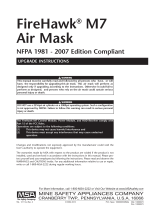
CYLINDER AND VALVE ASSEMBLY
*as approved by NIOSH
The cylinder valve includes a metal valve body, threaded
connection for filling and attachment of the Audi-Larm
Alarm, handwheel, safety disc (burst disc), and pressure
gauge.
The pressure gauge continuously shows the air pressure
in the cylinder.
The handwheel is used to open and close the cylinder
valve.
5TAL 708 (L) Rev. 1 - 10082858
Capacity Pressure Rated Svc*
Cubic Ft. psig Life (Min.)
45 4500 30
88 4500 60
45 2216 30
45 2216 30
60 3000 30
66 4500 45

AUDI-LARM ALARM WITH URC ASSEMBLY
The Audi-Larm Alarm rings when there is approximately
25% of the air mask’s rated service time remaining and
when the cylinder valve is first opened, providing an audi-
ble indication that the alarm is working properly.
A high pressure hose delivers air at cylinder pressure from
the Audi-Larm Alarm to the PR14 First Stage Regulator.
Note: The remaining service time calculations are based
on a 40 LPM (liters per minute) NIOSH breathing rate.
All FireHawk M7 Air Masks are equipped with an Audi-
Larm Alarm that includes a URC Assembly (Universal
Rescue Connection). The URC Assembly is a male quick-
fill inlet for use by Rapid Intervention Crews for emer-
gency filling of the SCBA or during transfill operations.
Also included with the URC Assembly is a pressure relief
valve for protection of the cylinder burst disc.
FIREHAWK M7 CARRIER AND HARNESS ASSEMBLY
DO NOT use this carrier and harness assembly as a
vertical raising or lowering device. Failure to follow
this warning can result in serious personal injury or
death.
The carrier consists of a backplate, a cylinder band with
latch to hold the cylinder, and a harness, consisting of
shoulder pads, chest strap (optional), adjustable pull straps,
waist belt, waist belt mounted regulator retainer, swiveling
lumbar pad (optional), and Rescue Belt (optional).
ULTRA ELITE FACEPIECE
The facepiece is available in three sizes (Small, Medium,
and Large).
The facepiece lens is super-hardcoated to meet the
requirements of NFPA 1981.
The facepiece has a low-resistance, pressure-demand
exhalation valve.
An inhalation check valve in the inlet housing keeps mois-
ture and contaminants out of the Firehawk Regulator.
The facepiece has a speaking diaphragm for clear com-
munication.
FIREHAWK M7 HUD
The FireHawk M7 HUD, located on the Ultra Elite
Facepiece allows a user to see cylinder pressure in one
quarter cylinder increments, PASS pre-alarms, battery sta-
tus, and telemetry information (optional) while wearing the
air mask.
FIREHAWK M7 CONTROL MODULE (PASS DEVICE)
The FireHawk M7 Control Module is the user’s interface
with the air mask.
The FireHawk M7 Control Module is equipped with an
analog gauge as well as an LCD to provide the user vital
information: numeric and iconic cylinder pressure, battery
status, thermal alarm (optional), and time remaining.
If the air mask is equipped with the optional FireHawk M7
Telemetry Module, the radio link status and evacuation
alarms are displayed.
The integrated PASS motion sensor is housed within the
FireHawk M7 Control Module.
FIREHAWK M7 POWER MODULE (PASS DEVICE)
The FireHawk M7 Power Module on the lower portion of
the backplate houses the batteries, serves as the cylinder
stop, emits audible PASS alarms, and has buddy lights.
The FireHawk M7 Power Module is linked to the FireHawk
M7 Control Module via the power cable.
OPTIONAL FIREHAWK M7 AIR MASK COMPONENTS
CLEAR COMMMAND COMMUNICATION SYSTEM
The Clear Command Communication System is an elec-
tronic speech projection system available with either an
amplifier or an amplifier with radio interface connection.
DESCRIPTION
6
TAL 708 (L) Rev. 1 - 10082858
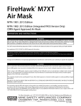
End of
Service
Cylinder Remaining Service Time
Time (Approx.) Indicator
Pressure
(Approx)
30 min. 2216 psi 7 minutes 530 psi
30 min. 3000 psi 10 minutes 750 psi
30 min. 4500 psi 7 minutes 1125 psi
45 min. 4500 11 minutes 1125 psi
60 min. 4500 psi 14 minutes 1125 psi

DESCRIPTION
FIREHAWK M7 TELEMETRY MODULE
The FireHawk M7 Telemetry Module provides the firefight-
er with two-way communication with Incident Command.
The firefighter’s vital statistics such as cylinder pressure,
service time remaining, PASS alarm, low battery alarm,
and thermal alarm are transmitted back to Incident
Command. Also, the firefighter has the ability to be evac-
uated remotely by Incident Command. The radio trans-
mitter is located inside of the FireHawk M7 Power
Module.
EXTENDAIRE SYSTEM
The ExtendAire System, located on the user’s left chest,
enables two users to share a common air supply during
emergency escape. The users can couple the Firehawk
Second Stage Regulator from one user to the intermedi-
ate pressure manifold of the other user. Both users will
receive intermediate pressure air from the donor's first
stage regulator and cylinder. The duration of the remaining
air supply will be reduced by at least half.
The SCBA is approved by NIOSH without inter-connecting
two users to one apparatus. NIOSH does not certify
“buddy breathers”. Therefore, the attachment of the
receiver's regulator to the donor's apparatus voids the
NIOSH approval for both air masks.
RESCUE BELT
The MSA Fire Service Rescue Belt is a personal escape
system integrated into an FireHawk M7 Carrier and
Harness Assembly. The system is designed to provide the
user a means of escape from an elevated position. Use of
the Rescue Belt must be in accordance with the user’s fire
department procedures. Care and use instructions are
provided under a separate manual, P/N 10052748.
7TAL 708 (L) Rev. 1 - 10082858


VISUAL INSPECTION AND FUNCTIONAL TESTS
INSPECTION
Conduct the Following: Before Use, After Each Use, and
Monthly
Thoroughly inspect this air mask upon receipt and before
use. This air mask is to be used only by trained and quali-
fied personnel. Read and understand these instructions
before attempting to use this equipment.
Inspect the entire air mask after it is cleaned and disin-
fected. NFPA-1500, as well as ANSI Standards Z88.2 and
Z88.5, describe three levels of inspection procedures
which are to be performed. Refer to these documents, or
to an inspection program prepared by a health profession-
al in establishing an inspection program.
If the air mask exhibits any of the conditions listed in
the Component Inspection section or if the air mask
does not function properly as described in the
Functional Tests section, the air mask must be
removed from service. Failure to follow this warning
can result in serious personal injury or death.
DO NOT inspect the air mask before cleaning if there
is danger of contacting hazardous contaminants.
Clean and disinfect first, then inspect. Failure to follow
this warning can cause inhalation or skin absorption
of the contaminant and result in serious personal
injury or death.
Never substitute, modify, add, or omit parts. Use only
exact replacement parts in the configuration as speci-
fied by the manufacturer. Failure to follow this warning
can result in serious personal injury or death.
COMPONENT INSPECTION
1. Facepiece
a. Inspect the facepiece for rubber deterioration, dirt,
cracks, tears, holes, or tackiness.
b. Inspect the head harness straps for tears, loss of
elasticity, or missing buckles or straps.
c. Inspect the lens for cracks, scratches, and a tight
seal with the facepiece rubber.
d. Ensure the exhalation valve is clean and operates
easily. The valve must move off the seat and return
when released.
e. Inspect the facepiece inlet for damage. Ensure the
spider gasket and valve disc are present.
f. Inspect the facepiece rubber behind the FireHawk
M7 HUD and/or Clear Command Communication
System bracket (optional) for holes or tears.
2. FireHawk M7 HUD
a. Inspect the FireHawk M7 HUD for cracks or other
signs of damage which could allow contaminants to
enter the housing.
b. Ensure that moisture or debris is not present in the
battery compartment.
c. Ensure the battery compartment o-ring on the bat-
tery cap is free of debris and not damaged or miss
ing.
d. Reassemble the FireHawk M7 HUD to the bracket
on the Ultra Elite Facepiece.
3. Clear Command Communication System
a. Remove the amplifier housing from the facepiece
and inspect the housing for cracks or other signs of
damage
b. Ensure that the battery compartment is free of
moisture or debris.
c. Reassemble the amplifier housing on the facepiece.
d. Depress the on/off button on the unit and then
release it.
e. Look through the facepiece lens. The red LED
should be illuminated at the top of the amplifier unit.
f. Scrape a fingernail lightly across the voicemitter
microphone grille of the voicemitter microphone
assembly.
g. Listen for this sound reproduced in the amplifier
speaker.
h. Depress and release the on/off button again to turn
the unit OFF. The LED on the amplifier unit should
be OFF.
4. Firehawk Second Stage Regulator
a. If the FireHawk M7 Air Mask is equipped with a
quick-connect second stage intermediate pressure
hose, inspect the rubber washer for deterioration,
dirt, cracks, tears, or tackiness.
5. PR14 First Stage Regulator
a. Inspect the regulator mounting bracket (attached to
the backplate) for cracks, weakened areas, or signs
of heat or chemical related damage.
b. Inspect the regulator mounting bracket screws to
ensure they are secure.
c. Inspect the regulator mounting bracket to ensure
that it holds the regulator securely.
d. Inspect the pressure relief valve. Ensure that the
relief holes are clear and free of debris or other con-
taminants. Ensure that the pressure relief valve is
properly secured.
e. Inspect the hose connections. Ensure that the
hoses are properly secured.
6. Audi-Larm Alarm
a. Unthread the Audi-Larm Alarm coupling nut from
the cylinder valve. Inspect the coupling nut for
thread damage.
b. Ensure there is an o-ring present and not damaged.
Replace the o-ring if it is damaged.
c. Ensure that the bell is properly aligned and that the
screws are tight. If the bell is loose, remove the
alarm from service.
d. Inspect the relief valve for damage. Ensure the relief
9TAL 708 (L) Rev. 1 - 10082858

VISUAL INSPECTION AND FUNCTIONAL TESTS
valve label is not damaged and that the relief valve
ports are not showing. If damaged, remove the air
mask from service and replace the relief valve.
e. Reattach Audi-Larm Alarm to the cylinder valve.
7. High Pressure Hose
a. Inspect the high pressure hose between the Audi-
Larm Alarm and the PR14 First Stage Regulator.
Look for cuts or severe abrasions. If damage is pre-
sent, replace the hose.
8. Cylinder and Valve Assembly
a. Air mask cylinders should be recharged as soon as
possible after use. Cylinders should not be stored
partially charged for two reasons:
• If used without recharge, the service life of the air
mask is reduced.
• The cylinder burst disc vents excess pressure if a
full cylinder is over exposed to fire or heat. If the
cylinder is not full, it may be damaged before the
burst disc vents.
b. If the cylinder is less than FULL (within 10% of
rated service pressure), recharge it before storage.
Cylinder air must be at least CGA Quality
Verification Level (Grade) D respirable air. In fire ser-
vice applications, MSA recommends breathing air
quality in accordance with NFPA 1989.
c. Inspect the cylinder valve for signs of damage. The
valve may be opened slightly to ensure it operates
properly. Be sure to fully close the valve.
d. Inspect the cylinder body for cracks, dents, weak-
ened areas, corrosive agents causing the fibers to
break or peel, or signs of heat-related damage. If
the cylinder is damaged return it to an MSA Service
Center.
e. Check the hydrostatic test date on the cylinder
approval sticker located on the cylinder neck.
Fiberglass composite cylinders must be tested
every three years. Carbon-wrapped and steel cylin-
ders must be tested every five years.
f. Ensure the needle and gauge face on the cylinder
valve gauge are clearly visible and that the gauge
stem is not bent.
It is also essential that the required inspections and tests
be performed on all air mask cylinders in accordance with
Department of Transportation (DOT) regulations. DOT reg-
ulations require that composite cylinders be retired from
service after the fifteenth year. This does not include cylin-
der valve assemblies that may be reused. Steel and alu-
minum cylinder service life is indefinite if proper inspec-
tion and hydrostatic test procedures are followed and they
indicate that the cylinder may remain in service. Contact
an MSA distributor or sales associate for more information
regarding this policy.
Note: ANSI Z88.5 recommends checking cylinder pres-
sure weekly. For maximum safety the cylinders should be
stored full or empty (pressure above ambient but less than
100 psi).
9. FireHawk M7 Carrier and Harness
a. Operate the latch wing on the cylinder band to
ensure that it opens and closes properly and that it
holds the cylinder securely. If the cylinder band and
latch is locked, the latch wing should not turn.
b. Inspect the back plate for cracks, weakened areas,
or signs of damage due to heat or chemical related
damage.
c. Inspect all harness components for cuts, tears,
abrasions, or signs of damage due to heat or chem-
ical related damage.
10. FireHawk M7 Control Module
a. Inspect the gauge hose and power cable for any
visible signs of damage.
b. Inspect for external cracks in the housing and
ensure the rubber cover is not damaged.
c. Ensure the buttons are not damaged or missing.
d. Ensure the gauge hose and power cable are
securely attached to the FireHawk M7 Control
Module.
11. FireHawk M7 Power Module
a. Inspect the FireHawk M7 Power Module housing for
external cracks and ensure that the FireHawk M7
Power Module, battery tube, and cylinder stop are
securely attached to the backplate.
b. Inspect the piezo emitters on both sides of the
FireHawk M7 Power Module. Ensure that the emit-
ter covers are not obstructed by dirt or debris.
c. Ensure that the power cable is securely attached to
the FireHawk M7 Power Module. The fitting on the
power cable should not be able to be unthreaded
by hand.
d. Remove the cap from the battery tube. Ensure that
the o-ring is properly installed on the battery cap, if
o-ring is missing, it must be replaced.
e. Inspect the inside of the battery tube. Ensure that
the battery terminals are not corroded and that the
tube if free of moisture and debris.
f. Replace the battery cap on the battery tube.
12. Record Keeping
a. Following inspection, the date and initials of the
designated inspector should be recorded on an
inspection tag. A more detailed record of the opera-
tions performed can be noted on an inspection and
maintenance log, available from MSA. When the
inspection data has been recorded, the air mask is
ready for use.
All repair and replacement of subassemblies must be
carried out by an MSA certified repair technician.
Failure to follow this warning will void NFPA and
NIOSH certifications and can result in serious person-
al injury or death.
10
TAL 708 (L) Rev. 1 - 10082858

VISUAL INSPECTION AND FUNCTIONAL TESTS
FUNCTIONAL TESTS
Conduct the Following: Before Use, After Each Use, and
Monthly
1. Check that the Firehawk Regulator and facepiece can
hold a negative pressure.
a. Close the cylinder valve and purge any air from the
system using the bypass knob on the Firehawk
Regulator.
b. Hold the facepiece against the face to create an
effective seal.
c. Attach the Firehawk Regulator to the facepiece and
inhale until the facepiece begins to collapse against
the face. Hold breath for approximately 10 seconds.
Negative pressure should be maintained and the
facepiece should remain collapsed against the face
for the entire 10 seconds.
d. Do not use the air mask if negative pressure cannot
be maintained in the facepiece. Return the Firehawk
Regulator and facepiece to a certified repairperson.
2. Check Firehawk Regulator operation.
Note: Firehawk Regulator functional checks must be con-
ducted with a full cylinder. Check the pressure gauge on
the cylinder valve to verify that the cylinder is full.
a. Push the release buttons on the side of the regula-
tor.
b. Ensure that the regulator bypass knob is fully
closed (clockwise).
c. Slowly open the cylinder valve to pressurize the air
mask. Ensure that the cylinder valve is completely
opened.
d. Open the Firehawk Regulator bypass knob (counter-
clockwise). Ensure that air flows from the regulator.
Close the bypass knob (clockwise).
e. Attach the regulator to the facepiece. Ensure proper
regulator attachment by pulling on the regulator.
f. Don the facepiece or hold the facepiece against the
face to create an effective seal.
g. Inhale sharply to start air flow. Breathe normally.
Ensure proper regulator response. The regulator
should not make any unusual sounds including
whistling, chattering, or popping.
h. Remove the facepiece from the face. Ensure that air
flows freely. Push the regulator release buttons.
Ensure that air flow stops.
i. If the regulator fails to meet any of the above
checks, remove the air mask from service. Return
the regulator to a certified repairperson.
3. FireHawk M7 HUD, FireHawk M7 Control Module,
FireHawk M7 Power Module, and Audi-Larm Alarm
a. Verify proper function of the FireHawk M7 HUD,
FireHawk M7 Control Module, FireHawk M7 Power
Module, and Audi-Larm Alarm by observing the
FireHawk M7 Control Module gauge and display
when the alarms ring and tone. Perform this test
with a minimum cylinder pressure of 1200 psi for
2216 psi air masks, 1800 psi for 3000 psi air masks,
and 2000 psi for 4500 psi air masks.
b. Pressurize the system by opening the cylinder
valve. Listen for the FireHawk M7 Power Module to
sound and for the Audi-Larm Alarm to ring briefly.
c. Look through the facepiece lens at the LED display
of the FireHawk M7 HUD, the LEDs must illuminate
through the startup sequence as the air mask is
pressurized:
oOne red LED on/off
o One orange LED on/off
o One yellow LED on/off
o Four green LED on/off
o Three green LED on/off
o Two yellow LED on/off
o One red LED ON on/off
d. Ensure that the alarm button on the FireHawk M7
Control Module and the buddy lights on the
FireHawk M7 Power Module are slowly flashing
green.
e. Allow the FireHawk M7 Control Module to remain
motionless for approximately 20 seconds. Listen for
the FireHawk M7 Power Module to sound the low
volume repeated tones of the PASS pre-alarm.
Verify that the alarm button on the FireHawk M7
Control Module and the buddy lights of the
FireHawk M7 Power Module are slowly flashing red.
Also verify that the orange LED is displayed in the
FireHawk M7 HUD. Ensure that the FireHawk M7
Control Module remains motionless until the full
PASS alarm activates. Listen for the FireHawk M7
Power Module to sound the loud PASS alarm. Look
for the alarm button on the FireHawk M7 Control
Module and the buddy lights on the FireHawk M7
Power Module to rapidly flash red.
f. Reset the PASS alarm by pressing the reset button
(yellow) on the side of the FireHawk M7 Control
Module two times within approximately one second.
g. To check the manual activation of the PASS alarm,
press and hold the alarm button on the front of the
FireHawk M7 Control Module for approximately
three seconds. Listen for the PASS alarm to be
emitted from the FireHawk M7 Power Module.
h. Reset the PASS alarm. Press the reset button (yel-
low) on the FireHawk M7 Control Module two times
within approximately one second.
i. Allow the FireHawk M7 Control Module to remain
motionless until the PASS pre-alarm sounds. Shake
the FireHawk M7 Control Module to reset the alarm.
j. If the FireHawk M7 Control Module and FireHawk
M7 Power Module pass these functional checks,
complete all remaining air mask donning steps of
this instruction manual.
k. Disconnect the Firehawk Regulator from the face-
piece.
l. Close the cylinder valve fully.
m.Slowly crack the bypass valve on the Firehawk
Regulator to bleed off pressure until the FireHawk
M7 Control Module pressure reading drops below
the following values:
11 TAL 708 (L) Rev. 1 - 10082858

VISUAL INSPECTION AND FUNCTIONAL TESTS
o 530 psi - approximately (2216 psi system)
o750 psi - approximately (3000 psi system)
o 1050 psi - approximately (4500 psi system)
Asingle flashing red LED must display in the FireHawk
M7 HUD at the appropriate pressure listed above. The
Audi-Larm Alarm will ring and the alarm button on the
FireHawk M7 Control Module and buddy lights on the
FireHawk M7 Power Module will flash red at this time.
n. The alarms should continue until the air pressure is
200 psi or less. If the Audi-Larm Alarm, FireHawk
M7 Control Module, FireHawk M7 Power Module, or
FireHawk M7 HUD does not function properly, the
air mask must be removed from service.
o. When the system pressure falls below 200 psi, turn
the FireHawk M7 Control Module off (sleep mode)
by pressing the reset button (yellow) two times with-
in approximately one second.
p. Open the bypass valve slowly to release any
remaining pressure in the system. Close the bypass
valve.
DO NOT disconnect the Audi-Larm Alarm coupling nut
when pressure is shown on the FireHawk M7 Control
Module gauge or display. Release all pressure from
the air mask by opening the Firehawk Regulator
bypass valve. Removing the coupling nut with the air
mask is pressurized can result in serious personal
injury, death, or damage to equipment.
12
TAL 708 (L) Rev. 1 - 10082858

DONNING
DONNING THE AIR MASK
1. Remove the facepiece from the case.
DO NOT use a cover lens in a high-temperature envi-
ronment, such as firefighting. High temperatures may
distort the cover lens. Or, moisture trapped between a
cover lens and the facepiece lens may condense and
distort vision. Always remove the cover lens before
donning the facepiece. Failure to follow this warning
can result in serious personal injury or death.
2. Ensure that the cylinder is fully pressurized.
3. Reach the right arm inside the right shoulder straps
and grasp the FireHawk M7 Control Module. Slide the
left arm through the left shoulder straps.
4. Bend forward slightly; resting the carrier on the back.
5. Attach the chest strap buckle (optional).
6. Fasten the waist belt and pull it tight for a snug fit.
Most of the air mask weight should be carried on the
hips.
7. Stand up straight. Pull the shoulder strap pull tabs out
to tighten the shoulder straps. Additional adjustments
to the waist belt may be needed.
8. The shoulder straps and waist strap ends must be
tucked in and lay flat across the body.
BEFORE USING THE AIR MASK
1. Grasp the Firehawk Regulator and push the side but-
tons.
2. Ensure that the red
bypass knob is fully
closed (clockwise).
3. Reach behind and fully
open the cylinder valve.
Listen for any hiss or pop sounds from the Audi-Larm
Alarm, if heard, do not use the air mask. Return it to
an MSA trained or certified repairperson. Failure to
follow this warning can result in serious personal
injury or death.
4. As the system pressure rises from 50 to 200 psi, both
visible and audible alerts activate automatically, indi-
cating that the air mask is functioning properly. Such
alerts include a brief ring from the Audi-Larm Alarm, a
chirp from the FireHawk M7 Power Module, and the
start-up sequence of the FireHawk M7 HUD LEDs.
DO NOT use the air mask if the Audi-Larm Alarm fails
to ring, the FireHawk M7 Power Module fails to sound,
or the FireHawk M7 HUD fails to light, The air mask
must be checked and corrected for proper operation
by an MSA trained or certified repairperson before
using. Failure to follow this warning can result in seri-
ous personal injury or death.
5. No air should flow from
the Firehawk Regulator.
If it does, repeat steps
1 and 2.
6. Ensure the FireHawk M7 HUD and FireHawk M7
Control Module pressure indicators show a full cylin-
der.
DO NOT use the air mask if the cylinder gauge and
FireHawk M7 Control Moedule pressure readings are
not within 5% (110/2216 psi, 150/3000 psi, 225/4500
psi) of full cylinder pressure. Send the unit to an MSA
certified repair person.
13 TAL 708 (L) Rev. 1 - 10082858

DONNING
7. Check the Firehawk
Regulator’s bypass
operation. Grasp the
red knob and turn it
counter-clockwise.
Listen for airflow and
then turn it to the off
position.
8. Fully close the cylinder valve.
9. Listen for air leaks and watch the pressure gauge and
display on the FireHawk M7 Control Module for 10
seconds.
DO NOT use the air mask if the pressure drops more
than 100 psi in ten seconds, The air mask must be
repaired; otherwise, reduced service life may result.
10. Crack the Firehawk Regulator bypass valve slowly to
bleed off pressure until the FireHawk M7 HUD and
FireHawk M7 Control Module displays drop below:
530 psi-approximately (2216 psi system)
750 psi-approximately (3000 psi system)
1125 psi-approximately (4500 psi system)
At these pressures the FireHawk M7 HUD should display
a flashing red LED, the Audi-Larm Alarm should ring con-
tinuously, and the alarm button on the FireHawk M7
Control Module and the buddy lights on the FireHawk M7
Power Module should be flashing red.
11. When the system pressure falls below 200 psi, turn
the FireHawk M7 Control Module off by depressing
the reset button (yellow) two times within approxi-
mately one second.
DO NOT use the air mask if the Audi-Larm Alarm fails
to ring or fails to continuously ring down to pressures
of 200 psi, or if the FireHawk M7 Control Module or
FireHawk M7 HUD fails to light properly. The air mask
must be checked and corrected for proper operation
by an MSA trained or certified repairperson before
using. Failure to follow this warning can result in seri-
ous personal injury or death.
Note: The FireHawk M7 HUD will automatically turn itself
OFF approximately 60 seconds after the air mask has
been depressurized. A single red LED will flash until the
device turns off.
DONNING THE FACEPIECE
Note: Before donning, ensure that the Firehawk Regulator
sealing ring is seated properly in its groove on the outlet
of the regulator and that it is not torn, gouged, or nicked.
1. Loosen all the harness
straps. Grip the bottom
straps.
2. Insert chin into the
lower part of facepiece,
then pull the harness
back over the head.
3. Pull the back of har-
ness downward until
centered at the back of
the head.
4. Tighten the two lower
straps first by pulling
them straight back, not
out. Tighten the face-
piece until the mask is
snug against the face.
14
TAL 708 (L) Rev. 1 - 10082858

DONNING
5. Tighten the two side
temple straps in the
same manner as
described in step 4.
Ensure that the face-
piece tabs are not
tucked under the face
seal.
6. Ensure the back of the
harness is centered on
the back of the head
and that the facepiece
seal provides uniform
pressure on the face at
all points. Readjust the
straps if needed.
FACEPIECE FIT CHECK
Note: Check the inhalation valve by inhaling. If the face-
piece does not provide sufficient flow of air, do not use
facepiece. The facepiece must be repaired or replaced.
1. Check facepiece fit,
a. Hold the palm of the hand over the facepiece inlet
adapter.
b. Take a deep breath
and hold it for at
least 10 seconds.
The facepiece
should collapse and
stay collapsed
against the face. If it
does not, readjust
the facepiece and
test again. If this
does not correct
the leak, do not use
the facepiece.
2. Test the exhalation valve.
a. Take a deep breath and hold it.
b. Block the facepiece inlet adapter with the palm of
the hand and exhale. If the exhalation valve is stuck,
a heavy rush of air around the facepiece may be
noticed. A sharp exhalation of air may be needed to
open the valve. If this does not release the valve, do
not use the facepiece.
This device may not seal properly to the face if a
beard, gross sideburns or similar physical characteris-
tics (see NFPA-1500 and ANSI Z88.2) exist. An improp-
er facial seal may allow contaminants to leak into the
facepiece, reducing or eliminating respiratory protec-
tion. Do not use this device if such conditions exist.
The face-to-facepiece seal must be tested before
each use. Never remove the facepiece except in a
safe, non hazardous non-toxic atmosphere. Failure to
follow this warning can result in serious personal
injury or death.
3. Open the cylinder valve
fully. Push in on the
side buttons of the
Firehawk Regulator to
stop air flow.
4. Listen for any hissing or popping sounds from the
Audi-Larm Alarm. If heard, return the air mask to an
MSA trained or certified repairperson.
INSTALLING THE SLIDE-TO-CONNECT FIREHAWK
REGULATOR ON THE FACEPIECE
Note: The slide-to-connect regulator has a side button
with a two pronged fork protruding from it. If this “fork” is
not present refer to the Installing the Push-To-Connect
Firehawk Regulator section of this manual.
1. Grasp and orient the
regulator so that red
bypass knob is point-
ing to the right and
slide button is on top.
15 TAL 708 (L) Rev. 1 - 10082858

DONNING
2. Slide the regulator onto
the rail of the facepiece
cover. Slide the regula-
tor down the rail until
the regulator stops.
3. Insert the regulator into
the facepiece inlet by
pushing inward.
4. Ensure proper engagement by pulling on the regulator
to verify that the regulator is securely attached to
facepiece.
DO NOT use the air mask unless the Firehawk
Regulator is connected properly. A regulator that is
not installed correctly can separate from the facepiece
unexpectedly. Return the air mask to an MSA trained
or certified repairperson to correct the condition.
Failure to follow this warning can result in serious per-
sonal injury or death.
5. Inhale sharply to start the airflow.
a. Check the bypass again by turning the red knob
counter-clockwise until feel increased airflow is felt.
Close the bypass.
There must be a continuous flow of air when the
bypass knob is opened. If not, do not use the air
mask. The air mask must be checked and the condi-
tion corrected by an MSA trained or certified repair-
person before it can be used. Failure to follow this
warning can result in serious personal injury or death.
Note: If the air mask passes all tests, it is ready for use.
These tests must be performed every time before entering
a hazardous atmosphere. If the air mask fails to meet any
of the tests, the condition(s) must be corrected before
using the air mask.
INSTALLING THE PUSH-TO-CONNECT FIREHAWK
REGULATOR
Note: There are two versions (slide-to-connect and push-
to-connect) of the Firehawk Regulator available for the
FireHawk M7 Air Mask. A slide-to-connect Firehawk
Regulator can be identified by examining the side buttons.
The slide-to-connect has a side button with a two
pronged fork protruding from it. If this “fork” is present,
refer to Installing the Slide-To-Connect Firehawk
Regulator section.
1. Grasp the Firehawk Regulator and insert the regulator
into the facepiece by pushing inward. Check proper
engagement by pulling on the regulator to ensure that
the regulator is securely attached to facepiece.
DO NOT use the air mask unless the regulator is con-
nected properly. A regulator that is not installed cor-
rectly can separate from the facepiece unexpectedly.
Return the air mask to an MSA trained or certified
repairperson to correct the condition. Failure to follow
this warning can result in serious personal injury or
death.
2. Inhale sharply to start the airflow.
3. Check the bypass again by turning the red knob
counter-clockwise until increased air flow is felt. Close
the bypass.
There must be a continuous flow of air when the
bypass knob is opened. If not, do not use the air
mask. The air mask must be checked and the condi-
tion corrected by an MSA trained or certified repair-
person before it can be used. Failure to follow this
warning can result in serious personal injury or death.
Note: If the air mask passes all tests, it is ready for use.
These tests must be performed every time before entering
a hazardous atmosphere. If the air mask fails to meet any
of the tests, the condition(s) must be corrected before
using the air mask.
16
TAL 708 (L) Rev. 1 - 10082858

USING THE AIR MASK
PRECAUTIONS DURING USE
Note: If the breathing apparatus or any component fails,
malfunctions, or becomes damaged, contact MSA at 1-
800-MSA-2222 [1-800-672-2222] or email customer ser-
vice at [email protected]. SCBA products may be con-
sidered hazardous material. In addition, U.S. Department
of Transportation exceptions and approvals may apply to
SCBA products. Please contact customer service at
1-800-MSA-2222, or visit www.MSAnet.com/prism, for
more information.
Periodically check the pressure indicated on the FireHawk
M7 Control Module.
• Air flow in the air mask is reduced: Immediately open
the Firehawk Regulator bypass. Immediately return to
fresh air.
• Air mask free-flows: Immediately return to fresh air.
• Audi-Larm Alarm Rings: Immediately return to fresh
air.
• FireHawk M7 HUD low pressure indicator lights and
flashes red: Immediately return to fresh air.
• FireHawk M7 Control Module alarm button flashes
red: Immediately return to fresh air.
Periodically check the pressure indicated on the FireHawk
M7 HUD and FireHawk M7 Control Module during use.
The FireHawk M7 Control Module continually displays the
cylinder pressure while the FireHawk M7 HUD indicates
when each quarter of the total cylinder pressure has been
reached for 20 seconds. When the needle on the
FireHawk M7 Control Module gauge reaches the red zone
on the gauge face the Audi-Larm Alarm will begin ringing,
the FireHawk M7 HUD will display a single flashing red
LED, and the alarm button on the FireHawk M7 Control
Module and buddy lights on the FireHawk M7 Power
Module will flash red. When the Audi-Larm Alarm starts
ringing or when the pressure reaches approximately 25%
of the rated service pressure, return to fresh air.
The FireHawk M7 HUD, FireHawk M7 Control Module,
and Audi-Larm Alarm indicate when cylinder pressure
drops below these approximate values:
530 psi-approximately (2216 psi system)
750 psi-approximately (3000 psi system)
1125 psi-approximately (4500 psi system)
When the FireHawk M7 HUD, FireHawk M7 Control
Module, or Audi-Larm Alarm indicates 25% cylinder pres-
sure, immediately return to fresh air.
Note: Air mask service life is greatly reduced when the
Firehawk Regulator bypass is used.
Leave the contaminated area immediately if:
• Breathing becomes difficult
• Dizziness or other distress occurs
• You taste or smell the contaminant
•You experience nose or throat irritation
• SCBA not functioning according to the
instructions or training
Failure to follow this warning can result in serious per-
sonal injury or death.
Note: See NIOSH Approval Label, Inserted in the Users
Instructions for complete list of CAUTIONS and LIMITA-
TIONS for the Respirator.
Misuse or abuse of the FireHawk M7 HUD, the
FireHawk M7 Control Module, FireHawk M7 Power
Module, or the equipment to which they are attached,
or using this equipment in a manner or situation not
intended by the manufacturer, may result in damage to
the equipment or may result in personal injury or
death to user or persons dependent on the user or
damage to the equipment.
• Always inspect the FireHawk M7 HUD, FireHawk
M7 Control Module, and FireHawk M7 Power
Module for damage before use. If damage is found,
immediately remove the device from service.
• DO NOT alter these components. Altering will void
the Intrinsic-Safety rating and may affect the
Intrinsic-Safety of the device.
FIREHAWK M7 HUD
FIREHAWK M7 HUD FUNCTIONALITY
1. The FireHawk M7 HUD allows the user to see the
cylinder pressure while wearing the air mask. The
FireHawk M7 Control Module wirelessly transmits a
signal to the FireHawk M7 HUD (on the facepiece)
while the air mask is in use. The FireHawk M7 HUD
displays the cylinder pressure in one quarter cylinder
increments, by an LED pattern.
• As each quarter cylinder pressure has been
reached, a unique LED pattern will be displayed for
approximately 20 second before extinguishing. The
display can be refreshed by pressing and holding
the mode button (green) on the FireHawk M7
Control Module for approximately three seconds.
• When 25% of the rated service pressure has been
reached, a single flashing red LED will be displayed
and will continue to flash until the unit is turned off
or the cylinder has be refilled.
• The FireHawk M7 HUD must be within approximate-
ly 18 inches of the FireHawk M7 Control Module to
properly receive the signal being transmitted.
2. The FireHawk M7 HUD has a buddy light that flashes
17 TAL 708 (L) Rev. 1 - 10082858

USING THE AIR MASK
18
TAL 708 (L) Rev. 1 - 10082858
red when the air mask has reached 25% of the rated
service pressure. This buddy light is not visible to the
user while the air mask is in use.
3. When the user of the air mask remains motionless for
approximately 20 seconds, the PASS pre-alarm will
begin to sound. During this pre-alarm, the FireHawk
M7 HUD will display an orange LED, and this LED will
extinguish when full PASS alarm has been reached or
the pre-alarm has been reset.
4. When an evacuation command has been sent to the
user (if the optional FireHawk M7 Telemetry Module is
in use), the FireHawk M7 HUD will display an alternat-
ing red and orange LED until the evacuation has been
confirmed.
5. The FireHawk M7 HUD has a photo sensor that auto-
matically adjusts the brightness of the LEDs based on
the intensity of the ambient light measured outside of
the facepiece.
6. The FireHawk M7 HUD indicates a low battery condi-
tion by a single flashing yellow LED. When the
FireHawk M7 Power Module reaches a low battery
condition, a double flash of the yellow LED will be dis-
played in the FireHawk M7 HUD. If both the FireHawk
M7 HUD and FireHawk M7 Power Module have
reached a low battery condition, the FireHawk M7
HUD will display an alternating single and double flash
of the yellow LED. If this condition exists, return to
fresh air, and replace the batteries immediately. See
Replacing Batteries in the FireHawk M7 HUD.
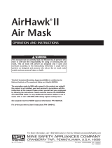
Refer to Chart 1 for a full description of all FireHawk M7
HUD LED patterns.
Replacing the Batteries in the FireHawk M7 HUD
Replace the batteries in the FireHawk M7 HUD when
the low battery LED flashes. Use only recommended
battery types. Change the batteries in a non-haz-
ardous area only. Failure to follow this warning can
result in serious personal injury or death.
1. Unthread the battery cap (counter-clockwise) on the
FireHawk M7 HUD battery tube.
2. Remove the battery cartridge from the FireHawk M7
HUD.
3. Remove the batteries and discard.
3. Inspect the battery cartridge for signs of damage such
as corrosion on the battery terminals or cracks in the
cartridge. If the battery cartridge is damaged, replace
the cartridge immediately.
4. Insert three AAA alkaline batteries in the appropriate
locations on the cartridge. Follow the notations on the
cartridge to ensure proper battery orientation.
R
GG
G
Y
G
G
G
G
Y
76% to 100%
Full Cylinder, 4 Green LED
20 Sec. Steadily ON
75% to 51%
3/4 Full Cylinder, 3 Green LED
20 Sec. Steadily ON
26% TO 50%
1/2 Full Cylinder, 2 Yellow LED
30 Sec. Flashing ON/OFF
25% to 0%
1/4 Full Cylinder, 1 Red LED
Flashing Continuously
Yellow LED, Low Battery LED
Single Flash - M7
Double Flash - M7 Power Module
Alternating Single/Double Flash -
Both M7 HUD and M7 Power Module
YR O
Orange LED
for PASS Pre-Alarm
Red/Orange LED for Evacution Signal
Alternating Red/Orange
(M7 Telemetry Model)
Chart 1: FireHawk M7 HUD LED Patterns

USING THE AIR MASK
Use only Rayovac 824 LR03, Rayovac Ultrapro 4R03,
Energizer E92, Endergizer Industrial EN92, Duracell
MN2400, or Duracell Process MN2400 alkaline batter-
ies in the FireHawk M7 HUD. Use of other batteries, or
acombination of batteries from different manufactur-
ers, will affect the performance of unit and void the
Intrinsic Safety Approval.
5. Insert the battery cartridge into the battery tube on the
FireHawk M7 HUD.
6. Before installing the battery cap, verify that the o-ring
is in place and free of damage and debris. If the o-ring
is missing or damaged, replace O-ring. Failure to do so
may allow moisture or contaminants into the battery
tube and cause the device to not function properly.
7. Thread the battery cap on to the battery tube of the
FireHawk M7 HUD (clockwise). Hand-tighten cap until
snug. Do not over-tighten battery cap.
8. As the battery cap makes contact with the battery car-
tridge, verify that the FireHawk M7 HUD display turns
on and goes through its start up sequence before
turning off. The yellow LED should not be flashing.
Battery Disposal/Recycling
Dispose of or recycle batteries in accordance with all
applicable federal, state, and local regulations.
DO NOT dispose of the batteries in fire. They may
explode. Failure to follow this warning can result in
serious personal injury or death.
Assembly of the FireHawk M7 HUD to the Facepiece
Bracket
Note: Assemble the FireHawk M7 HUD to the facepiece
bracket before donning the air mask.
With the facepiece lying on its side:
1. Align the metal tab on the FireHawk M7 HUD with the
metal plate on the front edge of the bracket.
2. Rotate the FireHawk M7 HUD so that the tab falls into
the slot behind the thumbscrew.
3. Thread the thumbscrew into the tab to finger-tight.
DO NOT use a screwdriver to tighten the thumbscrew.
Functional Tests
Note: Refer to the Visual Inspection and Functional Test
section of this manual.
Always test the FireHawk M7 HUD and the entire air
mask to be sure that the system operates properly
before entering any hazardous atmosphere. DO NOT
use this device unless it passes all inspection and
functional tests. Failure to follow this warning can
result in serious personal injury or death.
FIREHAWK M7 CONTROL MODULE FUNCTIONALITY
• The FireHawk M7 Control Module is assembled to the
gauge line hose and is connected to the FireHawk M7
Power Module by the power cable. The FireHawk M7
Control Module serves as the user interface with the
air mask and it also serves as the wireless transmitter
for the FireHawk M7 HUD.
• The FireHawk M7 Control Module has three control
buttons.
o The RESET/OFF button (yellow) on the side of the
FireHawk M7 Control Module resets the PASS
device from the full alarm mode. It also shuts the
unit off after the cylinder valve has been closed and
all pressure is bled from the system. When the
optional FireHawk M7 Telemetry Module is used,
the Reset button allows the user to confirm an
evacuation command.
o The center lighted ALARM button (green/red) acti-
vates the full PASS alarm with or without air pres-
sure.
o The top MODE button (green) will refresh the dis-
play in the FireHawk M7 HUD, activate the backlight
on the display of the FireHawk M7 Control Module,
set the FireHawk M7 HUD to continuous display
mode, and toggle the FireHawk M7 Control Module
digital display mode between pressure remaining
and calculated service time remaining. When the
FireHawk M7 Control Module is OFF, the mode but-
ton (green) can be used to scan an ID Tag into the
unit (when optional FireHawk M7 Telemetry Module
is used).
• The FireHawk M7 Control Module turns on automati-
cally when the user opens the air mask cylinder valve.
As the system pressure reaches approximately 200
psi, both visible and audible alarms activate automati-
cally, indicating that the unit is functional (audible
alarms are emitted from the FireHawk M7 Power
Module located on the backplate). The unit remains in
monitor mode until the user closes the cylinder valve,
purges the system pressure, and presses the reset
button (yellow) on the side of the FireHawk M7 Control
Module two times within approximately one second.
• While the air mask is in use, if the user is motionless
for approximately 20 seconds, the PASS (FireHawk
M7 Control Module and FireHawk M7 Power Module)
enters pre-alarm. During pre-alarm, the FireHawk M7
Power Module sounds 3 progressively louder tones
and the alarm button on the center of the FireHawk
M7 Control Module and buddy lights on the FireHawk
19 TAL 708 (L) Rev. 1 - 10082858

USING THE AIR MASK
M7 Power Module slowly flash red. Also, during the
PASS pre-alarm, an orange LED will be displayed in
the FireHawk M7 HUD. Movement of the FireHawk M7
Control Module cancels the PASS pre-alarm.
• If the user remains motionless for 30 seconds (approx-
imately), the PASS enters full alarm. During full PASS
alarm, the FireHawk M7 Power Module repeatedly
sounds two high-pitched tones followed by a buzz.
During full PASS alarm the alarm button on the
FireHawk M7 Control Module and the buddy lights on
the FireHawk M7 Power Module rapidly flash red.
•The PASS can be set into full alarm at any time (even
without air pressure) by pressing and holding the
alarm button on the FireHawk M7 Control Module.
• The PASS function uses red and green LEDs behind
the alarm button of the FireHawk M7 Control Module
and buddy lights on the FireHawk M7 Power Module
to display its status visually:
oGreen LEDs start to flash when the cylinder valve is
opened and shows that the device is operational.
20
TAL 708 (L) Rev. 1 - 10082858
ACTION VISIBLE/AUDIBLE INDICATOR VISIBLE INDICATOR,
without Thermal Alarm with Thermal Alarm CONTROL MODULE
automatic activation with
the system pressurized
manual activation
sensing mode (with or
without pressure
pre-alarm with
or without
pressure
full alarm (with or without
pressure)
deactivation
of full alarm
deactivation of pre-alarm
(with shake or move unit)
low battery
thermal alarm activation
(see thermal alarm activa-
tion curve)
radio link with
base station*
evacuation signal received*
redundant alarm (cylinder
pressure is below 25% of
rated service pressure
single rising tone with bee-
bop
start-up single rising tone
with bee-bop (also full
alarm)
none
low volume rising tone
medium volume buzz
high volume rise tone fol-
lowed by buzz
two high volume tones fol-
lowed by buzz
Bee
none
1 beep every 5 seconds
N/A
none
none
continuous beep beep
none
single rising tone with bee-
bop
start-up single rising tone
with bee-bop (also full
alarm)
none
low volume rising tone
medium volume buzz
high volume buzz followed
by buzz
two high volume tones fol-
lowed by buzz
Bee
none
1 beep every 5 seconds
1 beep every 3 seconds
none
none
continuous beep beep
none
green/red LED flash front
panel
green/red LED flash front
panel - red light flashing
green LED flashed
red LED flashes
red LED flashes
red LED flashes
green LED flashes
green LED flashes
empty battery icon on dis-
play
flashing thermometer icon
on display
radio link indicator icon in
upper left corner of display
radio link indicator icon dis-
appears
flashing “running man” icon
appears on display
red LED flashes
first 4 sec-
onds
(approx.)
second 4
seconds
(approx.)
last 4 sec-
onds
(approx.)
first push
of reset
button
second
push of
reset but-
ton
link is
established
out of
range
Chart 2: Audible/Visible Indicators, FireHawk M7 Power Module
*Action only available when the FireHawk M7 Telemetry Module is used.
/