Page is loading ...

1
Tempest i5000VF
///
S5370
Version 1.2
Copyright
Copyright © TYAN Computer Corporation, 2006. All rights reserved. No part of
this manual may be reproduced or translated without prior written consent from
TYAN Computer Corp.
Trademark
All registered and unregistered trademarks and company names contained in
this manual are property of their respective owners including, but not limited to
the following.
TYAN, Tempest i5000VF are trademarks of TYAN Computer Corporation.
Intel, Blackford-VS, and combinations thereof are trademarks of Intel
Corporation.
Phoenix, Phoenix-AwardBIOS are trademarks of Phoenix Technologies.
Microsoft, Windows are trademarks of Microsoft Corporation.
SuSE,is a trademark of SuSE AG.
IBM, PC, AT, and PS/2 are trademarks of IBM Corporation.
Notice
Information contained in this document is furnished by TYAN Computer
Corporation and has been reviewed for accuracy and reliability prior to printing.
TYAN assumes no liability whatsoever, and disclaims any express or implied
warranty, relating to sale and/or use of TYAN products including liability or
warranties relating to fitness for a particular purpose or merchantability. TYAN
retains the right to make changes to product descriptions and/or specifications
at any time, without notice. In no event will TYAN be held liable for any direct or
indirect, incidental or consequential damage, loss of use, loss of data or other
malady resulting from errors or inaccuracies of information contained in this
document.

2
Table of Contents
Check the box contents! 3
Chapter 1: Introduction
1.1 Congratulations…………………………………………………………… 5
1.2 Hardware Specifications………………………………………………… 5
Chapter 2: Board Installation
2.1 Board Image……………………………………………………………… 8
2.2 Block Diagram……………………………………………………………. 9
2.3 Board Parts, Jumpers and Connectors………………………………... 10
2.4 Tips on Installing Motherboard in Chassis…………………………….. 19
2.5 Installing the Processor(s)………………………………....................... 20
2.6 Installing the Memory……………………………………………………. 23
2.7 Attaching Drive Cables………………………………………………….. 25
2.8 Installing Add-in Cards………………………………............................ 27
2.9 Connecting External Devices…………………………………………… 28
2.10 Installing the Power Supply……………………………………………... 29
2.11 Finishing up………………………………………………………………. 29
Chapter 3: BIOS Setup
3.1 About the BIOS…………………………………………………………… 31
3.2 BIOS Main Menu…………………………………………………………. 33
3.3 Advanced Menu………………………………………………………….. 41
3.4 Security Menu…………………………………………………………….. 55
3.5 Power Menu………………………………………………………………. 56
3.6 Boot Menu………………………………………………………………… 57
3.7 Exit Menu…………………………………………………………………. 58
Chapter 4: Diagnostics
4.1 Beep Codes………………………………………………………………. 59
4.2 Flash Utility……………………………………………………………….. 59
4.3 BIOS Post Code………………………………………………………….. 60
Appendix I: SMDC Information
Appendix II: How to Make a Driver Diskette
Glossary

3
Check the box contents!
1x S5370 motherboard
1x 34-Pin floppy drive cable
1 x Ultra-DMA-133/100/66/33 IDE cable
3 x Serial ATA power cable
6 x Serial ATA Cable
1 x USB2.0 cable
1 x S5370 user’s manual
1 x S5370 Quick Reference guide
1 x TYAN driver CD
1 x I/O shield
2 x CPU Back Plane
If any of these items are missing, please contact your vendor/dealer for
replacement before continuing with the installation process.

4

5
Chapter 1: Introduction
1.1 - Congratulations
You have purchased one of the most powerful server solutions. The Tempest
i5000VF (S5370) is a flexible Intel
®
platform for multiple applications, based on
Intel
®
“Blackford-VS” MCH and ESB2 chipsets.
Designed to support Intel
®
Xeon 5000/5100/5300 series processor and 16GB
DDR2-533/667 FB-DIMM memory, and featured with integrated Dual Gigabit
Ethernet LAN, built-in 16MB XGI XG20
TM
video plus six serial ATA ports, the
S5370 offers exceptional performance and versatile solution for your server
platform.
Remember to visit TYAN’s Website at http://www.TYAN.com. There you can
find information on all of TYAN’s products with FAQs, online manuals and BIOS
upgrades.
1.2 - Hardware Specifications
Processor
•Dual LGA771 sockets
•Supports up to two Intel
®
Xeon
5000/5100 series processors
•Supports up to two Intel
®
Xeon
5300 series processors
•667/1066/1333 MHz FSB
•VRD 11.0
Chipset
•Intel
®
“Blackford-VS” MCH+ESB2
chipset
•SMSC SCH5017 super I/O chip
Memory
•Four 240-pin DDR2 FBDIMM
sockets
•2 memory channels
•Supports ECC DIMMs
•Maximum of 16/8GB DDR2-
533/667 FB-DIMM*
Integrated LAN Controllers
•Intel
®
Gigabit from ESB2
(w/”Gilgal”) (ASF2.0 option)
•Two front panel LED headers
(Link/Act)
•Two RJ-45 port with LEDs
Integrated Video Controller
•XGI XG20
•PCI interface
•16MB DDR memory
Integrated SATA 2.0 Controller
•Six SATA2.0 ports from Intel
ESB2
•Integrated RAID 0/1/5/10 support
BIOS
•Phoenix
®
BIOS on 8Mbit Flash
ROM
•Supports ACPI 1.0b

6
*FB-DIMM: Fully Buffered DIMM
Expansion Slots
•Two (2) PCI-Express x8 slots
(with x4 signal)
•One (1) PCI-X 133/100MHz slot
•Two (2) PCI 32-bit 33MHz slots
Total Five expansion slots from
ESB2
Integrated I/O
•One (1) 9-pin 16550 UART serial
port
•One (1) 15-pin VGA port
•Eight (8) USB2.0 ports (two ports
at rear, three front headers
support six ports)
•PS/2 mouse and keyboard
connectors
•One (1) FDD connector
•One (1) IDE connector supports
ATA100
•Six standard/integrated SATA
connectors
•Two side by side RJ-45
10/100/1000 LAN ports
System Management
•Winbond W83793G Hardware
Monitor ASIC
•CPU thermal & voltage monitor
support
•2-pin chassis intrusion header
•4-pin fan monitoring header
•Five (5) fan headers with
Tachometer and auto fan control
(4-pin configuration)
•Serial Console Redirect
•PXE via Ethernet, USB device
boot
•User-configurable H/W monitoring
•Auto-configuration of hard disk
types
•Multiple boot options
•48-bit LBA support
Form Factor
•SSI/CEB 1.01 (12” x 10.5”)
•EPS12V/SSI (24+8pin) power
connectors
•Stacked PS/2 keyboard and
mouse connectors
•Stacked USB2.0 (2) connectors
•Serial (1) and VGA (1) connectors
•Two side-by-side RJ-45 LAN
connectors with LEDs

7
Chapter 2: Board Installation
You are now ready to install your motherboard. The mounting hole pattern of
the Tempest i5000VF S5370 matches the ATX specification. Before continuing
with installation, confirm that your chassis supports an ATX motherboard.
How to install our products right… the first time
The first thing you should do is reading this user’s manual. It contains important
information that will make configuration and setup much easier. Here are some
precautions you should take when installing your motherboard:
(1) Ground yourself properly before removing your motherboard from the
antistatic bag. Unplug the power from your computer power supply and
then touch a safely grounded object to release static charge (i.e. power
supply case). For the safest conditions, TYAN recommends wearing a
static safety wrist strap.
(2) Hold the motherboard by its edges and do not touch the bottom of the
board, or flex the board in any way.
(3) Avoid touching the motherboard components, IC chips, connectors,
memory modules, and leads.
(4) Place the motherboard on a grounded antistatic surface or on the
antistatic bag that the board was shipped in.
(5) Inspect the board for damage.
The following pages include details on how to install your motherboard into your
chassis, as well as installing the processor, memory, disk drives and cables.
NOTE
DO NOT APPLY POWER TO THE BOARD IF IT HAS BEEN
DAMAGED

8
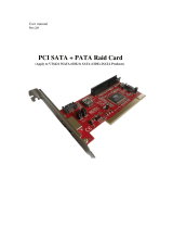
2.1- Board Image
This picture is representative of the latest board revision available at
the time of publishing. The board you receive may or may not look
exactly like the above picture.

9
2.2 - Block Diagram
Tempest i5000VF S5370 Block Diagram

10
2.3 - Board Parts, Jumpers and Connectors
DIMM 2
DIMM 1
DIMM 0
CN1
CN3
KB/MS
USB x 2
COM1
VGA
LAN1
LAN2
CN23
CN22
BIOS
PCIE1
PCIE3
PCIX1
BMC1
PCI1PCI1
PCI2
CN12
JP16
CN26
SATA0
SATA1
SATA4
SATA2 SATA5
SATA3
CN15
CN19
JP9
CN20
CN28
CN25
CN14
CN24
Intel
BF-VS MCH
Intel
ESB2
JP5
Intel
BF-VS MCH
Intel
BF-VS MCH
CPU1
CPU0
DIMM 3
CN21
This diagram is representative of the latest board revision available at the time of
publishing. The board you receive may not look exactly like the above diagram.

11
Jumper Legend
OPEN - Jumper OFF, without jumper cover
CLOSED – Jumper ON, with jumper cover
Jumper/Connector Function
JP5 Clear CMOS Jumper
JP9 IPMB Connector
JP16 Video Disable Jumper
CN1/CN3 EPS 12V Power Supply Connector
CN11 COM1 Port
CN12 Floppy Connector
CN13 Keyboard/Mouse Connector
CN14 IDE Connector
CN15/CN25/CN28 USB Header
CN19 Front Panel Header
CN20/CN21 CPU Fan Connectors
CN22/CN23/CN24 Chassis Fan Connectors
CN26 SMDC Connector
CN27 Onboard Video Connector

12
JP16 JP5
JP9

13
JP5: Clear CMOS Jumper
3
1
Normal
(Default)
3
1
Clear
Use this jumper when you forgot your system/setup
password or need to clear system BIOS setting.
How to clear the CMOS data
- Power off system and disconnect power
supply from AC source
- Use jumper cap to close Pin_2 and 3 for
several seconds to Clear CMOS
- Replace jumper cap to close Pin_1 and 2
Reconnect power supply to AC source
Power on system
JP16: Video Disable Jumper
3
1
(Default)
Enable the video function.
3
1
Disable the video function.
JP9: IPMB Connector
1
Pin 1 IPMB
DATA
Pin 2 GND
Pin 3 IPMB
CLK
Pin 4 NC

14
CN15 CN28
CN25
CN26

15
CN15: Front Panel USB2.0 Connector (used alone or with CN28/CN25)
2 1 0
1
9
Signal Pin Pin Signal
USB PWR
1 2
USB PWR
USB_P6_N_FB
3 4
USB_P7_N_FB
USB_P6_FB
5 6
USB_P7_FB
GND
7 8
GND
Key
9 10
GND
Use these headers to connect to the USB devices
via the enclosed USB cable.
CN28: Front Panel USB2.0 Connector (used alone or with CN15/CN25)
2 1 0
1
9
Signal Pin Pin Signal
USB PWR
1 2
USB PWR
USB_P2_N_FB
3 4
USB_P3_N_FB
USB_P2_FB
5 6
USB_P3_FB
GND
7 8
GND
Key
9 10
GND
Use these headers to connect to the USB devices
via the enclosed USB cable.
CN25: Front Panel USB2.0 Connector (used alone or with CN15/CN28)
1
2
9
10
Signal Pin Pin Signal
USB PWR
1 2
USB PWR
USB_P4_N_FB
3 4
USB_P5_N_FB
USB_P4_FB
5 6
USB_P5_FB
GND
7 8
GND
Key
9 10
GND
Use these headers to connect to the USB devices
via the enclosed USB cable.
CN26: SMDC Connector
The SMDC connector allows you to connect with Tyan Server Management
Daughter Card (SMDC). The S5370 supports Tyan SMDC M3291. See
Appendix II for more information on SMDC.

16
CN23 (FAN1): Chassis Fan Connector
12V
Speed Control
GND
Tachometer
Use this header to connect the chassis cooling
fan to your motherboard to keep the system at
optimum performance levels.
CN21
CN20
CN23
CN22
SATA 0/1/2/3/4/5
CN24
CN19

17
CN22/CN24: Chassis Fan Connector
12V
Speed Control
GND
Ta c h o m et e r
Use this header to connect the chassis cooling
fan to your motherboard to keep the system at
optimum performance levels.
CN22: FAN2; CN24: FAN3
CN20 (CPU_FAN1): CPU_FAN Connector
+12
V
Speed Control
GND
Ta chom et e r
Use this header to connect the processor cooling
fan to your motherboard to keep the system at
optimum performance levels.
CN21 (CPU_FAN0): CPU_FAN Connector
Speed Control
GND
Ta c h o m et e r
12V
Speed Control
GND
Ta c h o m et e r
Use this header to connect the processor cooling fan to
your motherboard to keep the system stable and
reliable.
This connector supports the tachometer monitoring and
auto fan speed control.
CN19: Front Panel Header
The Front Panel Header is used to connect some control or signal wires from
motherboard to chassis, such as HDD LED, power LED, power button, and
reset button.
HDDLED+
1 2
PWR LED+
HDDLED-
3 4
PWR LED-
GND
5 6
PWR SW+
Reset SW+
7 8
GND
VCC5
9 10
Warning LED+
NMI
11 12
Warning LED-
5VSB
13 14
key
SMBus Data
15 16
GND
SMBus Clock
17 18
Chassis Intr# (Active Low)

18
SATA0/1/2/3/4/5: Serial ATA RAID Connector
7 GND
6 RXP
5 RXN
4 GND
3 TXN
2 TXP
7
1
1 GND
Connects to the Serial ATA ready drives via the
Serial ATA cable
You may use these six Serial ATA ports to
have the support of RAID 0 and 1 through the
on board Intel ESB2 chipset.

19
2.4 - Tips on Installing Motherboard in Chassis
Before installing your motherboard, make sure your chassis has the
necessary motherboard support studs installed. These studs are usually
metal and are gold in color. Usually, the chassis manufacturer will pre-install
the support studs. If you are unsure of stud placement, simply lay the
motherboard inside the chassis and align the screw holes of the
motherboard to the studs inside the case. If there are any studs missing,
you will know right away since the motherboard will not be able to be
securely installed.
Some chassis’ include plastic studs instead of metal. Although the plastic
studs are usable, TYAN recommends using metal studs with screws that will
fasten the motherboard more securely in place.
Below is a chart detailing what the most common motherboard studs look
like and how they should be installed.

20
2.5 - Installing the Processor(s)
Your Tempest i5000VF S5370 supports the latest processor technologies from
Intel. Check the TYAN website for latest processor support:
http://www.tyan.com
Processor Installation
The processor should be installed carefully. Make sure you are wearing an
antistatic strap and handle the processor as little as possible.
Follow these instructions to install your processor
1. Locate the processor socket on the motherboard and lift the protective
cover off as shown.
WARNING:
This new processor socket
designed by Intel is easy to be
damaged. The processor has to be
installed very carefully to prevent
the contact pins of the socket from
breaking. It is strongly
recommended the processor
installation job to be handled by the
experienced technician.
2. Pull the locking lever out of it’s locked position and let it spring into the
open position.
/