Page is loading ...

1
Tiger i7520SD
///
S5365
Version 1.2
Copyright
Copyright © TYAN Computer Corporation, 2006. All rights reserved. No part of
this manual may be reproduced or translated without prior written consent from
TYAN Computer Corp.
Trademark
All registered and unregistered trademarks and company names contained in
this manual are property of their respective owners including, but not limited to
the following.
TYAN, Tiger i7520SD are trademarks of TYAN Computer Corporation.
Intel, Sossaman, and combinations thereof are trademarks of Intel Corporation.
Phoenix, Phoenix-AwardBIOS are trademarks of Phoenix Technologies.
Microsoft, Windows are trademarks of Microsoft Corporation.
SuSE,is a trademark of SuSE AG.
IBM, PC, AT, and PS/2 are trademarks of IBM Corporation.
Notice
Information contained in this document is furnished by TYAN Computer
Corporation and has been reviewed for accuracy and reliability prior to printing.
TYAN assumes no liability whatsoever, and disclaims any express or implied
warranty, relating to sale and/or use of TYAN products including liability or
warranties relating to fitness for a particular purpose or merchantability. TYAN
retains the right to make changes to product descriptions and/or specifications
at any time, without notice. In no event will TYAN be held liable for any direct or
indirect, incidental or consequential damage, loss of use, loss of data or other
malady resulting from errors or inaccuracies of information contained in this
document.

2
Table of Contents
Check the box contents! 3
Chapter 1: Introduction
1.1 Congratulations…………………………………………………………… 5
1.2 Hardware Specifications………………………………………………… 5
Chapter 2: Board Installation
2.1 Board Image……………………………………………………………… 8
2.2 Block Diagram……………………………………………………………. 9
2.3 Board Parts, Jumpers and Connectors………………………………... 10
2.4 Tips on Installing Motherboard in Chassis…………………………….. 18
2.5 Installing the Processor, Heatsink &
Fan………………………………........................................................... 19
2.6 Installing the Memory……………………………………………………. 22
2.7 Attaching Drive Cables………………………………………………….. 24
2.8 Installing Add-in Cards………………………………............................ 26
2.9 Connecting External Devices…………………………………………… 27
2.10 Installing the Power Supply……………………………………………... 28
2.11 Finishing up………………………………………………………………. 28
Chapter 3: BIOS Setup
3.1 About the BIOS…………………………………………………………… 29
3.2 BIOS Main Menu…………………………………………………………. 31
3.3 Advanced Menu………………………………………………………….. 39
3.4 Security Menu…………………………………………………………….. 55
3.5 Power Menu………………………………………………………………. 57
3.6 Boot Menu………………………………………………………………… 58
3.7 Exit Menu…………………………………………………………………. 59
Chapter 4: Diagnostics
4.1 Beep Codes………………………………………………………………. 61
4.2 Flash Utility……………………………………………………………….. 61
4.3 BIOS Post Code………………………………………………………….. 62
Appendix: How to Make a Driver Diskette
Glossary

3
Check the box contents!
1x S5365 motherboard
1 x Ultra-DMA-133/100/66/33 IDE cable
2 x Serial ATA Cable
1 x S5365 user’s manual
1 x S5365 Quick Reference guide
1 x TYAN driver CD
1 x I/O shield
If any of these items are missing, please contact your vendor/dealer for
replacement before continuing with the installation process.

4

5
Chapter 1: Introduction
1.1 - Congratulations
You have purchased one of the most powerful server solutions. The Tiger
i7520SD (S5365) is a flexible Intel
®
platform for multiple applications, based on
Intel
®
“E7520 MCH” and “ICH 6300ESB” chipsets.
Designed to support Intel
®
Sossaman processor and DDRII 400 memory up to
16GB, the S5365 is featured with integrated Dual Gigabit Ethernet LAN, ATI
ES1000 graphics buffer and two serial ATA ports. With the multiple features
designed, the S5365 offers exceptional performance and versatile solution for
your server platform.
Remember to visit TYAN’s Website at http://www.TYAN.com
. There you can
find information on all of TYAN’s products with FAQs, online manuals and BIOS
upgrades.
1.2 - Hardware Specifications
Processor
•Two mPGA479 sockets support
Intel CPU’s as below: 667MHz
FSB Sossaman (dual core) with
2M L2, up to 1.67GHz (LV) ,
2.0GHz and 2.33GHz
Chipset
•Intel
E7520 Memory Controller
Hub
•Intel
6300ESB I/O Controller Hub
Memory
•Dual channel memory bus (must
be populated in pairs)
•8 DDRII 240-pin DIMM sockets up
to 16GB memory size
•Supports registered DDRII 400
compliant with ECC memory
•Supports 256MB, 512MB, 1GB,
2GB DDRII DIMM
Integrated LAN Controllers
•Intel
82551QM PCI bus single
port FE controller
•Intel
82571EB dual port Gigabit
Ethernet controller
Graphics
•Integrated ATI ES1000 w/16MB
frame buffer
Storage
•Two 1.5Gb SATA ports supported
by south bridge
•IDE supported by south bridge
Expansion Slot
•Supports 2 PCI-E x8 slots
•Supports 2 PCI-X expansion slots
•Supports 2 PCI expansion slots

6
Integrated I/O
•One (1) 40-pin IDE connector
•One (1) 50-pin Compact Flash
Type II connector
•Two (2) SATA connectors
•One (1) pin header for USB ports
(supports two USB 2.0 devices)
•One (1) SO-DIMM connector
(200pins for TARO)
•One (1) FDD connector
•One (1) shrouded header for
serial port
•One (1) printed port header
•One (1) TYAN FPIO2
•One (1) TYFP FPIO header
Form Factor
•ATX 12” x 9.6”, 305x248mm
Optional Modules
•TYAN: M9000-10, M8110,
M7902, M7901
BIOS
•Phoenix BIOS
on 8Mbit Flash
ROM
•Supports boot from USB device
•Supports ACPI 2.0
•WOL and PXE supported (by Intel
82551QM only)
•Power-on mode control for AC
power loss recovery
Back Panel I/O Ports
•One (1) serial port with D-Sub
connector
•One (1) VGA connector
•Two (2) USB 2.0 ports with a
double-stacked USB connector +
RJ45
•Two LAN ports with RJ45
connector include Transformer &
LED’s (stacked)
•One dual PS2 connector
System Management
•Total five (5) 3-pin fan headers
with control and tachometer
monitoring
•Monitors voltage for CPU,
memory & power supply
•Monitoring temperatures for CPU
& environment
•Pin headers for Fault LED,
Power/Suspend LED & HDD
activity LED
•Chassis intrusion detection
•Watchdog timer supported

7
Chapter 2: Board Installation
You are now ready to install your motherboard. The mounting hole pattern of
the Tiger i7520SD S5365 matches the ATX specification. Before continuing with
installation, confirm that your chassis supports an ATX motherboard.
How to install our products right… the first time
The first thing you should do is reading this user’s manual. It contains important
information that will make configuration and setup much easier. Here are some
precautions you should take when installing your motherboard:
(1) Ground yourself properly before removing your motherboard from the
antistatic bag. Unplug the power from your computer power supply and
then touch a safely grounded object to release static charge (i.e. power
supply case). For the safest conditions, TYAN recommends wearing a
static safety wrist strap.
(2) Hold the motherboard by its edges and do not touch the bottom of the
board, or flex the board in any way.
(3) Avoid touching the motherboard components, IC chips, connectors,
memory modules, and leads.
(4) Place the motherboard on a grounded antistatic surface or on the
antistatic bag that the board was shipped in.
(5) Inspect the board for damage.
The following pages include details on how to install your motherboard into your
chassis, as well as installing the processor, memory, disk drives and cables.
NOTE
DO NOT APPLY POWER TO THE BOARD IF IT HAS BEEN
DAMAGED

8
2.1- Board Image
This picture is representative of the latest board revision available at
the time of publishing. The board you receive may or may not look
exactly like the above picture.
2.2 - Block Diagram

9
Tiger i7520SD S5365G3NR Block Diagram

10
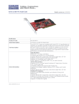
2.3 - Board Parts, Jumpers and Connectors
DDRII B4
DDRII A4
DDRII A3
DDRII B2
DDRII A2
DDRII B1
DDRII A1
CPU1
CPU2
MCH
E7520
CPU2
ICH
6300ESB
J2
J1
J4
PW1
PW2
PCIE
PCIE
PCI 33
PCI 33
PCI X
PCI X
J19
LPC1
J15
FDD1J3
J23
J21
J18
IDE1
BIOS
J13
CF1
J20
J22
J16
J14
LAN1
J5
LPT1
J17
CCMOS1
VGA1
DDRII B3
J24
J25
JP1
This diagram is representative of the latest board revision available at the time of
publishing. The board you receive may not look exactly like the above diagram.

11
Jumper Legend
OPEN - Jumper OFF, without jumper cover
CLOSED – Jumper ON, with jumper cover
Jumper/Connector Function
J1 COM1 Connector
J2 Keyboard & Mouse Connectors
J3 IPMB Connector
J4 LAN Connectors
J5/J14/J18 Chassis Fan Connector
J13 Tyan TARO Connector
J15 COM2 Connector
J16/J22 CPU Fan Connector
J17 Front Panel 1 Header
J19 Front Panel 2 Header
J20 USB 2.0 Connector
J21 SATA1 Connector
J23 SATA2 Connector
J24 LCM Pin Header
J25
IDE1 20
th
Pin 5V Enable/Disable Jumper
(for DOM)
JP1 Enable/Disable ACPI LED Jumer
CCMOS1 Clear CMOS Jumper
CF1 CF Card Connector

12
J24: LCM Module Header
1
2
5
6
Use this header to connect the LCM module with
system monitoring function. This header is reserved for
barebone use.
Signal Pin Pin Signal
VCC
12
COM2_SIN
_34
GND
5VDUAL
56
COM2_SOUT
J15J3
CCMOS1
J24
J25

13
CCMOS1: Clear CMOS Jumper
3
1
Normal
(Default)
3
1
Clear
Use this jumper when you forgot your system/setup
password or need to clear system BIOS setting.
How to clear the CMOS data
- Power off system and disconnect power
supply from AC source
- Use jumper cap to close Pin_2 and 3 for
several seconds to Clear CMOS
- Replace jumper cap to close Pin_1 and 2
Reconnect power supply to AC source
Power on system
J3: IPMB Connector
1
Pin 1 IPMB
DATA
Pin 2 GND
Pin 3 IPMB
CLK
Pin 4 NC
J15: COM2 Connector
1
9
2 10
Signal Pin Pin Signal
DCD
12
DSR
RXD
34
RTS
TXD
56
CTS
DTR
78
R1
GND
910
Key
Use these headers to connect to the COM
devices via the enclosed COM cable.
J25: IDE1 20
th
Pin 5V Enable/Disable Jumper (for DOM)
1
Disable
3
1
Enable
Use this jumper to enable/disable the internal DOM power for
IDE1 20
th
pin.
Pin 1 NC Pin 2 DOM_PWR_SEL
Pin 3 VCC5

14
J20: USB2.0 Connector
1
9
2 1
0
Signal Pin Pin Signal
VCC
12
VCC
P0-
34
P1-
P0+
56
P1+
GND
78
GND
Key
910
NC
Use these headers to connect to the USB devices
via the enclosed USB cable.
J17 J19
J20
JP1

15
J17: Front Panel 1 Header
The Front Panel Header is used to connect some control or signal wires from
motherboard to chassis, such as HDD LED, power LED, power button, and
reset button.
J19: Front Panel 2 Header
1 11
2 12
Signal Pin Pin Signal
LAN1_LED+
12
LAN1_LED-
LAN2_LED+
34
LAN2_LED-
LAN3_LED+
56
LAN3_LED-
ID_LED_PW
78
GND
ID_SWITCH
910
GND
NC
11 12
Key
The front panel 2 header is used to connect
LAN1/2/3 and ID LEDs.
JP1: Enable/Disable ACPI LED Jumper
1
Disable the ACPI LED function. (Default)
Pin 1: 5V-Dual, Pin 2: LED+
1
Enable the ACPI LED function.
Pin 1: 5V-Dual, Pin 2: LED+
HDDLED+
1 2
PWR LED+
HDDLED-
3 4
PWR LED-
GND
5 6
PWR SW+
Reset SW+
7 8
PANSWIN
VCC3
9 10
WLED+
NMI
11 12
WLED-
Standby +5V
13 14
key
SMBus Data
15 16
GND
SMBus Clock
17 18
Chassis Intr# (Active Low)

16
J16
J14
J5
J22
J18
J21 J23

17
J14 (FAN1): Chassis Fan Connector
PWR
GND
Senso
r
Use this header to connect the chassis cooling
fan to your motherboard to keep the system at
optimum performance levels.
J5 (FAN2)/J18(FAN3): Chassis Fan Connectors
PWR
GND
Sensor
Use this header to connect the chassis cooling
fan to your motherboard to keep the system at
optimum performance levels.
J16 (CPU_FAN1)/J22 (CPU_FAN2): CPU_FAN Connectors
PWR
GND
Senso
r
Use this header to connect the processor cooling fan to
your motherboard to keep the system stable and
reliable.
J21 (SATA1)/J23 (SATA2): Serial ATA RAID Connectors
7GND
6RXP
5RXN
4GND
3TXN
2TXP
7
1
1GND
Connects to the Serial ATA ready drives via the
Serial ATA cable
You may use these two Serial ATA ports to
have the support of RAID 0 and 1 through the
on board Intel 6300 ESB chipset.

18
2.4 - Tips on Installing Motherboard in Chassis
Before installing your motherboard, make sure your chassis has the
necessary motherboard support studs installed. These studs are usually
metal and are gold in color. Usually, the chassis manufacturer will pre-install
the support studs. If you are unsure of stud placement, simply lay the
motherboard inside the chassis and align the screw holes of the
motherboard to the studs inside the case. If there are any studs missing,
you will know right away since the motherboard will not be able to be
securely installed.
Some chassis’ include plastic studs instead of metal. Although the plastic
studs are usable, TYAN recommends using metal studs with screws that will
fasten the motherboard more securely in place.
Below is a chart detailing what the most common motherboard studs look
like and how they should be installed.

19
2.5 - Installing the Processor, Heatsink & Fan
Your Tiger i7520SD S5365 supports the latest processor technologies from Intel.
Check the TYAN website for latest processor support:
http://www.tyan.com
CPU & Heatsink Installation
The processor should be installed carefully. Make sure you are wearing an
antistatic strap and handle the processor as little as possible.
Follow these instructions to install your processor
1. Place the CPU in the socket ensuring that the edge of golden arrow is
aligned with the breach edge of CPU socket.
WARNING:
This new processor socket
designed by Intel is easy to be
damaged. The processor has
to be installed very carefully to
prevent the contact pins of the
socket from breaking. It is
strongly recommended the
processor installation job to be
handled by the experienced
technician.
2. Use a flat screw driver to lock the CPU after installation. Refer to the
picture below for the direction of locking and unlocking.

20
3. Install the retention module into the CPU socket from the reverse of
motherboard. Tear off the stick on the retention module before
installing.
4. Place the heatsink on the CPU. Use a screw driver to fix the installation of
heatsink.
/