Eaton CBC-8000 Installation And Operation Instruction Manual

Type
Installation And Operation Instruction Manual

This manual is also suitable for

COOPER POWER
SERIES
MN916001EN
Effective October 2018
Supersedes October 2016
Energy Automation Solutions
MN916001EN
CBC-8000 capacitor bank control installation and operation
instructions
Effective October 2018
New Information
Disclaimer of warranties and limitation of liability
The information, recommendations, descriptions and safety notations in this document are based on Eaton
Corporation’s (“Eaton”) experience and judgment and may not cover all contingencies. If further information is
required, an Eaton sales office should be consulted. Sale of the product shown in this literature is subject to the
terms and conditions outlined in appropriate Eaton selling policies or other contractual agreement between
Eaton and the purchaser.
THERE ARE NO UNDERSTANDINGS, AGREEMENTS, WARRANTIES, EXPRESSED OR IMPLIED, INCLUDING
WARRANTIES OF FITNESS FOR A PARTICULAR PURPOSE OR MERCHANTABILITY, OTHER THAN THOSE
SPECIFICALLY SET OUT IN ANY EXISTING CONTRACT BETWEEN THE PARTIES. ANY SUCH CONTRACT
STATES THE ENTIRE OBLIGATION OF EATON. THE CONTENTS OF THIS DOCUMENT SHALL NOT BECOME
PART OF OR MODIFY ANY CONTRACT BETWEEN THE PARTIES.
In no event will Eaton be responsible to the purchaser or user in contract, in tort (including negligence), strict
liability or otherwise for any special, indirect, incidental or consequential damage or loss whatsoever, including
but not limited to damage or loss of use of equipment, plant or power system, cost of capital, loss of power,
additional expenses in the use of existing power facilities, or claims against the purchaser or user by its
customers resulting from the use of the information, recommendations and descriptions contained herein. The
information contained in this manual is subject to change without notice.
Cover Photo: CBC-8000 capacitor bank control
CBC-8000 capacitor bank control installation and operation instructions MN916001EN—October 2018 Eaton.com/cooperpowerseries i
PRODUCT INFORMATION
Introduction . . . . . . . . . . . . . . . . . . . . . . . . . . . . . . . . . . . . . . . . . . . . . . . . . . . . 1
Read this manual first . . . . . . . . . . . . . . . . . . . . . . . . . . . . . . . . . . . . . . . . 1
Additional information . . . . . . . . . . . . . . . . . . . . . . . . . . . . . . . . . . . . . . . 1
Compliance standards . . . . . . . . . . . . . . . . . . . . . . . . . . . . . . . . . . . . . . . . . . . . 1
Acceptance and initial inspection . . . . . . . . . . . . . . . . . . . . . . . . . . . . . . . . . . . . 1
Handling and storage . . . . . . . . . . . . . . . . . . . . . . . . . . . . . . . . . . . . . . . . . . . . . 1
Control specifications . . . . . . . . . . . . . . . . . . . . . . . . . . . . . . . . . . . . . . . . . . . . . 1
CBC-8000 CAPACITOR BANK CONTROL DESCRIPTION
Description . . . . . . . . . . . . . . . . . . . . . . . . . . . . . . . . . . . . . . . . . . . . . . . . . . . . . 2
Serial number and date code location . . . . . . . . . . . . . . . . . . . . . . . . . . . . . . . . 2
Enclosure features . . . . . . . . . . . . . . . . . . . . . . . . . . . . . . . . . . . . . . . . . . . . . . . 2
Door sensor . . . . . . . . . . . . . . . . . . . . . . . . . . . . . . . . . . . . . . . . . . . . . . . 2
Door latch . . . . . . . . . . . . . . . . . . . . . . . . . . . . . . . . . . . . . . . . . . . . . . . . . 3
Door hold . . . . . . . . . . . . . . . . . . . . . . . . . . . . . . . . . . . . . . . . . . . . . . . . . 3
Jaws meter base . . . . . . . . . . . . . . . . . . . . . . . . . . . . . . . . . . . . . . . . . . . 3
Ground lug . . . . . . . . . . . . . . . . . . . . . . . . . . . . . . . . . . . . . . . . . . . . . . . . 3
Cable security sleeve . . . . . . . . . . . . . . . . . . . . . . . . . . . . . . . . . . . . . . . . 3
Front panel . . . . . . . . . . . . . . . . . . . . . . . . . . . . . . . . . . . . . . . . . . . . . . . . . . . . . 3
Programming panel . . . . . . . . . . . . . . . . . . . . . . . . . . . . . . . . . . . . . . . . . 4
Operating Panel . . . . . . . . . . . . . . . . . . . . . . . . . . . . . . . . . . . . . . . . . . . . 6
Control features . . . . . . . . . . . . . . . . . . . . . . . . . . . . . . . . . . . . . . . . . . . . . . . . . 8
Control security . . . . . . . . . . . . . . . . . . . . . . . . . . . . . . . . . . . . . . . . . . . . 8
Manual mode . . . . . . . . . . . . . . . . . . . . . . . . . . . . . . . . . . . . . . . . . . . . . . 8
Remote mode . . . . . . . . . . . . . . . . . . . . . . . . . . . . . . . . . . . . . . . . . . . . . 8
Automatic mode . . . . . . . . . . . . . . . . . . . . . . . . . . . . . . . . . . . . . . . . . . . . 9
Alarming . . . . . . . . . . . . . . . . . . . . . . . . . . . . . . . . . . . . . . . . . . . . . . . . . . 13
Priority table control . . . . . . . . . . . . . . . . . . . . . . . . . . . . . . . . . . . . . . . . . 13
Metering . . . . . . . . . . . . . . . . . . . . . . . . . . . . . . . . . . . . . . . . . . . . . . . . . . 14
Data logs . . . . . . . . . . . . . . . . . . . . . . . . . . . . . . . . . . . . . . . . . . . . . . . . . 14
Communications . . . . . . . . . . . . . . . . . . . . . . . . . . . . . . . . . . . . . . . . . . . . . . . . 14
Communication ports . . . . . . . . . . . . . . . . . . . . . . . . . . . . . . . . . . . . . . . . 14
Serial SelectComm module . . . . . . . . . . . . . . . . . . . . . . . . . . . . . . . . . . . 14
Ethernet SelectComm module . . . . . . . . . . . . . . . . . . . . . . . . . . . . . . . . . 15
Radio modems . . . . . . . . . . . . . . . . . . . . . . . . . . . . . . . . . . . . . . . . . . . . . 17
INSTALLATION PROCEDURE
Initial programming prior to installation . . . . . . . . . . . . . . . . . . . . . . . . . . . . . . . 18
Mounting the control . . . . . . . . . . . . . . . . . . . . . . . . . . . . . . . . . . . . . . . . . . . . . 18
Power transformer recommendation . . . . . . . . . . . . . . . . . . . . . . . . . . . . . . . . . 19
Installing the control . . . . . . . . . . . . . . . . . . . . . . . . . . . . . . . . . . . . . . . . . . . . . . 20
DIN connector options . . . . . . . . . . . . . . . . . . . . . . . . . . . . . . . . . . . . . . . 22
Wiring harness options . . . . . . . . . . . . . . . . . . . . . . . . . . . . . . . . . . . . . . . 24
Socket mount installation . . . . . . . . . . . . . . . . . . . . . . . . . . . . . . . . . . . . . 25
Pole mount installation . . . . . . . . . . . . . . . . . . . . . . . . . . . . . . . . . . . . . . . 26
Panel mount installation . . . . . . . . . . . . . . . . . . . . . . . . . . . . . . . . . . . . . . 27
Installing the cable security sleeve . . . . . . . . . . . . . . . . . . . . . . . . . . . . . . . . . . 29
Storm trapper installation . . . . . . . . . . . . . . . . . . . . . . . . . . . . . . . . . . . . . 30
Eaton’s Cooper Power series junction box installation . . . . . . . . . . . . . . . 31
SelectComm module installation . . . . . . . . . . . . . . . . . . . . . . . . . . . . . . . 34
Contents
ii CBC-8000 capacitor bank control installation and operation instructions MN916001EN—October 2018 Eaton.com/cooperpowerseries
Radio modem installation . . . . . . . . . . . . . . . . . . . . . . . . . . . . . . . . . . . . . 35
Before placing the control into service . . . . . . . . . . . . . . . . . . . . . . . . . . . . . . . 37
TESTING
Testing an installed control . . . . . . . . . . . . . . . . . . . . . . . . . . . . . . . . . . . . . . . . 38
Removing the control from service . . . . . . . . . . . . . . . . . . . . . . . . . . . . . . . . . . 38
Removing a socket mount control from service . . . . . . . . . . . . . . . . . . . 38
Removing a pole mount control from service . . . . . . . . . . . . . . . . . . . . . 39
Removing a panel mount control from service . . . . . . . . . . . . . . . . . . . . 39
APPROVED SENSOR MANUFACTURERS
Line post sensor . . . . . . . . . . . . . . . . . . . . . . . . . . . . . . . . . . . . . . . . . . . . . . . . 40
Neutral current sensor . . . . . . . . . . . . . . . . . . . . . . . . . . . . . . . . . . . . . . . . . . . . 40
ADDITIONAL INFORMATION
Replacement kits . . . . . . . . . . . . . . . . . . . . . . . . . . . . . . . . . . . . . . . . . . . . . . . . 41
Factory-authorized service centers . . . . . . . . . . . . . . . . . . . . . . . . . . . . . . . . . . 41
CBC-8000 capacitor bank control installation and operation instructions MN916001EN—October 2018 Eaton.com/cooperpowerseries iii
iv CBC-8000 capacitor bank control installation and operation instructions MN916001EN—October 2018 Eaton.com/cooperpowerseries
Product information
CBC-8000 capacitor bank control installation and operation instructions MN916001EN—October 2018 Eaton.com 1
Product information
Introduction
This document provides installation and operation
instructions for the CBC-8000 capacitor bank control.
Refer to the following documents for additional information:
CBC-8000 capacitor bank control ProView NXG application
software programming guide (MN916002EN)
CBC-8000 capacitor bank control communications user
guide (MN916003EN)
Communications Point Data Base (TD916002EN)
CBC-8000 control ordering guide (CA916001EN)
CBC-8000 control reference guide (B1160-11041)
Read this manual first
Read and understand the contents of this manual and follow
all locally approved procedures and safety practices before
installing or operating this equipment.
Additional information
These instructions cannot cover all details or variations in the
equipment, procedures, or processes described, nor provide
directions for meeting every possible contingency during
installation, operation, or maintenance. When additional
information is needed to satisfy a problem not covered
sufficiently for the user's purpose, contact your local Eaton’s
Cooper Power
®
series customer service representative.
Compliance standards
The CBC-8000 control is designed and tested in accordance
with applicable sections of the following standards:
IEC 61000-4-2 Electrostatic discharge
IEC 61000-4-4 Electrical fast transient
IEC 61000-4-5 Combination surge
IEC 61000-4-11 Dip and interrupts
IEC 61000-4-12 Ring/oscillatory wave
IEC 61000-2-27 Mechanical shock
FCC 15 Part B
The CBC-8000 control enclosure is rated NEMA 4X rain-tight
when it is mounted vertically and the door latch is tightened
down to compress the door’s neoprene rubber gasket.
Acceptance and initial inspection
Each CBC-8000 control is completely assembled, tested and
inspected at the factory. It is carefully calibrated, adjusted
and in good condition when accepted by the carrier for
shipment.
Upon receipt, inspect the carton for signs of damage. Unpack
the control and inspect it thoroughly for damage incurred
during shipment. If damage is discovered, file a claim with
the carrier immediately.
Handling and storage
Be careful during handling and storage of the CBC-8000
control to minimize the possibility of damage. If the control is
to be stored for any length of time prior to installation,
provide a clean, dry storage area.
Note: There are several wiring configurations available for
the CBC-8000 control. Apply AC power to the control
as defined by your order number. Refer to Installing
the control on Page 20 in this manual.
Control specifications
The CBC-8000 control specifications are listed below.
Table 1. CBC-8000 control specifications
Spec Value
Temperature range -40° F to 185° F (-40° C to 85° C)
Relative humidity 5% to 95% non-condensing
Power requirements 85 to 265 VAC; 50 Hz or 60 Hz
Maximum wattage CBC-8000 control – 1 RS-232 SelectComm module:
2.5 W @ 120 VAC
3.1 W @ 240 VAC
CBC-8000 control – 1 Power Over Ethernet SelectComm
module:
3.1 W @ 120 VAC
3.7 W @ 240 VAC
Outputs Type 1 Form C contacts interlocked and wired as two
Form A outputs
Inputs Seven sensor inputs for control or monitoring;
0 - 10 VAC
Protocol DNP3 Level 2
Communications Two-Way SelectComm module:
RS-232 serial port
Ethernet port
Wi-Fi port
Size 12.21” W x 13.93” H x 7.5” D
(31 cm W x 35.38 cm H x 19.05 cm D)
Weight 9 lbs (4.08 kg) without mounting hardware
Enclosure Meets or exceeds UL 746C ultraviolet light exposure
and water resistance testing
Fuse rating Eaton fuse style FNM-10 (10 A)
CBC-8000 capacitor bank control description
2 CBC-8000 capacitor bank control installation and operation instructions MN916001EN—October 2018 Eaton.com
CBC-8000 capacitor bank control description
Description
The CBC-8000 control includes extensive system control
functionality, including time, temperature, current, voltage,
var and sensor control operational strategies. Other standard
features include, manual, automatic and remote modes,
safety delay timers, control security and neutral current
sensing with lockout.
The CBC-8000 control is designed for use with switched
distribution feeder capacitor racks and pad mount capacitors.
The metering functions of the control include instantaneous
current on a per-phase basis, instantaneous voltage and
power factor on a per-phase basis, and power (real, reactive,
apparent) on a per phase or total basis. The CBC-8000 control
also monitors Total Harmonic Distortion (THD) and odd
harmonics for voltage and current from the 3rd to the 13th
harmonic.
The front panel LCD display is used to configure the
operating settings for the control. It is also used to display
alarms, counter information, metering, and parameters.
Parameters can also be programmed via a personal
computer connected to the control through the front panel
USB port. Programming, interrogation, and operations are
performed with the ProView NXG software installed on a
computer.
The ProView NXG software includes additional functions
used to display configurable sequence of events, alarms, and
selectable communication points.
The input voltage of the control is auto-ranging from 85 to
265 VAC and it operates on both 50 and 60 Hz systems.
Serial number and date code location
The serial number and date of manufacture for the control is
printed on a label that is attached to the front panel as shown
in
Figure 1. Refer to this date code for any warranty
questions. The date code is shown under the control serial
number and it states the week and year that the control was
manufactured.
Two additional labels are also provided for your use. The
labels are affixed to the inside of the front cover, above the
document holder.
Figure 1. CBC-8000 control serial number and date code.
Enclosure features
CBC-8000 controls manufactured after October 2016
(e.g.,
type 3) include the following additions:
Door sensor
Door latch
•Door hold
Jaws meter base
Ground lug
Cable security sleeve
You can easily identify the type of control that you have by
entering function code 61 on the front panel and scrolling to
the Hardware ID. You can also view the control type with the
ProView NXG software by clicking Help
About ProView
NXG. The control types are as follows:
Ty p e 1 – The control is a legacy control that does not con-
tain the door sensor or the new board with the RTC bat-
tery.
Ty p e 2 – The control contains the new board with the RTC
battery, but it does not contain the door sensor. The con
-
trol contains a new circuit board installed in the old legacy
cabinet.
Ty p e 3 – The control contain the new board with the Real
Time Clock (RTC) battery and the new cabinet with the
door sensor.
Door sensor
A door sensor provides SCADA notification and timestamps
each time the control door is opened and closed. The
physical door contact, wiring and circuitry are all securely
contained inside the enclosure to prevent tampering.
Control
Serial
Number
Control
Date
Code
CBC-8000 capacitor bank control description
CBC-8000 capacitor bank control installation and operation instructions MN916001EN—October 2018 Eaton.com 3
Door latch
The door latches for the CBC-8000 control allow the door to
be secured with 3/8 inch (1.905 cm) ring padlocks. The door
latches will accommodate both the Sterling Security
Systems Junior and Senior series padlocks.
Each enclosure contains two single-loop, latches that are Salt
Fog Test ASTM B117 and NEMA 4X rated.
Door hold
The optional open door hold kit prevents the door swing that
can occur in field maintenance situations. The open door hold
will securely hold the door in a fixed, open position while an
operator is accessing the HMI front panel.
The open door hold kit can be ordered for new controls or it
can be installed as a field retrofit for existing controls.
Figure 2. CBC-8000 control open door hold
Jaws meter base
The distance between the back of the enclosure and the
jaws was increased to provide more room for installing and
securing the meter socket ring. An additional 1/2 inch
(1.27
cm) was added between the back of the pole mount
enclosure and the jaws.
Ground lug
The ground lug for controls manufactured after October 2016
will accommodate a 2 AWG pole ground wire.
Cable security sleeve
An optional cable security sleeve is available to securely
terminate the cabling that enters the bottom of the
enclosure. Adding a cable security sleeve to your control will
help prevent unauthorized personnel from disconnecting the
DIN connector and cable.
The cable security sleeve can be ordered as an option to be
supplied with new controls or it can be installed as a field
retrofit for existing controls.
Note: Security sleeves ordered with new controls are not
installed at the factory. This option must be installed
by the customer.
Figure 3. Cable security sleeve
Front panel
The CBC-8000 control front panel is illustrated in Figure 4 on
page 4.
The front panel is separated into two clearly identified, color-
coded sections:
Programming panel – The top portion of the front panel is
used for programming the control and providing LED
status indication.
Operating panel – The lower portion of the front panel is
used for operating the control and capacitor bank.
The control includes a Power Save feature that will turn off
the backlit LCD display after 5 minutes of inactivity at the
front panel (no buttons pressed). Pressing any button on the
front panel will turn the LCD backlight on.
The control also includes a Reset Menu feature that will
cause the LCD display to revert to the root menu after 5
minutes of inactivity.
CBC-8000 capacitor bank control description
4 CBC-8000 capacitor bank control installation and operation instructions MN916001EN—October 2018 Eaton.com
Figure 4. CBC-8000 control front panel.
Programming panel
The Programming panel contains the following sections:
LCD display and keypad
The LCD display is a 4-line, 20-character display.
Equipment misoperation.
It is possible to improperly configure or customize the CBC-
8000 control with conflicting settings by using either the
front panel HMI or the ProView NXG software.
Improper configuration can result in excessive equipment
operation and eventual damage to the equipment,
The user must ensure that a proper combination is created
and downloaded for the appropriate device application. C1110.0
The keypad functionality is summarized as follows:
•The (Up) arrow button can be used for the following
tasks:
Scroll to the next item up on the current Menu level.
If already at the first item of the current Menu level,
return to the last item of the current Menu.
When editing a selectable option parameter, scroll up to
the next available option.
Change the numerical value from positive to negative or
vice versa.
Change the case of a letter when editing Passwords.
Figure 5. LCD display and keypad functionality.
•The (Down) arrow button can be used to complete the
following tasks:
Scroll to the next item down on the current Menu level.
If scrolled past the last line of the current Menu level,
return to the first line of the current Menu.
When editing a Selectable Option Parameter, scroll
down to the next available option.
Change the numerical value from positive to negative or
vice versa.
Change the case of a letter when editing Passwords.
•The (Left) arrow button is used to go up one Menu level.
•The (Left) arrow button is also used to move left when
editing parameters.
•The (Right) arrow button is used to go down one Menu
level.
•The (Right) arrow button is also used to move right
when editing parameters.
The ESC (Escape) button is used for the following tasks:
Go up one Menu level.
Cancel Edit mode when editing settings without
changing the value.
CBC-8000
MANUAL REMOTE AUTO
TRACKING ALARMS
NEUTRAL
LOCKOUT
RESET
TRIP CLOSE
MODE
AC POWER
CONTROL OK
TRIP
CLOSE
ALARMS
TRACKING
DATA PORT
ESC EDIT
ENTER
123
456
789
FUNC
0
SYM
PQRS XYZTUV
GHI MNOJKL
DEFABC
CBC-8000 capacitor bank control description
CBC-8000 capacitor bank control installation and operation instructions MN916001EN—October 2018 Eaton.com 5
The ENTER button is used for the following tasks:
Go down one Menu level.
Confirm settings change in the Edit mode.
Execute function codes.
Confirm resetting the Resettable Parameters.
Confirm passwords
The EDIT button is used for the following tasks:
Enter the Edit mode to make a change.
The FUNC (Function) button is used to enter the function
code mode. This mode allows you to enter a function code
to go directly to a control option instead of navigating to it
through the use of the front panel. For a list of the function
codes, refer to the CBC-8000 Control Reference (B1160-
11041) document that is shipped with the control.
The ALPHANUMERIC buttons are used for the following
tasks:
Edit scalar parameters.
Enter function codes.
Enter security codes.
Function as shortcuts to Menu items.
The SYM (Symbol) button is used to enter special
characters.
Status Indicator LEDs
The LED indicators, located on the left side of the Operator
panel, display status information for the control and capacitor
bank.
The LEDs have the following meanings:
TRIP – The TRIP LED illuminates to indicate that the
capacitor bank is in the open (tripped) position. A TRIP LED
flashing slowly (approximately 2 seconds per flash),
indicates one of tow possible situations:
the delay timer is running for a pending trip operation
a trip operation has occurred and the reclose delay timer
is running
If the TRIP LED is flashing fast (approximately 1 second
per flash), the trip relay is active and the relay control
timer is running (Bank Operate Time). Timers can be
viewed by entering Function Code 63 on the front
panel, or by selecting Display
Timers in the ProView
NXG software.
CLOSE – The CLOSE LED illuminates to indicate the
capacitor bank is in the closed position. If the CLOSE LED
is flashing slowly, the delay timer is running for a pending
close operation. If the CLOSE LED is flashing fast, the
close relay is active and the control timer is running.
The CLOSE LED will blink when a delayed close is active.
A close will occur when the manual close delay timer
expires.
ALARM – If the ALARM LED is flashing, one or more
alarms are active in the control. Refer to the CBC-8000
capacitor bank control ProView NXG application software
programming guide (MN916002EN) for a complete listing
of alarms.
TRACKING – If the TRACKING LED is flashing, the control
is tracking a condition that may cause automatic control,
such as an overvoltage condition.
Figure 6. Status indicator LEDs (left side).
Power and Diagnostic LEDs
The LED indicators, located on the right side of the Operator
panel, display power and diagnostic information for the
control.
The LEDs have the following meanings:
AC POWER – The AC POWER LED illuminates when the
control detects the presence of AC input power.
CONTROL OK – The CONTROL OK LED illuminates to
indicate that the control passed self-diagnostics and is
capable of normal operation.
Note: A non-illuminated CONTROL OK LED may indicate
that there is a problem with the control.
Figure 7. Power and diagnostic LEDs (right side).
Data port
The Data Port section of the programming panel, shown in
Figure 8 on page 6, provides a USB connection to a
personal computer. This port is used for accessing the
control with the ProView NXG software. All settings,
metering, alarms, and events are available from this port.
CBC-8000 capacitor bank control description
6 CBC-8000 capacitor bank control installation and operation instructions MN916001EN—October 2018 Eaton.com
Figure 8. Data Port
Operating Panel
The Operating panel contains the following buttons:
TRIP Button
The TRIP button, shown in Figure 9, allows an operator to
manually trip the capacitor bank from the front panel. When
the TRIP button is pressed, a control request is sent to the
control. If the control is in Manual mode, the control opens
the capacitor bank.
Explosion hazard.
Move a safe distance away from the capacitor bank after
pressing the TRIP button on the control.
Failure to do so may result in severe personal injury or
death. C1103.0
The TRIP LED can have the following meanings:
IlluminatedWhen the TRIP button is pressed, the LED
illuminates to visually indicate that the button has been
pressed.
Flashing
Slowly
The delay timer is running for a pending trip
operation or a trip operation has occurred and the
reclose delay timer is running. When the LED is flashing
slowly, the LED is lit for 1 second and off for 1 second.
Fast
The trip relay is active and the control timer is
running. When the LED is flashing fast, the LED is lit for
1/2 second and off for 1/2 second.
Off – The TRIP LED is turned off when the capacitor bank
operation timer ends.
Figure 9. TRIP button.
CLOSE button
The CLOSE button, shown in Figure 10, allows an operator to
manually close the capacitor bank from the front panel.
When the CLOSE button is pressed, a control request is sent
to the control. If the control is in Manual mode, the control
closes the capacitor bank.
Explosion hazard.
Move a safe distance away from the capacitor bank after
pressing the CLOSE button on the control.
Failure to do so may result in severe personal injury or
death.
C1104.0
The CLOSE LED can have the following meanings:
Illuminated – When the CLOSE button is pressed, the
LED illuminates to visually indicate that the button has
been pressed.
•Flashing
Slowly
The delay timer is running for a pending
close
operation. When the LED is flashing slowly, the LED is
lit for 1 second and off for 1 second.
Fast
– The close relay is active and the control timer is
running.
When the LED is flashing fast, the LED is lit for
1/2 second and off for 1/2 second.
Off – The CLOSE LED is turned off when the capacitor
bank operation timer ends.
Figure 10. CLOSE button.
One-touch function buttons
These buttons set the operational mode of the control and
they allow quick access to certain menu items.
Illustrated in Figure 11, the one-touch function buttons are
arranged in three rows as follows:
Row 1 – Mode of Operation: Manual, Remote, Auto
Row 2 – Neutral Lockout Reset, Tracking, Alarms
Row 3 – Reserved for future use
CBC-8000 capacitor bank control description
CBC-8000 capacitor bank control installation and operation instructions MN916001EN—October 2018 Eaton.com 7
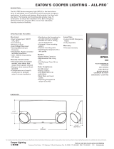
Figure 11. Operating panel one-touch function buttons.
Row 1 – Mode of Operation: Manual, Remote, Auto
Pressing these buttons sets the operational mode of the
control. The control can be placed in only one of the three
operating modes at any given time. The LED in the upper-left
corner of the buttons indicate which mode is currently active.
The auto and remote modes can be set via remote Master
Station communications. Whether the operational mode is
selected manually via the front panel or remotely via SCADA
commands, the LED associated with the current active
operational mode will remain illuminated.
CBCs equipped with two way communications will allow set
point and configuration changes as well as send status and
metering data when in any of the three operational modes.
LEDs located in the upper-left corner of each function button
indicate the status of the function, regardless of manual or
remote activation. For example, if Remote mode is activated
from a SCADA signal, the Remote LED will illuminate even
though it was not activated from the operating panel.
MANUAL – In Manual mode, control of the capacitor bank
can only be initiated by pressing the TRIP or CLOSE
buttons on the operating panel. Pressing the MANUAL
button places the control in manual mode. Once pressed,
the MANUAL LED illuminates to indicate that the control is
in manual operating mode.
This is the highest priority command for the CBC and it
cannot be overridden by any other command to the CBC.
The CBC will not accept any remote trip or close
commands nor will it operate based on local metrics. It
is recommended that the CBC always be placed into
Manual mode when working with the CBC in the field.
Taking the CBC out of Manual mode can only be done
through the front panel. No command from the ProView
NXG software or SCADA can change the operational
mode from Manual.
Note: The control will not accept remote trip and close
commands, or use local metrics to operate the
capacitor bank while in Manual mode.
REMOTE – In Remote mode, the CBC will consider trip
and close commands from the Master Station, local
metrics, or through a local connection with the ProView
NXG software. Remote mode is effectively the same as
Auto mode with the addition of regular priority trip and
close commands from SCADA and the ProView NXG
software. Once pressed, the REMOTE button places the
control in remote mode. The REMOTE LED illuminates to
indicate that the control is in remote operating mode.
AUTO – In Auto mode, control of the capacitor bank is
based only on local metrics such as voltage, vars, sensor
inputs, temperature and time. Once pressed, the AUTO
button places the control in automatic mode. The AUTO
LED illuminates to indicate that the control is in automatic
operating mode.
Note: The control will not accept standard priority remote
commands while in automatic mode; however, the
control will accept high priority SCADA Override Trip
and Close commands while in automatic mode.
SCADA OVERRIDE Mode
The CBC also has a SCADA OVERRIDE mode. SCADA
Override commands are sent only by SCADA to special DNP
points. The CBC will accept SCADA Override operational
commands when in AUTO and REMOTE modes. For safety
reasons, SCADA Override commands are ignored when the
CBC is in MANUAL mode.
SCADA OVERRIDE mode is not REMOTE mode. Entering
Function Code 65 will indicate if SCADA OVERRIDE is active
or inactive. The ProView NXG software cannot send SCADA
OVERRIDE commands. Please refer to Communications
Point Data Base (TD916002EN) for specific DNP point
information.
The CBC uses a Priority Table to resolve conflicts between
operational commands. Please refer to
Priority table
control on Page 13 for additional information.
Row 2 – Neutral Lockout Reset, Tracking, Alarms
NEUTRAL LOCKOUT RESET – If the NEUTRAL
LOCKOUT RESET LED is illuminated, the control has
operated due to the Neutral Current Fault Control Strategy
settings, the control has been locked out. In this condition,
the neutral current lockout must first be reset before the
control will respond to lower priority commands to
operate. Pressing the NEUTRAL LOCKOUT RESET button
takes the control out of the lockout state. The unit can also
be reset remotely by a SCADA command or with the
ProView NXG software.
TRACKING – Pressing the TRACKING button displays the
conditions that are currently being tracked. These
conditions may be scrolled through by using the (Up)
arrow and the (Down) arrow buttons. If the status
indicator TRACKING LED is flashing, the control is tracking
a condition that may cause automatic control, such as an
overvoltage or undervoltage condition. The LED for the
TRACKING button will illuminate when this button is
pressed. Entering Function Code 63 is equivalent to
pressing the TRACKING button.
CBC-8000 capacitor bank control description
8 CBC-8000 capacitor bank control installation and operation instructions MN916001EN—October 2018 Eaton.com
ALARMS – Pressing the ALARMS button displays the
alarms that are currently active. The active alarms may be
scrolled through by using the (Up) arrow and the
(Down) arrow buttons. If the status indicator ALARMS LED
is flashing, one or more alarms are active in the control.
The LED for the ALARMS button will illuminate when this
button is pressed.
Row 3 – Reserved for future use
The buttons in row 3 are not currently used at this time.
Control features
The CBC-8000 capacitor bank control offers the following
standard features:
Control security on Page 8
Manual mode on Page 8
Remote mode on Page 8
Automatic mode on Page 9
Alarming on Page 13
Priority table control on Page 13
Metering on Page 14
Data logs on Page 14
Control security
The control offers customer-programmable security codes to
limit control programming and viewing function access to
authorized personnel. The front panel Human-Machine
Interface (HMI) includes a user-selected security code to
access the settings. Plus, the ProView NXG software has its
own security levels for multiple-user access.
Refer to the CBC-8000 capacitor bank control ProView NXG
application software programming guide (MN916002EN) for
additional information regarding how to set and change
passwords.
Password recovery
If your password is lost, contact your local Eaton’s Cooper
Power series representative.
Manual mode
The Manual operating mode allows manual control of the
capacitor bank using the TRIP and CLOSE buttons on the
front panel. When the control is in Manual mode, remote or
automatic operation of the capacitor bank is disabled.
Note: The MANUAL LED illuminates when the control is in
manual operating mode.
If the MANUAL button is pressed during the delay time of a
remote or automatic control operation, the delay time is
stopped and the pending operation is canceled.
Pressing the MANUAL button places the control in Manual
mode. The control will not accept remote Trip or Close
commands, or use site measurements to operate the
capacitor bank while in Manual mode. This is the highest
priority command for the CBC and it cannot be overridden by
any other command to the CBC.
Taking the CBC out of Manual mode can only be done
through the front panel. No command from the ProView NXG
software or SCADA can change the operational mode from
Manual.
When the control is changed to the Remote or Automatic
operating mode, control based on local conditions is restored
as follows:
For Time control, a 2 minute timer starts when the control
leaves Manual mode and any close or trip operation
requested by the Time control strategy is delayed until the
timer expires. This timer only applies to Time control; it
does not affect capacitor bank operation initiated by any
other control strategy.
For all other Auto control requests, a 30 second manual
delay timer is started when the control is removed from
Manual mode. This is done as a safety measure to prevent
immediate capacitor bank operation in case a track timer is
set to a short time period. If a local condition starts
tracking, before the 30 second manual delay timer has
finished, the remaining amount of time for the manual
delay timer is added to the tracking timer for the local
condition that is requesting the operation. This ensures
that the manual delay timer is allowed to run for the entire
30 second time period and that the track timer is allowed
to run for its entire duration.
Manual close delay time
The manual close delay timer provides a delay from the time
that the manual CLOSE button is pressed to the time that the
manual close operation is performed. This delay gives
service personnel time to move away from the capacitor
bank before the switch actually closes. The CLOSE LED
blinks when the manual close delay timer is active.
The manual close delay is programmable from 30 to 255
seconds in 1 second increments.
Remote mode
The Remote operating mode allows remote operation of the
capacitor bank using a serial or Ethernet SelectComm
communication module or a local USB connection with the
ProView NXG software. Manual operation of the capacitor
bank is disabled when the control is in Remote mode.
However, automatic control is allowed when the control is in
the remote operating mode.
When the control is in Remote mode, commands are
accepted from the Master Station
Note: The REMOTE LED illuminates when the control is in
remote operating mode.
CBC-8000 capacitor bank control description
CBC-8000 capacitor bank control installation and operation instructions MN916001EN—October 2018 Eaton.com 9
If the control is in Manual or Automatic mode and the
REMOTE button is pressed, any trip or close operation that
was initiated when the control was in Manual or Automatic
mode is performed before the control changes to the
Remote operating mode.
Remote SCADA override
Remote SCADA override is a special remote control request,
to trip or close the capacitor bank. It has a control table
priority that is higher than all of the other control table
priorities, except for Manual control.
Automatic mode
The Automatic operating mode allows control of the
capacitor bank, based on local conditions, while preventing
manual or remote control of the capacitor bank except when
the Remote SCADA Override trip or close command is used.
Note: The AUTO LED illuminates when the control is in
automatic operating mode.
If the control is in Manual or Remote mode and the AUTO
button is pressed, any trip or close operation that was
initiated when the control was in Manual or Remote mode is
performed before the control changes to Automatic
operating mode.
The following automatic control operations are supported:
Seasonal control – Seasonal control allows the control to
use a different set of control parameters for two separate
control seasons.
Over Voltage Under Voltage control – Capacitor bank
control is based on the line voltage measurement and
whether or not it is outside of a configurable Over Voltage
Under Voltage (OVUV) threshold for a configurable period
of time.
Emergency voltage control – Capacitor bank control is
based on the line voltage measurement and whether or
not it is outside of a configurable Emergency OVUV
threshold for a configurable period of time.
VAR control – Capacitor bank control is based on the
fundamental kvar measurement and whether or not it is
outside of a configurable threshold for a configurable
period of time.
Time control – Capacitor bank control is based on the
time of day.
Temperature control – Capacitor bank control is based on
the temperature measurement and whether or not it
outside of a configurable threshold for a configurable
period of time.
Sensor Input control – Capacitor bank control is based on
the sensor input value and whether or not it is outside of a
configurable threshold for a configurable period of time.
Current control – Capacitor bank control is based on the
sensor input current value and whether or not it is outside
of the current threshold for a configurable period of time.
Neutral current fault control – Monitors the health of the
capacitor bank by using the fundamental neutral current
measurement to determine if there is a phase imbalance.
A phase imbalance is common when a capacitor’s fuse is
blown or when a capacitor switch has failed. If a fault
condition is detected, the control will not perform any
control operation.
Neutral current verification – Capacitor bank operation is
verified by comparing the fundamental neutral current
measurement to a configurable set point.
Communications loss control – If the control does not
hear from the master station for a configurable period of
time, the control will allow operations to occur based on
local metrics.
Adaptive voltage control – Capacitor bank control is
based on a predictive algorithm that determines whether
or not a capacitor bank operation will cause an OVUV
condition or emergency voltage condition.
If the resulting control action will place the voltage
outside of the OV, UV, or emergency voltage thresholds,
then the CBC rejects the control command.
Seasonal control
The seasonal control feature is used to configure two
separate seasonal time periods for the following control
methods:
Voltage control
VAR control
Time control
Temperature control
When seasonal control is enabled, each control method
within season 1 or season 2 can have a unique set of control
parameters.
Over Voltage Under Voltage control
The Over Voltage Under Voltage (OVUV) control feature
allows control of the capacitor bank if the line voltage
measured by the control is outside of the configurable OVUV
thresholds for a configurable period of time.
The control supports the following OVUV thresholds:
Non-seasonal OVUV thresholds – Used when the
control performs non-seasonal control.
Seasonal OVUV thresholds – Used when the control
performs seasonal control.
Comms Loss OVUV thresholds – Used when the
control loses communications with the master station.
CVR thresholds – Used when the control performs
CVR (Conservation Voltage Reduction) control.
The configurable periods of time that the line voltage must
be outside of a threshold are the OV track time and UV
track time, which are in seconds.
CBC-8000 capacitor bank control description
10 CBC-8000 capacitor bank control installation and operation instructions MN916001EN—October 2018 Eaton.com
If adaptive voltage sensing is also enabled, other automatic
control conditions will only be considered if a control
operation will not cause an OVUV condition.
Emergency voltage control
The emergency voltage control feature allows control of the
capacitor bank if the line voltage measured by the control is
outside of the emergency voltage thresholds for a
configurable period of time.
If adaptive voltage sensing is also enabled, other automatic
control conditions will only be considered if a control
operation will not cause an emergency OVUV condition.
VAR control
The VAR control feature allows control of the capacitor bank
if the fundamental kvar measurement is outside of a
configurable threshold for a configurable period of time.
The configurable thresholds are the trip and close points,
which are in kvar.
The configurable period of time that the kvar value must be
outside of a threshold is the var track time, which is in
seconds.
The control stops tracking kvar measurements if the
capacitor bank is already tripped and the kvar value is below
the trip point or the capacitor bank is already closed and the
kvar value is above the close point.
Time control
The time control feature allows daily control of the capacitor
bank when the local time reaches the On time or Off time.
On time – When the local time reaches the On time, the
control closes the capacitor bank and it remains closed
until the local time reaches the Off time.
Off time – When the local time reaches the Off time, the
control opens the capacitor bank and it remains open until
the local time reaches the On time.
Time control can be used during the week (Monday through
Friday) and on the weekend. In addition, the control supports
the following time control options:
Holidays – User-defined holidays and perpetual holidays,
which are holidays that do not occur on a specific date,
such as Thanksgiving, Memorial Day, and Labor Day.
ON/OFF control – On/Off control with a selectable Off
state. During the On time period, the control will only
operate local controls. During the Off time period, the
control will remain in one of three configurable states: Trip,
Close, or the last known state. Also, during the Off time
period, only manual, SCADA, fault, and emergency
controls will be allowed.
Weekend ON/OFF control – Weekend On/Off control
only applies to Saturday and Sunday. When the local time
reaches the weekend On time, the control closes the
capacitor bank and it remains closed until the local time
reaches the Off time. When the local time reaches the
weekend Off time, the control opens the capacitor bank it
remains open until the local time reaches the On time.
Temperature control
The temperature control feature allows control of the
capacitor bank if the temperature is outside of the
temperature thresholds for a configurable period of time.
The control action that occurs is configurable:
None – Do not perform an operation.
Trip above – Perform a trip operation when the
temperature is above the threshold.
Close above – Perform a close operation when the
temperature is above the threshold.
Trip above close below – Perform a trip operation when
the temperature is above the threshold and perform a
close operation when the temperature is below the
threshold.
Trip below – Perform a trip operation when the
temperature is below the threshold.
Close below – Perform a close operation when the
temperature is below the threshold.
Close above trip below – Perform a close operation when
the temperature is above the threshold and perform a trip
operation when the temperature is below the threshold.
Note: Make sure the actions that are specified for the
minimum and maximum thresholds do not cause
conflicting control operations. For example, the
minimum action cannot be trip above if the maximum
action is close below.
Sensor input control
The sensor input control feature allows control of the
capacitor bank if the sensor input value stays outside of a
configurable threshold for a configurable period of time.
Equipment damage.
The maximum input voltage that can be applied to sensor
inputs in the control is 10 V RMS.
Failure to comply may result in equipment damage. C1105.0
The control action that occurs is configurable:
None – Do not perform an operation.
Trip above – Perform a trip operation when the sensor
input value is above the threshold.
Close above – Perform a close operation when the sensor
input value is above the threshold.
Trip above close below – Perform a trip operation when
the sensor input value is above the threshold and perform
a close operation when the sensor input value is below the
threshold.
Trip below – Perform a trip operation when the sensor
input value is below the threshold.
CBC-8000 capacitor bank control description
CBC-8000 capacitor bank control installation and operation instructions MN916001EN—October 2018 Eaton.com 11
Close below – Perform a close operation when the sensor
input value is below the threshold.
Close above trip below – Perform a close operation when
the sensor input value is above the threshold and perform
a trip operation when the sensor input value is below the
threshold.
Note: Make sure the actions that are specified for the
minimum and maximum thresholds do not cause
conflicting control operations. For example, the
minimum action cannot be trip above if the maximum
action is close below.
Current control – use case for sensor input control
Current control can be accomplished using the sensor input
controls if the site is equipped with current monitoring
sensors.
Figure 12 is a picture of combination voltage and
current sensors installed on all three phases.
As an example, a customer would like to have the capacitor
bank close in above 200
A and open up below 100 A. The
minimum threshold action would be trip below with a value
of 100 and the maximum threshold action would be close
above with a value of 200.
If it is desirable that the capacitor bank remain closed in
between 100
A and 200 A, the minimum threshold action
would be set to close above trip below and the maximum
threshold action would remain at close above.
Figure 12. Capacitor banks with 3-phase line voltage/
current sensors.
Neutral current fault control
Neutral current fault control provides a method to determine
if the capacitor bank is in a fault condition, such as a phase
imbalance. If neutral fault current control is enabled and the
measured fundamental neutral current exceeds the
configurable set point for a configurable period of time, the
following occurs:
The control places the capacitor bank into the opposite
state from the one that caused the fault current.
All control operations, except for manual control and
SCADA override control, are prohibited.
The keypad can still be used to view control settings and
data during a fault condition.
The measured fundamental neutral current, at the time of
the fault, is stored in non-volatile memory. The neutral
current value that caused the fault can then be retrieved at
a later time.
The LED on the NEUTRAL LOCKOUT RESET button will be
illuminated.
Note: A neutral current sensor must be connected to the
control prior to enabling neutral current fault control.
The neutral current lockout can be cleared by pressing the
Neutral Lockout Reset button on the operating panel or by
sending a neutral lockout reset command to the control over
local/remote comms. When the neutral current lockout is
cleared, the fault current value in non-volatile memory is also
cleared and the LED on the NEUTRAL LOCKOUT RESET
button will no longer be illuminated.
Figure 13. Neutral current sensor.
3-Phase Line
Voltage/
Current
Sensors
Capacitor
Banks
CBC-8000 capacitor bank control description
12 CBC-8000 capacitor bank control installation and operation instructions MN916001EN—October 2018 Eaton.com
Figure 14. Neutral current sensor 120 VAC system.
Neutral current verification
The neutral current verification feature provides a method to
verify capacitor bank operation by comparing the RMS
neutral current measurement to a configurable set point.
Note: Neutral current sensing must be enabled to use
neutral current readings to verify capacitor bank
operation. To use neutral current sensing, a neutral
current sensor must be connected to the control prior
to enabling this feature.
The neutral current measurement is expected to be above
the configurable set point for a closed capacitor bank and
below this set point for a tripped capacitor bank.
If the neutral current measurement is not above the set
point for a closed capacitor bank, the control attempts to
close the capacitor bank a configurable number of times
before the operation is considered a failure.
If the neutral current measurement is not below the set
point for an open capacitor bank, the control attempts to
open the capacitor bank a configurable number of times
before the operation is considered a failure.
Note: If neutral current fault control is enabled and the
control is in a fault current condition, the control will
not perform any capacitor bank operation.
Neutral current fault control versus neutral current
verification
Neutral Current Fault Control and Neutral Current Verification
are separate features for monitoring the health of the
capacitor bank and associated equipment. Both features
require a neutral current sensor, although each operates on a
different neutral current measurement according to its
requirements.
Neutral current fault control
Neutral current fault control is the most commonly used
feature. It detects when the capacitors on different phases
become imbalanced due to failed equipment (e.g., a blown
fuse or a stuck switch).
A typical setting for the Fault Control Setpoint is 75% of the
current that flows through one phase. When the filtered
60 Hz neutral current is higher than the specified setpoint,
the control will operate the working phases into the opposite
state to balance the capacitor bank's effect on the line, then
the control will lock in that state and set an alarm indicating
that a neutral current lockout has occurred. Note that neutral
current fault control uses the filtered 60
Hz neutral current to
avoid false positives due to harmonic currents which can
often be high through a capacitor bank, but do not indicate
equipment failure.
Neutral current verification
Neutral current verification operates on the principal that
when the capacitor bank is closed a small amount of neutral
current is expected to be present. Neutral current verification
is intended to provide feedback on whether a capacitor bank
operation appeared successful based on the amount of
neutral current.
When the specified current is not seen on a close operation,
or if the unfiltered RMS neutral current does not go to 0
amps on a trip operation, the operation is retried a specified
number of times. If the operation does not appear to be
successful, an alarm point will be set.
Note that if the line is very balanced, the neutral current
verification feature may not see the current it expects and
therefore may give a false positive. Due to the nature of the
distribution system dynamics, careful planning and review of
the data is necessary to reduce the number of false positives
and make this feature effective. Note that this feature uses
the unfiltered RMS neutral current, which allows the
harmonic current to help determine that the capacitor bank
was successfully closed, which in turn reduces the number
of false positives reported by this feature.
Communications loss control
If the control cannot communicate with the master station
for a configurable period of time, the control enters comms
loss mode.
The following automatic control types may be enabled when
the control enters comms loss mode:
OVUV control
VAR control
Time control
Temperature control
Sensor Input control
Current control
Note: OVUV control uses a secondary set of thresholds
when the control is in comms loss mode.
Note: If a stand-alone control contains a SelectComm
communications module, you must set the port type
to unused; otherwise, the control will go into
Communications Loss operating mode and activate
that alarm. Refer to the CBC-8000 capacitor bank
control communications user guide (MN916003EN)
for this procedure.
CBC-8000 capacitor bank control description
CBC-8000 capacitor bank control installation and operation instructions MN916001EN—October 2018 Eaton.com 13
Adaptive voltage sensing
Adaptive voltage sensing is a predictive algorithm that is
used to determine if a control operation will cause an OVUV
or emergency OVUV voltage condition. The average delta
voltage, which measures the change in voltage due to a
capacitor bank operation, is used along with a 10 second
average of the instantaneous line voltage to see if a control
operation will cause the voltage to be outside of the OVUV
thresholds or emergency voltage thresholds.
If the pending control operation will cause an OVUV or
emergency OVUV voltage condition and it has a priority lower
than OVUV or emergency voltage control, the control
operation is ignored. Any control operation that has a higher
priority than OVUV or emergency OVUV voltage control is
allowed.
Adaptive voltage sensing is used only if OVUV control or
emergency voltage control is enabled.
Note: The average delta voltage is only updated when the
control believes its operation changed the capacitor
bank to the opposite state.
For example, if the capacitor bank is closed and you execute
a close command, or if the capacitor bank is open and you
execute a trip command, the control will not update the
average delta voltage reading since the control did not
change the state of the capacitor bank.
Alarming
Alarming allows the control to set alerts under specific
conditions. The alarming feature is used to indicate when an
event or condition has occurred. The control supports three
types of alarms:
Data – Sets an alarm if a metering value stays outside a
threshold for a configurable period of time. High and low
thresholds may be set for each metering value. Data
alarming is available for the following conditions:
Line voltage: high, low and THD.
3-phase: kvar high and low, kW high and low.
VAR power factor: leading and lagging.
Temperature: high and low.
Sensor
inputs 1 through 6: high and low.
Neutral current: total, fundamental, and THD.
Phases A through C: voltage total high and low, voltage
THD, current total, current THD, leading power factor,
lagging power factor, kW high and low, kvar high and
low.
Status – Sets an alarm if a status value stays active for a
configurable period of time. Status alarms include:
Phases A through C: power flow
VAR power flow
Event – Sets an alarm if a specific event occurs. Event
alarms that can be viewed on the front panel display
include:
Abnormal delta voltage
AC power present
Bad active relay: close or trip
Control request
Controller mode
Ignored control reason
Maximum operations count
Neutral current lockout
Operation failed
Override mode: CVR or SCADA
•Power fail
Relay stuck: closed or tripped
Relay sense failed
Track timer:
sensor
input 1-6, emergency, fault current,
OVUV or var
Information about an alarm can be stored in the Sequence of
Event (SOE) log.
Note: Alarms are not enabled by default and they must be
configured by using the front panel or with the
ProView NXG software.
Priority table control
Priority table control is used to determine if one control
method can override another control method when more
than one control method is enabled. The following table lists
the default priority level for each control method and if that
control method’s priority is configurable.
Note: The lower the number, the higher the priority.
If more than one control method has been configured with
the same priority, the default priority level is used to
determine which control method has the highest priority.
Table 2. Priority control levels.
Default Priority
Level
Control Method Priority Level
Configurable?
0 Manual Control No
1 SCADA Override Yes
2 Fault Current Control Yes
3 Emergency OVUV Yes
4 Time Control (when set to On/Off) Yes
5 OVUV Control Yes
6 VAR Control Yes
7 Phase A Secondary Voltage Yes
8 Phase B Secondary Voltage Yes
CBC-8000 capacitor bank control description
14 CBC-8000 capacitor bank control installation and operation instructions MN916001EN—October 2018 Eaton.com
Metering
Note: The optional sensor input hardware is required to
perform 3-phase metering. Refer to the following
sections for more information on the connectors that
are used for 3-phase metering:
14-Pin DIN connector
(3-phase metering/control) on Page 23 and 8-Pin
DIN connector (sensor inputs only) on Page 23.
The control can perform the following instantaneous
metering functions:
Real, reactive, and apparent power for each phase and
total, including power direction, on a per-phase basis.
Instantaneous voltage and currents on a per phase basis
(including odd harmonics up to the 13th).
Voltage and current Total Harmonic Distortion (THD) for
each phase.
Voltage-current phase difference on each phase.
Capacitor bank neutral current, THD, total, fundamental,
and harmonics up to the 13th.
Sensor input readings.
Phase angle difference.
Note: The control can also perform 3-phase control by
establishing thresholds for the sensor inputs.
Data logs
The control stores two types of data logs:
Sequence of Events log – Logs event information.
Profile log – Logs interval information.
Refer to the CBC-8000 capacitor bank control ProView NXG
application software programming guide (MN916002EN) for
additional information.
Communications
Remote operation of the control requires the use of a
communication port and a SelectComm communication
module. The SelectComm modules are plug and play. Once
the SelectComm module is installed the firmware will
automatically detect the module and configure the control for
the hardware change.
Communication ports
The CBC-8000 control has two communication ports. The
first communication port, which is located above the second
port, supports serial and Ethernet SelectComm
communication modules.
The following SelectComm communication options are
available when the control is ordered:
No SelectComm modules
One Serial SelectComm module
One Ethernet SelectComm module
The second communication port, which is located below the
first port, will support future options.
In addition, the CBC-8000 control has a front panel USB data
port, which is used by the ProView NXG software to
communicate with the control. For more information about
the front panel USB data port, refer to the Operating Panel
section of this manual.
Serial SelectComm module
The Serial SelectComm module enables the control to
communicate over an RS-232 serial connection using the
DNP3 protocol. An example of the Serial SelectComm
module is shown in
Figure 15.
Note: The power to the control must be off when installing
or removing SelectComm Modules.
The Serial SelectComm module includes the following
connectors:
DB9 serial connector
13.7 VDC radio power connector
The power capacity of the radio power connection is
13.7
VDC continuous; however, the current output by the
power supply is different depending on when the control
was manufactured as explained in the following notice.
CBC-8000 controls manufactured from June 2012 until
December 2016 have a 13.7 VDC, 1.7 A continuous power
supply.
CBC-8000 controls manufactured in January 2017 with a
serial number of 800015767, or higher, have a 13.7 VDC, 3 A
continuous power supply.
9 Phase C Secondary Voltage Yes
10 Phase A Current Yes
11 Phase B Current Yes
12 Phase C Current Yes
13 Temperature Control Yes
14 Remote Control No
15 Time Control (when in Normal state) No
16 None No
Table 2. Priority control levels. (continued)
  • Page 1 1
  • Page 2 2
  • Page 3 3
  • Page 4 4
  • Page 5 5
  • Page 6 6
  • Page 7 7
  • Page 8 8
  • Page 9 9
  • Page 10 10
  • Page 11 11
  • Page 12 12
  • Page 13 13
  • Page 14 14
  • Page 15 15
  • Page 16 16
  • Page 17 17
  • Page 18 18
  • Page 19 19
  • Page 20 20
  • Page 21 21
  • Page 22 22
  • Page 23 23
  • Page 24 24
  • Page 25 25
  • Page 26 26
  • Page 27 27
  • Page 28 28
  • Page 29 29
  • Page 30 30
  • Page 31 31
  • Page 32 32
  • Page 33 33
  • Page 34 34
  • Page 35 35
  • Page 36 36
  • Page 37 37
  • Page 38 38
  • Page 39 39
  • Page 40 40
  • Page 41 41
  • Page 42 42
  • Page 43 43
  • Page 44 44
  • Page 45 45
  • Page 46 46
  • Page 47 47
  • Page 48 48
  • Page 49 49
  • Page 50 50

Eaton CBC-8000 Installation And Operation Instruction Manual

Type
Installation And Operation Instruction Manual
This manual is also suitable for

Ask a question and I''ll find the answer in the document

Finding information in a document is now easier with AI