EtherFast
®
II Series
10/100 Managed
24-Port GigaSwitch
Use this guide to install:
Linksys EtherFast
®
II 10/100
Managed 24-Port GigaSwitch
(EG24M)
User Guide

COPYRIGHT & TRADEMARKS
Copyright © 2000 Linksys, All Rights Reserved. EtherFast is a registered trademark of
Linksys. Microsoft, Windows, and the Windows logo are registered trademarks of
Microsoft Corporation. All other trademarks and brand names are the property of their
respective proprietors.
LIMITED WARRANTY
Linksys guarantees that every 10/100 Managed 24-Port GigaSwitch is free from physi-
cal defects in material and workmanship under normal use for FIVE years from the date
of purchase. If the product proves defective during this warranty period, call Linksys
Customer Support in order to obtain a Return Authorization Number. BE SURE TO
HAVE YOUR PROOF OF PURCHASE ON HAND WHEN CALLING. RETURN
REQUESTS CANNOT BE PROCESSED WITHOUT PROOF OF PURCHASE. When
returning a product, mark the Return Authorization Number clearly on the outside of the
package and include your original proof of purchase. All customers outside of the
United States of America and Canada shall be held responsible for shipping and han-
dling charges.
IN NO EVENT SHALL LINKSYS’ LIABILITY EXCEED THE PRICE PAID FOR THE PROD-
UCT FROM DIRECT, INDIRECT, SPECIAL, INCIDENTAL, OR CONSEQUENTIAL DAM-
AGES RESULTING FROM THE USE OF THE PRODUCT, ITS ACCOMPANYING SOFT-
WARE, OR ITS DOCUMENTATION. LINKSYS DOES NOT ISSUE REFUNDS. WARRAN-
TY DOES NOT COVER NATURAL DISASTERS OR ACTS OF NATURE.
Linksys makes no warranty or representation, expressed, implied, or statutory, with
respect to its products or the contents or use of this documentation and all accompa-
nying software, and specifically disclaims its quality, performance, merchantability, or
fitness for any particular purpose. Linksys reserves the right to revise or update its
products, software, or documentation without obligation to notify any individual or entity.
Please direct all inquiries to:
Linksys P.O. Box 18558, Irvine, CA 92623.
FCC STATEMENT
The 10/100 Managed 24-Port GigaSwitch has been tested and found to comply with
the limits for a Class A digital device, pursuant to Part 15 of the FCC Rules. These lim-
its are designed to provide reasonable protection against harmful interference in a resi-
dential installation. This equipment generates, uses, and can radiate radio frequency
energy and, if not installed and used according to the instructions, may cause harmful
interference to radio communications. However, there is no guarantee that interference
will not occur in a particular installation. If this equipment does cause harmful interfer-
ence to radio or television reception, which is found by turning the equipment off and
on, the user is encouraged to try to correct the interference by one or more of the fol-
lowing measures:
• Reorient or relocate the receiving antenna
• Increase the separation between the equipment or device
• Connect the equipment to an outlet other than the receiver’s
• Consult a dealer or an experienced radio/TV technician for assistance
008

Linksys EtherFast
®
II Series
Table of Contents
Introduction 1
Package Contents 2
Getting to Know the GigaSwitch 3
LEDs 3
The RJ-45 Ports 4
The Gigabit Expansion Ports 4
The Console Port 4
Installing the GigaSwitch 5
Pre-Installation Considerations 5
Rack-Mounting the GigaSwitch 6
Powering on and Resetting the GigaSwitch 7
Uplinking the GigaSwitch 7
Installing the Gigabit Expansion Modules 7
Switch Management 8
Overview 8
Local Console Management 8
Remote Console Management 9
SNMP Management 9
Assigning an IP Address to the GigaSwitch 9
Configuring the GigaSwitch 10
Overview 10
Web-Based Configuration and Management 10
Logging On to the GigaSwitch 10
Basic Management Activities 11
General Management Configuration 12
Changing the System Name 12
Changing the Location 13
Changing the Administration Password 13
Changing the Guest Password 15
Statistic Collection 15
Reboot-on-Error 16
Remote Telnet Login 16
Returning to the Basic Management Screen 17
10/100 Managed 24-Port GigaSwitch
LAN Port Configuration 17
Changing the Speed and Flow Control 18
Setting the Line Speed 18
Changing the Flow Control 20
Displaying Physical Port Address 20
Returning to the Basic Management Screen 21
Console Port Configuration 21
Changing the Console Baud Rate 22
Selecting a Flow Control Method 22
Enabling or Disabling Modem Control Options 23
Specifying a Modem Setup String 23
Enabling or Disabling SLIP 24
Specifying a SLIP Address 24
Specifying a SLIP Subnet Mask 25
Returning to the Basic Management Screen 25
Advanced Management Activities 26
Switching Database Configuration 27
VLAN Perspective 28
Default VLAN 28
Obtaining a VLAN Perspective 28
Creating a New VLAN 29
Adding New Switch Ports 30
Deleting a VLAN ID 32
Viewing VLAN Activities 33
Searching for MAC Addresses 34
Obtaining Additional Information 34
Scrolling Through Domains 35
Exiting the VLAN Screens 35
Viewing VLAN Settings 35
Adding Ports 36
Deleting Ports 37
IP Multicast Group Perspective 38
MAC Address Perspective 39
Port Perspective 40
Per Port VLAN Activities 40
Scrolling Through MAC Addresses 41
Per Port Statistics 42

10/100 Managed 24-Port GigaSwitch
Introduction
Maximize your network potential with the ultimate high-speed manageable
switch. The EtherFast II 10/100 Managed 24-Port GigaSwitch from Linksys
delivers a combination of Ethernet, Fast Ethernet, and Gigabit Ethernet solu-
tions, all in one surprisingly affordable package.
Perfect for demanding enterprise environments, the GigaSwitch’s “intelligent”
design provides maximum network control, regulating traffic and eliminating
server bottlenecks. The included software, with its web management interface
and upgrade capability, makes the GigaSwitch ideal for interactive web-based
applications.
And if it’s expansion you’re looking for, the 10/100 Managed 24-Port
GigaSwitch’s rack-mountable design and optional fiber expansion modules
ensure that your network will be primed to grow right along with your busi-
ness.
So when you’re ready to bring your network up to speed, bring it up to
Gigabit speed--with the EtherFast II 10/100 Managed 24-Port GigaSwitch.
1
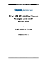
The Linksys EtherFast II
10/100 Managed 24-Port GigaSwitch
Linksys EtherFast
®
II Series
IP Networking 43
IP & RIP Settings 44
ARP Table Settings 45
Adding Static ARP Table Entries 45
Deleting Static ARP Table Entries 47
Searching for ARP Table Entries 47
Routing Table 48
Adding Router Table Entries 49
Deleting Router Table Entries 50
Searching for Router Tsble Entries 51
DHCP Gateway Settings 51
Ping Settings 56
Bridging 57
Static Filtering 58
Spanning Tree Functions 60
Spanning Tree Port Configuration 60
Spanning Tree Port States 62
Spanning Tree Path Costs 63
Spanning Tree Port Priorities 64
SNMP Functions 65
Other Protocols 68
Port Trunking 69
Port Mirroring 71
Upgrading Firmware 73
SNMP and RMON Management 75
Overview 75
SNMP Agent and MIB-2 (RFC 1213) 75
RMON MIB (RFC 1757) and Bridge MIB (RFC 1493) 76
RMON Groups Supported 76
Bridge Group s Supported 77
Appendix 78
About Fast Ethernet 78
About Gigabit Ethernet 79
Fiber Optic Cabling 79
Twisted-Pair Cabling 80
Crimping Your Own Network Cables 81
Specifications 82
Customer Support 83

10/100 Managed 24-Port GigaSwitch
3
Getting to Know the GigaSwitch
MAIN
Power The LED will illuminate when the switch is powered on.
Management The LED will illuminate when management functions are
being performed.
PER PORT
Link 10/100 The LED will illuminate orange when the port is operating
(Row A) at 10Mbps, and illuminate green when operating at 100Mbps.
Tx/Rx The LED will flicker green when the port is transmitting
(Row B) data, and flicker orange when receiving data.
FD/Col The LED will illuminate green when the port is operating
(Row C) in full-duplex mode, and flicker orange when collisions are
being encountered.
GIGABIT
Link The LED will illuminate when the Gigabit Switch Module
is successfully connected to a network.
Tx/Rx The LED will flicker when the Gigabit Switch Module
is transmitting or receiving data.
FD The LED will illuminate when the Gigabit Switch Module
is operating in full-duplex mode.
Linksys EtherFast
®
II Series
• One EtherFast II 10/100 Managed 24-Port GigaSwitch
• One Power Cord
• Mounting Brackets
• One Serial/Console Cable
• User Guide and Registration Card
2
LEDs
Package Contents for the EtherFast II
10/100 Managed 24-Port GigaSwitch

10/100 Managed 24-Port GigaSwitch
Installing the GigaSwitch
Fast Ethernet Considerations
If you will be using the GigaSwitch for Fast Ethernet (100Mbps) applications,
you must observe the following guidelines:
• The maximum UTP cabling length using Category 3 cable is 328 feet (100
meters).
Full-Duplex Considerations
As previously mentioned, the GigaSwitch provides full-duplex support for its
RJ-45 ports. Full-duplex operation allows data to be sent and received simul-
taneously, doubling a port’s potential data throughput.
If you will be using the GigaSwitch in full-duplex mode, the maximum UTP
cable length using Category 5 cable is 328 feet (100meters).
Positioning the GigaSwitch
Before you choose a location for the GigaSwitch, observe the following
guidelines:
• Keep cabling away from sources of electrical noise, power lines, and
fluorescent lighting fixtures.
• Position the GigaSwitch away from water and moisture sources.
• To ensure adequate air flow around the GigaSwitch, be sure to provide a
minimum of one inch (25mm) clearance.
• Do not stack free-standing GigaSwitches more than four units high.
5
Linksys EtherFast
®
II Series
The 10/100 Managed 24-Port GigaSwitch is equipped with twenty-four auto-
sensing RJ-45 ports. These RJ-45 ports support network speeds of either
10Mbps or 100Mbps, and can operate in half- and full-duplex modes. Auto-
sensing technology enables each port to automatically detect the speed of the
device connected to it (10Mbps or 100Mbps), and adjust its speed and duplex
accordingly.
To connect a device to a port, you will need to use a network cable. UTP
Category 3 cable is acceptable for 10BaseT networks, however, if you are
using 100BaseTX devices you will need to use UTP Category 5 (or better)
cable. For more information on twisted-pair cabling, refer to the Twisted-Pair
Cabling section on page 80.
The 10/100 Managed 24-Port GigaSwitch is equipped with two gigabit
expansion ports, providing for the installation of one or two expansion mod-
ules. These ports provide links to high-speed network segments or individual
workstations at speeds of up to 1000Mbps (Gigabit Ethernet).
To establish a Gigabit Ethernet connection, you will need to install a SX or
TX Gigabit expansion module and use fiber optic cabling. for more informa-
tion on fiber optic cabling, refer to the Fiber Optic Cabling section on page
79.
The 10/100 Managed 24-Port GigaSwitch is equipped with a serial port
labeled CONSOLE (located on the rear of the switch) that allows you to con-
nect to a computer (for configuration purposes) using the provided serial cable.
4
The RJ-45 Ports
The Gigabit Expansion Ports
Pre-Installation Considerations
The Console Port

10/100 Managed 24-Port GigaSwitch
To power on the GigaSwitch, simply connect the AC power cord to the back
of the GigaSwitch, then plug the power cord into an electrical outlet. The
GigaSwitch will boot up within approximately 30 seconds.
If you need to reset the GigaSwitch, depress the RESET button (located on
the rear of the switch) for approximately one or two seconds.
Port 24 on the EtherFast II 10/100 Managed 24-Port GigaSwitch can act as an
uplink port, allowing you to uplink to other switches or hubs using a standard
Ethernet connection.
To uplink the switch, connect one end of a Category 5 (or better) network
cable into Port 24, then connect the other end of the cable into the desired
network device’s uplink port. To enable uplinking capability, depress the
MDI/MDIX button on the front of the switch.
Use the following instructions to install the Gigabit Expansion Modules:
Before you begin power off the GigaSwitch by disconnecting all cables from
the GigaSwitch.
1. Place the GigaSwitch right side up, with the rear panel facing you.
2. Use a screwdriver to remove the desired Expansion Module cover plate
(labeled “Slot 1” and “Slot 2”). Set the screws aside for step 4.
3. Insert the Gigabit Expansion Module (must be purchased seperately) into
the selected Gigabit Expansion Port, ensuring that it is seated firmly in
place.
4. Secure the module in place using the screws and a screwdriver.
The Gigabit Expansion Module installation is complete.
You can now re-connect the cables to the back of the GigaSwitch.
7
Linksys EtherFast
®
II Series
The 10/100 Managed 24-Port GigaSwitch can be used as a free-standing unit,
or installed in any standard 19-inch rack.
Use the following instructions to rack-mount the GigaSwitch:
Before you begin, disconnect all cables from the GigaSwitch.
1. Place the GigaSwitch right side up, with the front panel facing you.
2. Position a mounting bracket over the screw holes on one side of the
GigaSwitch.
3. Secure the mounting bracket by inserting three screws into the screw
holes. Use a screwdriver to tighten the screws, ensuring that they are
fastened firmly in place.
4. Repeat steps 2 and 3 to install the other mounting bracket on the opposite
side of the GigaSwitch.
5. Insert the GigaSwitch into the 19-inch rack and secure it with suitable
screws (not provided). Ensure that the ventilation holes are not obstructed.
The rack-mount installation is complete.
You can now re-connect the cables to the back of the GigaSwitch.
6
Rack-Mounting the GigaSwitch Powering On and Resetting the GigaSwitch
Uplinking the GigaSwitch
Installing the Gigabit Expansion Modules

10/100 Managed 24-Port GigaSwitch
Remote Console Management
You can manage the GigaSwitch remotely by having a remote host establish a
Telnet connection to the switch via an Ethernet or modem link.
To use this management method:
• The host must run a SLIP protocol if a modem is used
• The GigaSwitch must have an IP address
The Remote Console Management interface is identical in appearance and
functionality to the Local Console Management interface. If you are using
Microsoft’s Telnet, the terminal setting should be set to VT100/ANSI.
SNMP Management
You can manage the GigaSwitch across a LAN using an SNMP Network
Management Station with a graphical user interface. This management
method allows you to monitor statistical counters and set switch parameters
from the remote Network Management Station.
To use this management method:
• The network must use the IP protocol
• The GigaSwitch must be configured on the network with a proper IP address
Assigning an IP Address to the GigaSwitch
To manage the GigaSwitch remotely through the console port or with an
SNMP Management Station, you must assign an IP address to the
GigaSwitch. To assign an IP address to the GigaSwitch, refer to page 44 in
the Configuring the GigaSwitch section.
Logging On to the GigaSwitch
When you log on to the GigaSwitch for the first time, a sign-in string appears
and you are prompted for a console login name and password. The factory
default login name is set as “admin” and the password is “123456”. If you
desire, you can change this password after you log on.
9
Linksys EtherFast
®
II Series
Switch Management
The Linksys EtherFast II 10/100 24-Port Managed GigaSwitch offers an easy-
to-use, menu-driven console interface. Using this interface, you can perform
various switch configuration and management activities, including:
• Configuring system and port parameters
• Assigning an IP address
• Configuring routing properties
• Configuring ARP
• Configuring DHCP
• Setting VLAN policy
• Setting packet filtration
• Configuring STP and SNMP parameters
• Upgrading software
There are four methods of managing the GigaSwitch:
• Local Console Management using the serial port
• Remote Console Management using a network or dial-up connection
• Using an SNMP Management Station
• Web-Browser
Local Console Management
You can manage the GigaSwitch locally by connecting the switch to a PC or
workstation with terminal emulation software using the serial port.
Before you log on to the GigaSwitch, make sure that the switch’s serial port
settings are as follows:
BAUD RATE: 115200
FLOW: None
PARITY: None
STOP BITS: 1
DATA BITS: 8
EMULATION: ANSI
CURSOR EMULATION: VT100
8
Overview

10/100 Managed 24-Port GigaSwitch
After you log on to the GigaSwitch, the Switch Management screen will
appear.
The Switch Management screen consists of a series of menu boxes. Each
menu box has several options, which are listed vertically. A highlight in each
box lets you select the option you wish to choose; pressing the Enter key
activates the highlighted option.
To navigate through the Console Interface use the Up Arrow or Down Arrow
keys to move up or down, use the Enter key to select, and the Esc key to
return to the previous selection; menu options and any values entered or pres-
ent will get highlighted. Note that the bottom of the window always has a list-
ing of the appropriate key strokes.
Basic management activities consist of General, LAN port, and console port
tasks. To perform basic management activities:
1. From the Switch Management screen, highlight Basic Management and
press Enter. The Basic Management screen will appear.
2. From the Basic Management screen, highlight the desired option and
press the Enter key:
11
Linksys EtherFast
®
II Series
Configuring the GigaSwitch
The Linksys EtherFast II 10/100 24-Port Managed GigaSwitch features a
menu-driven console interface for switch configuration. The GigaSwitch can
be configured locally through the serial port or remotely via a Telnet connec-
tion.
This User Guide provides instructions on how to configure and manage the
GigaSwitch using the console interface. If you wish to manage the switch
through a web connection, you can do so by connecting to the GigaSwitch’s
IP Address using your web browser.
Although the web-based management menu will differ in appearance from
the console-based management menu, you will still have access to all the
same configuration and management features.
When logging on to the GigaSwitch, you will receive the following screen
prompt:
Linksys Gigabit Switch
Screen Name:
System Name
Login:
Enter the default login and password (see page 9), pressing Enter after each
entry (as shown in the image below).
10
Overview
Web-Based Configuration and Management
Logging On to the GigaSwitch
Basic Management Activities

10/100 Managed 24-Port GigaSwitch
2. Enter a system name (16 characters max.). If you make a mistake, use the
Backspace key to delete the error.
3. Press Enter to return to the General screen.
Changing the Location
1. From the General screen, move the cursor to Location and press the Enter
key. The Enter Location screen will appear.
2. Enter a location name. If you make a mistake, use the Backspace key to
delete the error.
3. Press Enter to return to the General screen.
Changing the Administration Password
1. Use the Down Arrow key to highlight admin Password and press the Enter
key. The Enter Old Password screen will appear.
2. Enter the current password. Each character you type appears as an
asterisk (*). If you make a mistake, use the Backspace key to delete the
error.
3. Press Enter. The Enter New Password screen (see next page) will appear.
13
Linksys EtherFast
®
II Series
• General allows you change the system name, location, administration and
guest passwords, statistics collection, reboot-on-error, and remote Telnet
login.
• LAN Port allows you configure speed and flow control, link type, and
physical address.
• Console Port allows you change the console baud rate, flow control
method, modem control, and setup string; enable or disable SLIP; and con-
figure the SLIP address and SLIP subnet mask.
General Management Configuration
Select General from the Basic Management screen. The General screen will
appear, with the cursor on System Name, with any value highlighted.
Use the following procedure to configure the general management options:
Changing the System Name
1. From the General screen, highlight System Name and press the Enter key.
The Enter System Name screen appears.
12

10/100 Managed 24-Port GigaSwitch
Changing the Guest Password
1. Use the Down Arrow key to highlight guest Password and press the Enter
key. The Enter New Password screen will appear.
2. Enter a new guest password. If you make a mistake, use the Backspace
key to delete the error. The password is case-sensitive, can be no
more than 16 characters (only alphanumeric characters and the underscore
“_” character can be used).
3. Press Enter to return to the General screen.
Statistic Collection
1. From the General screen, highlight Statistic Collection and press the Enter
key. The following screen will appear.
2. Highlight one of the following choices:
Disabled (prevents statistic collection to the GigaSwitch)
Enabled (allows statistic collection to the GigaSwitch)
3. Press Enter to return to the General screen.
15
Linksys EtherFast
®
II Series
4. Enter the new password. For security, each password character you
type appears as an asterisk (*). The password is case-sensitive, can be no
more than 16 characters (only alphanumeric characters and the underscore
“_” character can be used).
5. Press Enter. A screen will prompt you to re-enter the new password.
6. Re-enter the new password you typed in step 4 and press Enter. The
Password Changed message will appear, confirming that the new password
is in effect.
7. Press Enter to remove the message and return to the General screen. The
admin password will appear as asterisks in the admin Password field.
14

10/100 Managed 24-Port GigaSwitch
2. Highlight one of the following choices:
Disabled (prevents remote Telnet logins to the GigaSwitch)
Enabled (allows remote Telnet logins to the GigaSwitch. This is the
default setting)
3. Press Enter to return to the General screen.
Returning to the Basic Management Screen
After completing the general management activities, press the Esc key to exit
the General screen and return to the Basic Management screen. You can then
select another option from the Basic Management screen or press Esc to
return to the Switch Management screen.
LAN Port Configuration
Select LAN Port from the Basic Management screen. The LAN Port
Configurations screen will appear, with Speed & Flow Control highlighted.
Use the procedures in this section to configure the LAN Port Configuration
options for one or more ports, including:
• Speed & Flow Control
• Physical Address (this option only appears when System MAC Address in the
General screen is set to Multiple)
17
Linksys EtherFast
®
II Series
Reboot-on-Error
1. From the General screen, highlight Reboot-On-Error and press the Enter
key. The following screen will appear.
2. Highlight one of the following choices:
Disabled (prevents the GigaSwitch from automatically resetting
when a fatal error is detected. This setting is useful when a
persistent problem needs to be reported)
Enabled (allows the GigaSwitch to automatically reset when a fatal
error is detected)
3. Press Enter to return to the General screen.
Remote Telnet Login
1. From the General screen, highlight Remote Telnet Login and press the
Enter key. The following screen will appear.
16

10/100 Managed 24-Port GigaSwitch
2. Highlight the line Speed Option you want to select for the port. Auto allows
the GigaSwitch to automatically determine the line speed and duplex
mode. All the other selections force the GigaSwitch to use a specific line
speed and duplex mode.
3. Press Enter. You will return to the Speed & Flow Cntl Options screen and
the line speed setting you selected appears next to Line Speed.
4. To configure the flow control for this port, proceed to Changing the Flow
Control on page 20 .
5. To configure the line speed for additional ports, press Esc to remove the
Speed & Flow Cntl Options screen. Then highlight the port you want to
configure and repeat steps 1 through 4.
If you want to disable a port, highlight the desired port, then click Enter.
In the Port Settings Options box select Admin Control. Click Enter.
In the Admin Status Options box, select Down. Click Enter.
19
Linksys EtherFast
®
II Series
Changing the Speed and Flow Control
1. From the LAN Port Configurations screen, highlight Speed & Flow
Control and press the Enter key. A screen similar to the following will
show the current line speed settings for all ports. If an expansion module is
installed in the switch, it will also be listed.
2. You can configure each port individually or all ports at one time. To con-
figure an individual port, highlight it and press Enter. To configure all
ports, highlight All Ports (the top option in the previous screen) and press
Enter. If an expansion module is present, choose either All 10/100M Ports
or All 1000M Ports. The Speed & Flow Cntl Options screen will appear
3. Proceed to the appropriate section:
To set the line speed, proceed to the Setting the Line Speed section
To set the flow control, go to Changing the Flow Control on
page 20.
Setting the Line Speed
1. Press Enter with the Line Speed value highlighted . The Speed Options
menu will appear (see screen next page).
18

10/100 Managed 24-Port GigaSwitch
Returning to the Basic Management Screen
After completing the general management activities, press the Esc key to exit
the General screen and return to the Basic Management screen. You can then
select another option from the Basic Management screen or press Esc to
return to the Switch Management screen.
Console Port Configuration
Select Console Port from the Basic Management screen, the Console Port
Configurations screen will appear, with the Baud Rate value highlighted.
Use the procedures in this section to configure the Console Port
Configurations options for one or more settings, including:
• Specifying Baud Rate
• Specifying Flow Control
• Enable or Disable Modem Control
• Enter Modem Setup String
• Enable or Disable SLIP
• Specify a Slip Address
• Specify a SLIP Subnet Mask
21
Linksys EtherFast
®
II Series
6. When you finish, press the Esc key from the Line Speed & Flow Control
screen to return to the LAN Port Configurations screen.
Changing the Flow Control
1. With the Speed & Flow Cntl Options screen displayed, press the Down
Arrow key to highlight Flow Control and press Enter. The Flow Cntl
Options screen will appear.
2. Highlight the desired flow control option for the port. Auto allows the
GigaSwitch to automatically determine whether or not to use flow control.
On enables flow control at all times. Off disables flow control at all times.
3. Press Enter. You will return to the Speed & Flow Cntl Options screen, and
the selected flow control setting will appear next to Flow Control.
4. To configure the flow control for additional ports, press Esc to remove
the Speed & Flow Cntl Options screen. Highlight the desired port then
press Enter. Highlight Speed and Flow Control, then press Enter. Repeat
steps 1 through 3 for each additional port.
5. When you are finished, press the Esc key from the Line Speed & Flow
Control screen to return to the LAN Port Configurations screen.
Displaying Physical Port Address
The following procedure describes how to display the physical port address.
This option only appears on the LAN Port Configurations screen when System
MAC Address in the General screen is set to Multiple. The addresses of each
individual port will be displayed.
1. From the LAN Port Configurations screen, highlight Physical Address and
press the Enter key. A screen similar to the following (see next page) will
appear.
20

10/100 Managed 24-Port GigaSwitch
Enabling or Disabling Modem Control Options
1. From the Console Port Configurations screen, highlight Modem Control
and press the Enter key. A screen similar to the following will show
whether a console modem connection is enabled or disabled.
2. Highlight Enabled or Disabled in the Modem Control Options field to
either enable or disable a modem connection to the console port.
3. Press Enter. You will return to the Console Port Configurations screen
and the modem control option you selected will appear in the Modem
Control field.
Specifying a Modem Setup String
If you enabled a modem connection to the console port, use the following
procedure to specify a modem setup string.
1. From the Console Port Configurations screen, highlight Modem Setup
String and press the Enter key. A screen similar to the following will show
the current modem setup string option.
2. Highlight the desired modem setup string option.
23
Linksys EtherFast
®
II Series
Changing the Console Baud Rate
1. From the Console Port Configurations screen, highlight Baud Rate and
press the Enter key. A screen similar to the following will show the cur-
rent console baud rate.
2. Highlight the baud rate you want to select for the console. Auto allows the
GigaSwitch to autobaud between 9600 bps and 115,200 bps. If you choose
Auto, it willchoose the rest of your configuration selections. Then, when
you exit the configuration program, press the Enter key one or more times
until the prompt Linksys GigaSwitch Login Password appears on
your computer screen. All other selections force a specific console baud
rate.
3. Press Enter. You will return to the Console Port Configurations screen
and the selected console port baud rate will appear in the Baud Rate field.
Selecting a Flow Control Method
1. From the Console Port Configurations screen, highlight Flow Control
and press the Enter key. A screen similar to the following will show the
current console flow control method.
2. Highlight the desired flow control method for the console and press Enter.
You will return to the Console Port Configurations screen and the selected
flow control method will appear in the Flow Control field.
22
NNoottee::
Switch setup, when accessed through a modem or
SLIP account, is the sole responsibility of the user. Technical
support is not provided for setup of modem or SLIP.

10/100 Managed 24-Port GigaSwitch
2. Enter the SLIP address. The address consists of numbers separated by peri-
ods (e.g., 192.168.1.105).
3. After you enter the SLIP address, press the Enter key. You will return to the
Console Port Configurations screen and your entry will appear in the SLIP
Address field.
Specifying a SLIP Subnet Mask
If you are using SLIP, enter a suitable SLIP subnet mask.
1. From the Console Port Configurations screen, highlight SLIP Subnet Mask
and press Enter. The Enter IP Subnet Mask screen will appear.
2. Enter the SLIP subnet mask. The subnet mask consists of numbers separat-
ed by periods (e.g., 255.255.255.0).
3. After you enter the SLIP subnet mask, press the Enter key. You will return
to the Console Port Configurations screen and your entry will appear in
the SLIP Subnet Mask field.
Returning to the Basic Management Screen
After completing the general management activities, press the Esc key to exit
the Console Port screen and return to the Basic Management screen. You can
then select another option from the Basic Management screen or press Esc to
return to the Switch Management screen.
25
Linksys EtherFast
®
II Series
3. Press the Enter key. If you highlight Default Setup String, you will return
to the Console Port Configurations screen and the default modem string
will appear in the Modem Setup String field. If you highlight Custom Setup
String, enter the custom string in the Enter Modem Setup String screen and
press Enter again. You will return to the Console Port Configurations
screen and the custom setup string will appear in the Modem Setup String
field.
Enabling or Disabling SLIP
1. From the Console Port Configurations screen, highlight SLIP and press the
Enter key. A screen similar to the following will show the current SLIP
setting.
2. Highlight Enabled or Disabled to either enable or disable SLIP, then press
Enter.You will return to the Console Port Configurations screen and the
selected SLIP option will appear in the SLIP field.
Specifying a SLIP Address
If you enabled SLIP, use the following procedure to enter an address that has
a network part different than the network address of the GigaSwitch (for more
information, contact your network administrator).
1. From the Console Port Configurations screen, highlight SLIP Address and
press Enter. The following screen (see next page) will appear.
24
NNoottee::
if you enable SLIP, a warning window will appear telling you to disable
SLIP if you encounter problems. By enabling SLIP, the switch cannot be
directly accessed through the console port with the provided serial cable.

10/100 Managed 24-Port GigaSwitch
• Port Trunking allows you to assign a range of ports to trunking groups.
• Port Mirroring lets you mirror one port to another.
• File Transfer allows you to upgrade your GigaSwitch software.
Switching Database Configuration
Select L2 Switching DataBase from the Advanced Management screen and
press Enter. The L2 Switching DataBase screen will appear, with VLAN
Perspective highlighted.
The GigaSwitch can be viewed from the four perspectives in the L2 Switching
DataBase screen.
• VLAN Perspective
• IP Multicast Group Perspective
• MAC Address Perspective
• Port Perspective
These four views allow a network administrator to manage and monitor
VLANs and their associated MAC addresses and ports effectively from dif-
ferent views.
27
Linksys EtherFast
®
II Series
Advanced management activities consist of the Level 2 switching database,
Level 3 IP networking, bridging, static filtering, spanning tree, SNMP, other
protocols (GVRP and IGMP), port trunking, port mirroring, and file transfer.
To perform advanced management activities:
1. From the Switch Management screen, highlight Advanced Management and
press Enter. The Advanced Management screen will appear.
2. In the Advanced Management screen, highlight the desired option and
press the Enter key.
The following options are available:
• L2 Switching DataBase lets you view and change VLAN, IP multicast
group, MAC address, and port perspectives.
• IP Networking allows you to view or change IP settings, ARP and routing
table parameters, RIP parameters, DHCP gateway settings, and ping settings.
• Bridging lets you view and change the aging period for a MAC address.
• Static Filtering allows you to view, add, delete, or search all source or des-
tination addresses to be filtered.
• Spanning Tree lets you view and change parameters relating to the span-
ning tree protocol.
• SNMP allows you to view and change all SNMP-related information.
• Other Protocols lets you view and change GVRP and IGMP settings.
26
Advanced Management Activities

10/100 Managed 24-Port GigaSwitch
Creating a New VLAN
1. From the VLAN Perspective screen in, hold down the Shift key and press
the “+” key. The New VLAN Settings screen will appear
.
2. With the VLAN ID field highlighted, press the Enter key. The Enter New
VLAN ID screen will appear.
3. Enter a new VLAN ID as either a decimal or hexadecimal ID value from 1
to 4094 (0xFFE).
4. Press Enter. The VLAN ID appears next to VLAN ID in the New VLAN
Settings screen.
5. To enter an optional VLAN name, perform the following steps (the VLAN
name is used to identify the VLAN at the local switch).
a) Press the Down Arrow key to move to VLAN Name.
b) Press Enter. The Enter New VLAN Name screen will appear.
29
Linksys EtherFast
®
II Series
VLAN PERSPECTIVE
This section describes the default VLAN and how to obtain a VLAN perspec-
tive.
Default VLAN
The IEEE 802.1Q standard defines VLAN ID #1 as the default VLAN. The
default VLAN includes all the ports as the factory default. The default
VLAN’s egress rule restricts the ports to be all untagged, so it can, by default,
be easily used as a simple 802.1D bridging domain. The default VLAN’s
domain shrinks as untagged ports are defined in other VLANs.
Obtaining a VLAN Perspective
The following procedure describes how to obtain a VLAN perspective.
For convenience, the VLAN ID appears as both decimal and hexadecimal
values side by side in the VLAN Perspective screen.
1. From the L2 Switching DataBase screen, highlight VLAN Perspective and
press the Enter key. The VLAN perspective screen will appear.
From this screen you will be able to:
• Create a new VLAN
• Delete a VLAN ID
• View VLAN activities
• View or change a VLAN Configuration
To return to the L2 Switching Database screen, press the Esc key.
28

10/100 Managed 24-Port GigaSwitch
If you highlight Tagged Ports, the screen window reads Select Tagged
Ports, as in the following screen.
3. In the Select Untagged Ports or Select Tagged Ports screen, use the Up
Arrow and Down Arrow keys to highlight an individual port.
4. Press Enter. An asterisk appears to the right of the selected port. Repeat
this step for each new port you want to add.
5. After selecting the new ports you want to add, press Esc. A screen will
show the selected ports and whether they are tagged or untagged.
6. If you added untagged ports and want to now add tagged ports, or
vice versa, repeat steps 1 through 4 and in step 2 select the appropriate
port option. To remove a port, highlight the desired port and press “-”.
31
Linksys EtherFast
®
II Series
c) Enter a name for the new VLAN (up to 31 alphanumeric characters).
d) Press Enter. The VLAN name appears next to VLAN Name in
the New VLAN Settings screen.
6. Press the Esc key. A screen similar to the following will appear.
This screen will allow you to add or delete switch port to a VLAN.
Adding New Switch Ports
To add new switch ports to the newly created VLAN:
1. Hold down the Shift key and press “+” to display the Port Options screen.
2. In the Port Options screen, highlight either Untagged Ports or Tagged Ports
and press the Enter key.If you highlight Untagged Ports, the screen win-
dow reads Select Untagged Ports, as in the following screen. Ports not
allowed to be used in specific VLANs are labeled Forbidden Ports.
30

10/100 Managed 24-Port GigaSwitch
Viewing VLAN Activities
The following procedure describes how to use the VLAN Perspective screen
to view activities for a particular VLAN. Using this procedure, you can view:
• Active ports.
• Active MAC addresses associated with a VLAN.
• A transient address, if any.
• Filtering and port information.
To view VLAN activities:
1. From the VLAN Perspective screen , highlight an existing VLAN and press
the Enter key. The VLAN Info screen appears, with the highlight on VLAN
Activities.
2. Press the Enter key. A screen similar to the following will appear.
This screen shows all active MAC addresses and VLAN domains for the
VLAN you selected.
• MAC addresses are those that have been sending frames from this VLAN to
the switch within the last aging period.
• VLAN domain shows the domains in this VLAN from which active MAC
addresses have been learned within the last aging period.
You can use the Tab key to move between the MAC Addresses and VLAN
Domain screens.
33
Linksys EtherFast
®
II Series
7. Press Esc to return to the VLAN Perspective screen. You may then select
another option from the VLAN Perspective screen or press Esc to return to
the L2 Switching DataBase screen.
The VLAN IDs and names you added will appear in the VLAN Perspective
screen. In the following screen, the Zuma and lana VLAN IDs have been
added.
Deleting a VLAN ID
Use the following procedure to delete a VLAN ID from the VLAN Perspective
field.
1. Use the Up Arrow and Down Arrow keys to highlight the VLAN ID you
want to delete.
2. Press the “-” (hyphen) key. A message will ask whether you are sure you
want to delete the VLAN ID.
3. With Yes highlighted, press the Enter key to delete the VLAN ID, or to
retain it, press the Esc key or highlight No and press Enter.
32
Page is loading ...
Page is loading ...
Page is loading ...
Page is loading ...
Page is loading ...
Page is loading ...
Page is loading ...
Page is loading ...
Page is loading ...
Page is loading ...
Page is loading ...
Page is loading ...
Page is loading ...
Page is loading ...
Page is loading ...
Page is loading ...
Page is loading ...
Page is loading ...
Page is loading ...
Page is loading ...
Page is loading ...
Page is loading ...
Page is loading ...
Page is loading ...
Page is loading ...
Page is loading ...
/