Page is loading ...

R90 Online UPS
20kVA Model
User & Installaon Manual
www.xpcc.com | © 2015 Xtreme Power Conversion Corporaon. All rights reserved. (Rev 8/19/15)

Xtreme Power Conversion Corporaon
R90 User’s Manual
Page 2
Uninterrupble Power Supply
Table of Contents
Introducon.................................................................................................6
Product Descripon..................................................................................... 6
Main Features..................................................................................................................................6
System Conguraon...................................................................................7
Unpacking the UPS..........................................................................................................................7
Installaon Notes.......................................................................................................................... 10
External Protecve Devices...........................................................................................................10
Power Cables.................................................................................................................................11
Power Cables Connecon............................................................................................................. 11
Baery Connecon....................................................................................................................... 13
UPS Mul-Module Installaon.......................................................................................................15
Operaon...................................................................................................18
Operaon Modes..........................................................................................................................18
Turn On / O the UPS....................................................................................................................19
Communicaon Port Denions (RS232, RS485)..........................................................................25
The Display....................................................................................................................................26
Display Messages.......................................................................................................................... 41
Opons..........................................................................................................................................43
Troubleshoong.........................................................................................44
Baeries.....................................................................................................45
Replacing The Baery....................................................................................................................45
Specicaons.............................................................................................46
Baery Runmes Using EBP32...................................................................47
Shipping List.............................................................................................. 47
Obtaining Service.......................................................................................48
Xtreme Power Conversion Limited Warranty..............................................49

Xtreme Power Conversion Corporaon
R90 User’s Manual
Page 3
Uninterrupble Power Supply
Thank you for selecng this uninterrupble power supply (UPS). It provides you with protecon for connected
equipment. Please read this manual before installing the R90-20KVA model as it provides important informaon
that should be followed during installaon and maintenance of the UPS and baeries, allowing you to correctly
set up your system for the maximum safety and performance. Included is informaon on customer support and
service, if it is required. If you experience a problem with the UPS, please refer to the Troubleshoong secon in
this manual to correct the problem. If the problem is not corrected, please collect informaon so that the Technical
Support personnel can more eecvely assist you.

Xtreme Power Conversion Corporaon
R90 User’s Manual
Page 4
Uninterrupble Power Supply
Important Safety Instrucons: (Save These Instrucons)
CAUTION! (UPS having Internal Baeries): Risk of electrical shock – Hazardous live parts inside this unit are ener-
gized from the baery supply even when the input AC power is disconnected.
CAUTION! (No User serviceable Parts): Risk of electrical shock, do not remove cover. No user serviceable parts
inside. Refer servicing to qualied service personnel.
CAUTION! (Non-isolated Baery supply): Risk of electric shock, baery circuit is not isolated from AC input, haz-
ardous voltage may exist between baery terminals and ground. Test before touching.
WARNING! (Fuses): To reduce the risk of re, replace only with the same type and size of fuse.
WARNING! Unit intended for installaon in a controlled environment.
CAUTION! Do not dispose of baeries in a re, the baery may explode.
CAUTION! Do not open or mulate the baery, released electrolyte is harmful to the skin and eyes.
CAUTION! A baery can present a risk of electric shock and high short circuit current. The following precauon
should be observed when working on baeries:
• Remove watches, rings or other metal objects.
• Use tools with insulated handles.
To reduce the risk of electric shock, disconnect the UPS from the main supply before installing a computer inter-
face signal cable. Reconnect the power cord only aer signaling interconnecons have been made.
Servicing of baeries should be performed or supervised by personnel with knowledge of baeries and the re-
quired precauons. Keep unauthorized personnel away from baeries.
These UPS units are extremely heavy. Cauon should be taken in moving and posioning equipment.
The instrucons contained within this safety manual are deemed important and should be closely followed at all
mes during installaon and follow-up maintenance of the UPS and baeries.

Xtreme Power Conversion Corporaon
R90 User’s Manual
Page 5
Uninterrupble Power Supply
CAUTION
The unit has a dangerous amount of voltage. If the UPS indicator is on, the unit’s outlets may have a
dangerous amount of voltage even when not plugged into the wall outlet because the baery may con-
nue to supply power.
Care should be taken to undertake installaon indoors, free from electrically-conducve parcles which
are under temperature and humidity control, in order to reduce the risk of electric shock.
It is best to disconnect the device using the power supply cord. Ensure that the equipment is placed in
a posion near the outlet where easily accessible.
Except for replacing the baeries, all servicing on this equipment must be carried out by qualied ser-
vice personnel.
Before conducng any maintenance, repair, or shipment, rst ensure that everything is turned o com-
pletely and disconnected.
For addional safety instrucons, please use the Safety Manual as a reference.
Special Symbols
The following symbols used on the UPS warn you of precauons:
RISK OF ELECTRIC SHOCK - Please observe the warning that a risk of electric shock is present
CAUTION: REFER TO OPERATOR’S MANUAL - Refer to the operator’s manual for addional informaon,
such as important operang and maintenance instrucons.
SAFE GROUNDING TERMINAL - Indicates primary safe ground
Please do not discard of the UPS or the UPS baeries as the UPS may have valve-regulated lead-acid bat-
teries. Please recycle baeries appropriately.

Xtreme Power Conversion Corporaon
R90 User’s Manual
Page 6
Uninterrupble Power Supply
Introducon
The informaon provided in this manual covers three-phase 20kVA uninterrupble power systems, its basic func-
ons, operang procedures, opons available and emergency situaons. It also includes informaon on how to
ship, store, handle, and install the equipment. Only detailed requirements of the UPS units are described herein,
and installaon must be carried out in accordance with this manual. Electrical installaon must also carefully
follow local legislaon and regulaons. Only qualied personnel should conduct these installaons as failure to
acknowledge electrical hazards could prove to be fatal.
Product Descripon
Many dierent kinds of sensive electrical equipment can be protected by an Uninterrupble Power Supply (UPS)
including computers, workstaons, process control systems, telecommunicaons systems, sales terminals, other
crical instrumentaon, etc. The purpose of the UPS is to protect these systems from poor quality ulity power,
complete loss of power, or other associated problems.
Electrical interference exists in many forms, causing problems in AC power, from lightning, power company ac-
cidents and radio transmission motors, air condioners, and vending machines. Protecon of sensive electrical
equipment is vital to protect against power outages, low or high voltage condions, slow voltage uctuaons,
frequency variaons, dierenal and common-mode noise, transients, etc.
To prevent power line problems from reaching crical systems causing damage to soware, hardware, and equip-
ment malfuncons, the UPS maintains constant voltage, isolang crical load output and cleaning the ulity AC
power.
Main Features
This is a three phase input / three phase output high-frequency online UPS. The UPS protects against power fail-
ures, power sag, power surge, under-voltage, over-voltage, line noise, frequency variaons, switching transients,
and harmonic distoron which can all cause crical problems to supported sensive electronic equipment in the
market today.
Funcons and Features
• 3 phase input/output high-density UPS
• Digital Control
o The UPS is controlled by Digital Signal Processor (DSP) which increases reliability, performance,
self-protecon, self-diagnoscs, etc.
• Modular Design
• Baery Conguraon
o The baery voltage can be congured based on needs
• Charging Conguraon
o The charging current can be customized to meet site requirements
• Intelligent Charging Method
o 1st stage = high current constant current charging to restore baeries to 90% capacity
o 2nd stage = constant current charging to assure baeries remain fully charged
o 3rd stage = oat charge
The 3-stage charging method extends the life of the baeries and guarantees rapid recharging
• LCD Display
o Both LED and LCD displays allow for ease of use and availability of crical UPS status and opera-
onal parameters, including: input/output voltage, frequency and load %, baery %, ambient tem-

Xtreme Power Conversion Corporaon
R90 User’s Manual
Page 7
Uninterrupble Power Supply
perature, etc.
• EPO Funcon
System Conguraon
The UPS device and the internal baeries make up the system. Depending on the site and load requirements of the
installaon, certain addional opons are available for the soluon.
Planning a UPS system, the following should be taken into consideraon:
• The total demand of the protected system shall dictate the output power rang (VA). Allow a margin for
future expansion or calculaon inaccuracies from measured power requirements.
• Backup me required will indicate the baery size needed. If the load is less than the UPS nominal power
rang, then actual backup me is longer.
• The following opons are available:
o Connecvity Opons –SNMP/WEB card
o Extended Baery Packs - minimum 1 required
See the Specicaon secon of this manual for addional model informaon.
Unpacking the UPS
1. Do not lean the UPS against anything when moving it out of the packaging.
2. Check the physical appearance of the UPS to see if it was damaged during transportaon. Do not switch on the
UPS if damage is found. Please contact your dealer or distributor immediately for assistance.
3. Check the accessories according to the packing list to assure that you have all required pieces.
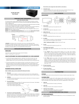
R90-20K front view
R90-20KVA rear view diagram

Xtreme Power Conversion Corporaon
R90 User’s Manual
Page 8
Uninterrupble Power Supply
EBP32 rear panel
R90-20K UPS + R90-EBP32 mounted in a rack

Xtreme Power Conversion Corporaon
R90 User’s Manual
Page 9
Uninterrupble Power Supply
Shelf shipped with UPS & EBP32 for mounng in a rack
Note: this shelf must be used in order to support the weight of the equipment. Do not install UPS or EBP32 into a
rack without using this shelf
Front panel

Xtreme Power Conversion Corporaon
R90 User’s Manual
Page 10
Uninterrupble Power Supply
Installaon Notes
• Place the UPS in a clean, stable environment, avoiding vibraon, dust, humidity, ammable gas and liquid,
corrosive objects, etc. Check the operang temperature of the room where the UPS is being installed to
assure it is within range of UPS specicaon.
• Baeries should be installed in an environment where the temperature is within the required specica-
ons of the product. Temperature is a major factor in determining baery life and capacity. Normal baery
installaon requires the temperature be maintained from 15°C to 25°C. Keep baeries away from heat
sources and main air venlaon areas.
WARNING!
Typical baery performance data is quoted for an operang temperature between 20°C and 25°C. Operang above
this range will reduce the baery life while operaon below this range will reduce the baery capacity.
If the equipment is not to be installed immediately, it must be stored in a room so as to protect it against excessive
heat and humidity sources.
CAUTION!
An unused baery must be recharged every 6 months. Temporarily connecng the UPS to a suitable AC source and
acvang the UPS for the me required to recharge the baeries is required.
• To monitor the UPS with the soware, simply connect the RS232 cable to the UPS and to a computer.
External Protecve Devices
For safety reasons, it is necessary to install an external circuit breaker at the input AC ulity and to the baery.
External Baery
The UPS and its associated baeries are protected against the eect of over-current through a DC compable
thermo-magnec circuit breaker located close to the baery.
UPS Output
Any external distribuon board used for load distribuon shall be ed with protecve devices so as to avoid the
risk of UPS overload.
Over-Current Protecon
A protecon device shall be installed at the distribuon panel of the incoming ulity power, and should idenfy
the power cables current capacity as well as the overload capacity of the system.
CAUTION!
Select a thermo magnec circuit-breaker with an IEC 60947-2 trip curve C (normal) for 125% of the current as listed
below. 40A Input Circuit Breaker required

Xtreme Power Conversion Corporaon
R90 User’s Manual
Page 11
Uninterrupble Power Supply
Power Cables
The cable design shall comply with the voltages and currents provided in this secon, and in accordance with local
electrical codes.
WARNING!
UPON STARTING, PLEASE ENSURE THAT YOU ARE AWARE OF THE LOCATION AND OPERATION OF THE EXTERNAL
ISOLATORS WHICH ARE CONNECTED TO THE UPS INPUT/BYPASS SUPPLY OF THE UTILITY DISTIRBUTION PANEL.
CHECK TO SEE IF THESE SUPPLIES ARE ELECTRICALLY ISOLATED, AND POST ANY NECESSARY WARNING SIGNS TO
PREVENT ANY INADVERTENT OPERATION
Cable Sizes
UPS MODEL
CABLE SIZES (THHW wiring at 75°C)
AC INPUT AC OUTPUT DC INPUT GROUNDING
R90-20K 8 awg 8 awg 6 awg 8 awg
CAUTION!
Protecve earth ground cable: connect each cabinet to an earth ground, following the shortest route possible.
WARNING!
FAILURE TO FOLLOW ADEQUATE GROUNDING PROCEDURES MAY RESULT IN ELECTROMAGNETIC INTERFERENCE
OR IN HAZARDS INVOLVING ELECTRICAL SHOCK AND FIRE.
Power Cables Connecon
Aer the equipment has been properly posioned and secured, connect the power cables as described below.
Verify the UPS is totally isolated from its external power source and all circuit breakers to the UPS are open. Check
to see that everything is electrically isolated, and post any necessary warning signs to prevent inadvertent opera-
on of the breakers.

Xtreme Power Conversion Corporaon
R90 User’s Manual
Page 12
Uninterrupble Power Supply
Power cable connecon diagram
Select the appropriate power cable size, paying aenon to the diameter of the connecon terminal of the cable,
which should be greater than or equal to the connecon posts.
Wiring diagram

Xtreme Power Conversion Corporaon
R90 User’s Manual
Page 13
Uninterrupble Power Supply
WARNING!
IF THE LOAD EQUPMENT IS NOT READY TO ACCEPT POWER WHEN THE UPS INSTALLATION IS OCCURING, ENSURE
THAT THE UPS OUTPUT CABLES ARE SAFELY ISOLATED AT THE CABLE ENDS.
CAUTION!
The earth ground and neutral bonding arrangement must be in accordance with local and/or naonal electrical
code pracces.
Baery Connecon
The UPS has a posive and negave double baery framework using a total of 32 baeries in series. A neutral
cable is retrieved from the joint between the cathode of the 16th and the anode of the 17th of the baeries. The
neutral cable, the baery posive cable, and the baery negave cable are then connected with the UPS. The
baeries between the anode and neutral connecon are called posive baeries, and the baeries between the
neutral and cathode are called the negave baeries. The connecon is shown in the diagram below.
± 192VDC baery connecon diagram internal EBP32
Note: The BAT + of the UPS Connecon Terminals is connected to the anode of the Posive Baery. The BAT – of
the UPS Connecon Terminals is connected to the cathode of the Posive Baery and the anode of the Negave
Baery. The BAT – is connected to the cathode of the Negave Baery.
Factory default sengs for the baery quanty is 32 pieces and for a baery capacity of 7AH (charger current =
1A programmable to 6A)

Xtreme Power Conversion Corporaon
R90 User’s Manual
Page 14
Uninterrupble Power Supply
Note: Oponal 3rd party baery conguraons of ±192VDC/±204VDC/±216VDC/±240VDC can be used and are
available.
CAUTION!
Ensure correct polarity of the baery string series connecon (i.e. inter-er and inter block connecons are from
(+) to (-) terminals. DO NOT mix baeries with dierent capacity or dierent brands, or new or old baeries.
WARNING!
ENSURE CORRECT POLARITY OF STRING END CONNECTIONS TO THE BATTERY CIRCUIT BREAKER, AND FROM THE
BATTERY CIRCUIT BREAKER TO THE UPS TERMINALS (I.E. (+) TO (+) / (-) TO (-)). DISCONNECT ONE OR MORE
BATTERY CELL LINKS IN EACH TIER. DO NOT RECONNECT THESE LINKS AND DO NOT CLOSE THE BATTERY CIRCUIT
BREAKER UNLESS ALL CONNECTIONS ARE PROPERLY CHECKED AND APPROVED.
R90-20K to EBP32 baery connecon

Xtreme Power Conversion Corporaon
R90 User’s Manual
Page 15
Uninterrupble Power Supply
UPS Mul-Module Installaon
The basic installaon procedure for a parallel system consisng of two or more R90-20KVA modules is that same
as that of a single module. The following provides installaon procedures related to a parallel system.
Cabinet Installaon
Connect all R90-20KVA UPS required in the parallel system as shown in the diagram below.
Note: If installing 5-6 units in parallel, remove the jumper cap J30 on the control inspecon board (MHTBJHR-
1CU04 in all UPS to be connected in parallel. If installing 7-10 units in parallel, remove the jumper cap J30/J31
on the control inspecon board (MHTBJHR1CU04 in all UPS to be connected in parallel. Make sure that each UPS
input breaker is in the “OFF” posion and there is no output from any UPS connected. The baery strings can be
connected separately or in parallel.
WARNING!
MAKE SURE THE N, A(L1), B(L2), AND C(L3) WIRING IS CORRECT, AND THAT GROUND IS CONNECTED.

Xtreme Power Conversion Corporaon
R90 User’s Manual
Page 16
Uninterrupble Power Supply
Parallel Cable Installaon
The shielded and double insulated control cables must be interconnected in a ring-conguraon between UPS
modules as shown in the diagram below. The parallel control board is mounted in each UPS module. The ring-
conguraon ensures high-reliability of the control funcon.
Parallel connecon of UPS

Xtreme Power Conversion Corporaon
R90 User’s Manual
Page 17
Uninterrupble Power Supply
Remote Emergency Power O (EPO) for Parallel Systems
EPO for parallel systems must be connected in parallel and installed as shown below. Once the EPO funcon of one
of the UPS in the parallel system is acvated, the UPS will send out a remote command and shut down the other
UPS’s in the parallel system.
CAUTION!
The remote emergency kill switch must be voltage-free and “normally open”.
EPO connecons for parallel systems

Xtreme Power Conversion Corporaon
R90 User’s Manual
Page 18
Uninterrupble Power Supply
Requirements for a Parallel System
A group of parallel UPS modules behave as one large UPS system with the advantage of presenng higher reli-
ability. In order to assure that all modules are equally ulized and comply with relevant wiring regulaons, please
follow the requirements below.
1. All UPS modules must be of the same rang and be connected to the same bypass source.
2. The Bypass and Ulity input sources must be referenced to the same neutral potenal.
3. The outputs of all the UPS modules must be connected to a common output bus.
4. The length and specicaon of power cables including the bypass input cables and the UPS output cabi-
nets should be the same size. This facilitates load sharing when operang in bypass mode.
5. Up to 10 UPS modules may be paralleled with common baery if desired
Note: If installing 5-6 units in parallel, remove the jumper cap J30 on the control inspecon board (MHTBJHR-
1CU04 in all UPS to be connected in parallel. If installing 7-10 units in parallel, remove the jumper cap J30/J31 on
the control inspecon board (MHTBJHR1CU04 in all UPS to be connected in parallel.
Operaon
Operaon Modes
The UPS is a double-conversion online UPS that may operate in the following alternave modes.
Normal Mode
The recer / charger derives power from the AC input ulity and supplies DC power to the inverter while oang
and boost charging the baery simultaneously. The inverter then converts the DC power to AC power and supplies
the load.
Baery Mode (stored energy mode)
If the AC input ulity power fails, the inverter, which is operang from power supplied by the baery, supplies the
crical AC loads with power from the baeries. There is no power interrupon to the crical load. The UPS will
automacally return to Normal Mode when AC input ulity recovers.
Bypass Mode
If the inverter is not funconing correctly, or if an overload occurs, the stac transfer switch will be acvated to
transfer the load from the inverter supply to bypass supply without interrupon to the crical load. In the event
that the inverter output is not synchronized with the bypass AC source, the stac switch will perform a transfer of
the load from the inverter to the bypass with power interrupon to the crical AC loads. This is to avoid paralleling
of unsynchronized AC sources. This interrupon is programmable but typically set to be less than one electrical
cycle (less than 15ms at 50Hz or less than 13.3ms at 60Hz).
ECO Mode
When the UPS is in AC Model and the requirement to the load is not crical, the UPS can be set to ECO Mode in
order to increase the eciency of the power supplied. In ECO Mode, the UPS works in line-interacve mode, so
the UPS will transfer to bypass ulity. When the AC is out of the set window, the UPS will transfer from bypass to
inverter and supply power from the baeries, with the LCD displaying all related informaon.
Note: ECO mode is not available in parallel system conguraons.
Parallel Redundancy Mode (system expansion)
To achieve higher capacity and / or increase reliability, the output of up to ten (10) UPS modules can be pro-
grammed to operate in parallel, with the built-in parallel controller in each UPS ensuring automac load sharing.

Xtreme Power Conversion Corporaon
R90 User’s Manual
Page 19
Uninterrupble Power Supply
Turn On / O the UPS
Connecng with Ulity
The UPS is a double-conversion online UPS that may operate in the following alternave modes.
CAUTION!
MAKE SURE PROPER GROUNDING IS IN PLACE.
• Set the Baery Breaker to the “ON” posion according to the user manual.
• Switch “ON” the UPS
CAUTION!
Check to see if the load is safely connected to the output of the UPS. If the load is not ready to receive power from
the UPS, make sure that it is safely isolated from the UPS output terminals.
The internal fan of the UPS will start spinning; the UPS will perform self-diagnoscs unl the unit beeps twice to
show the UPS is normal. The UPS then goes to bypass, Ulity LED and Bypass LED turn Green, the inverter is now
starng. When the inverter is checked “normal”, the UPS goes to Normal Mode and the load is supplied power by
the inverter.
Cold Start Procedure
CAUTION!
Follow these procedures when there is an input AC Ulity Failure but the baeries are normal.
• Turn on the baery switch.
o The baery will feed the Auxiliary power board.
• Trigger the Cold Start Buons of the modules respecvely using the ON BUTTON shown in the above dia-
gram.
o When baery is normal, the recer starts operaon. 30 seconds later the inverter starts and
operates, INV and Output light up.
CAUTION!
Wait for approximately 30 seconds before pressing the ON BUTTON.

Xtreme Power Conversion Corporaon
R90 User’s Manual
Page 20
Uninterrupble Power Supply
Inverter O
When the Ulity is normal, press OFF BUTTON for approximately 1 second unl you hear a beep. The INVERTER
LED will exnguish, the BYPASS LED will be illuminated, then the UPS turns to bypass supply.
Disconnecng from Ulity
CAUTION!
This procedure should be followed to completely shut down the UPS and the LOAD. Aer all power switches, isola-
tors, and circuit breakers are opened, there will be no output power from the UPS.
• Aer the inverter is o, turn the Ulity and Baery breakers to “OFF”. The LCD display will exnguish com-
pletely and the fan stops spinning in 60 seconds. If there are external baery packs connected, turn the
Baery breakers on each baery pack to the “OFF” posion.
WARNING!
Wait about 5 minutes for the internal DC bus bar capacitors to be completely discharged.
Computer Access
• Connect one end of the RS232 communicaons cable to a computer and the other end to the RS232 port
on the UPS
• Open the soware Muser4000, and choose “system” buon
/