Page is loading ...

UPS
Uninterruptible Power Supply
TRITON M3, 100 200 kVA
Operating Manual V 1.0
Article Numbers:
ACX33TRS100Kxxxx
ACX33TRS120Kxxxx
ACX33TRS160Kxxxx
ACX33TRS200Kxxxx

Contents
1.Safety ............................................................................................................................................................ 2
1.1 Safety notes ....................................................................................................................................... 2
1.2 Symbols used in this guide ............................................................................................................ 2
2.Main Features ............................................................................................................................................. 3
2.1 Summarization ................................................................................................................................... 3
2.2 Functions and Features .................................................................................................................. 3
3.Installation ................................................................................................................................................... 4
3.1 Unpack checking............................................................................................................................... 4
3.2 The appearance of the product ..................................................................................................... 4
3.3 LCD control panel ........................................................................................................................... 10
3.4 Installation notes............................................................................................................................. 10
3.5 External Protective Devices ......................................................................................................... 11
3.6 Power Cables ................................................................................................................................... 11
3.7 Power cable connect ...................................................................................................................... 12
3.8 Battery connection ......................................................................................................................... 13
3.9 UPS Multi-Module Installation ................................................................................................... 14
3.10 LBS installation ............................................................................................................................. 15
4.Operation ................................................................................................................................................... 17
4.1 Operation Modes ............................................................................................................................. 17
4.2 Turn on/off UPS ............................................................................................................................... 18
4.3 The Display ....................................................................................................................................... 21
4.4 Options .............................................................................................................................................. 25
Appendix 1 Specifications .......................................................................................................................... 26
Appendix 2 Problems and Solution .......................................................................................................... 28
Appendix 3 RS232 communication port definition ............................................................................... 30
Appendix 4 USB communication port definition .................................................................................. 31
Appendix 6 LBS communication port definition ................................................................................... 34
Appendix 7 BAT_T communication port definition .............................................................................. 35
Appendix 8 Drycontact port definition ..................................................................................................... 36
Appendix 9 REPO instruction .................................................................................................................... 37

1.Safety
Important safety instructions – Save these instructions
There exists dangerous voltage and high temperature inside the UPS. During the
installation, operation and maintenance, please abide the local safety instructions and relative
laws, otherwise it will result in personnel injury or equipment damage. Safety instructions in this
manual act as a supplementary for the local safety instructions. Our company will not assume
the liability that caused by disobeying safety instructions.
1.1 Safety notes
1. Even no connection with utility power, 220/230/240VAC voltage may still exist at UPS outlet!
2. For the sake of human being safety, please well earth the UPS before starting it.
3.Don’t open or damage battery, for the liquid spilled from the battery is strongly poisonous and
do harmful to body!
4.Please avoid short circuit between anode and cathode of battery, otherwise, it will cause
spark or fire!
5.Don’t disassemble the UPS cover, or there may be an electric shock!
6.Check if there exists high voltage before touching the battery
7.Working environment and storage way will affect the lifetime and reliability of the UPS. Avoid
the UPS from working under following environment for long time
◆ Area where the humidity and temperature is out of the specified range(temperature 0
to 40℃, relative humidity 5%-95%)
◆ Direct sunlight or location nearby heat
◆ Vibration Area with possibility to get the UPS crashed.
◆ Area with erosive gas, flammable gas, excessive dust, etc
8.Keep ventilations in good conditions otherwise the components inside the UPS will be
over-heated which may affect the life of the UPS.
1.2 Symbols used in this guide
WARNING!
Risk of electric shock
CAUTION!
Read this information to avoid equipment damage

2.Main Features
2.1 Summarization
This series UPS is a kind of three-in-three-out high frequency online UPS, it provides seven
specifications: The 100~200kVA. The UPS can solve most of the power supply problems, such
as blackout, over-voltage, under-voltage, voltage sudden drop, oscillating of decreasing extent,
high voltage pulse, voltage fluctuation, surge, inrush current, harmonic distortion (THD), noise
interference, frequency fluctuation, etc..
This UPS can be applied to different applications from computer device, automatic
equipment, communication system to industry equipment.
2.2 Functions and Features
◆3Phase In/3Phase Out UPS
It is 3Phase In/3Phase Out high-density UPS system, of which input current is kept in balance.
No unbalance problem might occur.
◆Digital Control
This series UPS is controlled by Digital Signal Processor (DSP); enhance, it increases
reliability, performance, self-protection, and self-diagnostics and so on.
◆Battery Configurable from 32 blocks to 40 blocks
The battery voltage of this series UPS can be configured at 32 blocks, 34 blocks, 36 blocks, 38
blocks or 40 blocks according to your convenience.
◆Charging Current is configurable
The user may set the capacity of the batteries as well as reasonable charging current.
Constant voltage mode, constant current mode or floating mode can be switched automatically and
smoothly.
◆Intelligent charging Method
The series UPS adopts advanced three-stage charging method—
1
st
stage: high current constant current charging
To guarantee to charge back to 90%;
2
nd
-stage: Constant Voltage
In order to vitalize battery and make sure batteries are fully charged
3
rd
stage: floating mode.
With this 3-stage charging method, it extends the life of the batteries and guarantees fast charging.
◆LCD Display
With LCD plus LED displays, the user may easily get UPS status and its operational
parameters, such as input/output voltage, frequency & load%, battery % and ambient
temperature, etc...
◆Intelligent Monitoring Function
Via optional SNMP Card, you may remotely control and monitor the UPS.
◆EPO Function
The series UPS may be completely shut off when the EPO is pressed. REPO function
(Remote EPO) is also available in this series UPS.

3.Installation
3.1 Unpack checking
1. Don’t lean the UPS when moving it out from the packaging
2. Check the appearance to see if the UPS is damaged or not during the transportation, do
not switch on the UPS if any damage found. Please contact the dealer right away.
3. Check the accessories according to the packing list and contact the dealer in case of
missing parts.
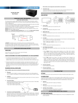
3.2 The appearance of the product
Front View Side View Rear View

HIP33100-33120
Front View(internal) Rear View(internal)

HIP33160
Front View(internal) Rear View(internal)

HIP33200
Front View(internal) Rear View(internal)
(1) LCD panel : LCD and LED display
(2) Front lock
(3) Lightning arrester cover plate : Remove cover plate to replace lightning arrester
(4) Bypass switch cover plate : Remove cover to operate bypass switch
(5) Dustproof net plate
(6) Fuse Box : Input fuses and Battery fuses inbuilt, box 1 connected to module 1
(7) Communication panel
(8) I/P Switch
(9) Maintenance switch
(10) Maintenance switch cover : Remove cover UPS transfers to Maintenance
(11) Input/Output Terminal cover : Remove cover to operate wire
(12) O/P Switch
(13) Lightning arrester

Communication panel:
Parallel port:
Terminal Block:
Dustproof net plate:
(14) Parallel port 1/2
(15) The input filter capacitor switch : connect capacitor or not
(16) Bypass Switch
(17) Update RS485 port : use to update UPS software
(18) LBS port
(1) Communication panel fixed screw
(2) Intelligent slot 1 : insert SNMP card or Dry contact card
(3) Intelligent slot 2 : insert SNMP card or Dry contact card
(4) RS485 port 1/2
(5) BAT_T port 1/2 : connect battery temperature sensor box
(6) Black start button : start UPS by battery without AC input
(7) EPO button
(8) REPO port : Remote EPO connect port
(9) RS232 port
(10) USB port
(11) Dry contact port : Pin1-12Vdc, Pin2- DRY_GENER , Pin3- BP_O, Pin4- BP_S

1-6:Dustproof net plate fixed screw

3.3 LCD control panel
LCD control panel introduction
(1)LED(from top to bottom: “mains output”, “bypass output”、“battery output”、“alarm”)
(2)LCD display
(3)Founction button
3.4 Installation notes
Note: Consider for the convenience of operation and maintenance, the space in
front and back of the cabinet should be left at least 100cm and 80cm respectively when
installing the cabinet.
◆Please place the UPS in a clean, stable environment; avoid the vibration, dust, humidity,
flammable gas and liquid, corrosive. To avoid from high room temperature, a system of room
extractor fans is recommended to be installed. Optional air filters are available if the UPS operates
in a dusty environment.
◆The environment temperature around UPS should keep in a range of 0℃~40℃. If the
environment temperature exceeds 40℃, the rated load capacity should be reduced by 12% per
5℃. The max temperature can't be higher than 50℃.
◆If the UPS is dismantled under low temperature, it might be in a condensing condition. The
UPS can't be installed unless the internal and external of the equipment is fully dry. Otherwise,
there will be in danger of electric shock.
◆Batteries should be mounted in an environment where the temperature is within the required
specs. Temperature is a major factor in determining battery life and capacity. In a normal
installation, the battery temperature is maintained between 15°C and 25°C. Keep batteries away
from heat sources or main air ventilation area, etc.
WARNING!
Typical battery performance data are quoted for an operating temperature between
20°C and 25°C. Operating it above this range will reduce the battery life while
operation below this range will reduce the battery capacity.
◆Should the equipment not be installed immediately it must be stored in a room so as to
protect it against excessive humidity and or heat sources。
CAUTION!
An unused battery must be recharged every 6months temporarily connecting the
UPS to a suitable AC supply mains and activating it for the time required for
recharging the batteries.

◆The highest altitude that UPS may work normally with full load is 1500 meters. The load
capacity should be reduced when this UPS is installed in place whose altitude is higher than 1500
meters, shown as the following table:
(Load coefficient equals max load in high altitude place divided by nominal power of the
UPS)
Altitude(m)
1500
2000
2500
3000
3500
4000
4500
5000
Load coefficient
100%
95%
90%
85%
80%
75%
70%
65%
◆The UPS cooling is depending on fan, so it should be kept in good air ventilation area.
There are many ventilation holes on the front and rear, so they should not be blocked by any exotic
obstacles.
3.5 External Protective Devices
For safety reasons, it is necessary to install, external circuit breaker at the input A.C. supply and
the battery. This chapter provides guidelines for qualified installers that must have the knowledge of
local wiring practices for the equipment to be installed.
◆External Battery
The UPS and its associated batteries are protected against the effect of over-current
through a DC compatible thermo-magnetic circuit-breaker (or a set of fuses) located close to
the battery.
◆UPS Output
Any external distribution board used for load distribution shall be fitted with protective
devices that may avoid the risk of UPS overloaded.
◆Over-current
Protection device shall be installed at the distribution panel of the incoming main supply. It
may identify the power cables current capacity as well as the overload capacity of the system.
3.6 Power Cables
◆The cable design shall comply with the voltages and currents provided in this section, Kindly
follow local wiring practices and take into consideration the environmental conditions
(temperature and physical support media).
WARNING!
UPON STARTING, PLEASE ENSURE THAT YOU ARE AWARE OF THE
LOCATION AND OPERATION OF THE EXTERNAL ISOLATORS WHICH ARE
CONNECTED TO THE UPS INPUT/BYPASS SUPPLY OF THE MAINS
DISTRIBUTION PANEL.CHECK TO SEE IF THESE SUPPLIES ARE ELECTRICALLY
ISOLATED, AND POST ANY NECESSARY WARNING SIGNS TO PREVENT ANY
INADVERTENT OPERATION
◆For future expansion purpose, it is economical to install power cable according to the full rating
capacity initially. The diameter of cable is shown bellow:

UPS
cabinet
Cable Dimension
AC Input
(mm
2
)
AC Output
(mm
2
)
DC Input
(mm
2
)
Grounding
(mm
2
)
100
95
95
120
95
120
120
120
150
120
160
150
150
185
150
200
185
185
240
185
CAUTION!
Protective earth cable: Connect each cabinet to the main ground system. For
Grounding connection, follow the shortest route possible。
WARNING!
FAILURE TO FOLLOW ADEQUATE EARTHING PROCEDURES MAY
RESULT IN ELECTROMAGNETIC INTERFERENCE OR IN HAZARDS
INVOLVING ELECTRIC SHOCK AND FIRE
3.7 Power cable connect
Once the equipment has been finally positioned and secured, connect the power cables as
described in the following procedure.
Verify the UPS is totally isolated from its external power source and also all power isolators of
the UPS are open. Check to see if they are electrically isolated, and post any necessary warning
signs to prevent their inadvertent operation.
Open the UPS terminal panel; remove the cover of terminals for wiring easily.
Terminal Block:
Terminal sequence from left to right: input phase A(L1),input phase B(L2),input phase
C(L3),input Neutral line, output Neutral line, output phase A(L1), output phase B(L2), output phase
C(L3);battery positive, battery Neutral, battery negative,Ground,bypass input phase A(L1),bypass
input phase B(L2),bypass input phase C(L3)。
Choose appropriate power cable.(Refer to the table above)and pay attention to the
diameter of the connection terminal of the cable that should be greater than or equal to that of
the connection poles;
Wiring

WARNING!
If the load equipment is not ready to accept power on the arrival of the
commissioning engineer then ensure that the system output cables are
safely isolated at their ends
Connect the safety earth and any necessary bonding earth cables to
the copper earth screw located on the floor of the equipment below the
power connections. All cabinets in the UPS must be grounded properly.
CAUTION!
The earthing and neutral bonding arrangement must be in accordance
with local and national codes of practice.
3.8 Battery connection
The UPS adopts positive and negative double battery framework, total 32(optional 34/36/38/40)
in series. A neutral cable is retrieved from the joint between the cathode of the 16
th
(17
th
/18
th
/19
th
/20
th
)
and the anode of the 17
th
(18
th
/19
th
/20
th
/21
th
) of the batteries. Then the neutral cable, the battery
Positive and the battery negative are connected with the UPS respectively. The battery sets between
the Battery anode and the neutral are called positive batteries and that between neutral and cathode
are called negative ones. The user can choose the capacity and the numbers of the batteries
according to their desire.

Note:
The BAT+ of the UPS connect poles is connected to the anode of the positive
battery, the BAT-N is connected to the cathode of the positive battery and the anode
of the negative battery, the BAT- is connected to the cathode of the negative battery。
Factory setting of the long-run unit is battery quantity---32pcs, battery
capacity---12V65AH. When connecting 32/34/38/40 batteries, please re-set desired
battery quantity and its capacity after UPS starts at AC mode. Charger current could
be adjusted automatically according to battery capacity selected. All related settings
can be done through LCD panel or monitoring software.
CAUTION!
Ensure correct polarity battery string series connection. I.e. inter-tier
and inter block connections are from (+) to (-) terminals.
Don’t mix batteries with different capacity or different brands, or
even mix up new and old batteries, either.
WARNING!
Ensure correct polarity of string end connections to the Battery
Circuit Breaker and from the Battery Circuit Breaker to the UPS
terminals i.e. (+) to (+) / (-) to (-) but disconnect one or more battery cell
links in each tier. Do not reconnect these links and do not close the
battery circuit breaker unless authorized by the commissioning
engineer.
3.9 UPS Multi-Module Installation
The basic installation procedure of a parallel system comprising of two or more UPS modules is
the same as that of single module system. The following sections introduce the installation
procedures specified to the parallel system.
3.9.1 Cabinet installation
Connect all the Uses needed to be put into parallel system as below picture.

Make sure each UPS input breaker is in “off” position and there is no any output from each
UPS connected. Battery groups can be connected separately or in parallel, which means the
system itself provides both separate battery and common battery.
WARNING!
Make sure the N、A(L1)、B(L2)、C(L3)lines are correct, and grounding
is well connected.
3.9.2 Parallel cable installation
Shielded and double insulated control cables available must be interconnected in a ring
configuration between UPS modules as shown below. The parallel control board is mounted on
each UPS module. The ring configuration ensures high reliability of the control.
3.10 LBS installation
LBS system contains LCD set, cable connect and STS device.

3.10.1 LCD setting
Set every UPS of the systems to be LBS Master or LBS Slave. For instance if the UPS
belongs to LBS master system, its LBS setting must be set to Master.
3.10.2 LBS cable installation
The two ports of one mesh wire should be plug into RJ45 interface of any one UPS of both
master and slave system.
3.10.3 UPS installation
The whole systems is showed below.
UPS_1
UPS_2
UPS_N
Input Output
UPS_1
UPS_2
UPS_M
Input Output
STS
MASTER
SLAVE
Load
M、N>=1

4.Operation
4.1 Operation Modes
The UPS is a double-conversion on-line UPS that may operate in the following alternative
modes:
◆Normal mode
The rectifier/charger derives power from the AC Mains and supplies DC power to the inverter
while floating and boosting charge the battery simultaneously. Then, the inverter converts the DC
power to AC and supplies to the load.
◆Battery mode (Stored Energy Mode)
If the AC mains input power fails, the inverter, which obtains power from the battery, supplies the
critical AC load. There is no power interruption to the critical load. The UPS will automatically return to
Normal Mode when AC recovers.
◆Bypass mode
If the inverter is out of order, or if overload occurs, the static transfer switch will be activated to
transfer the load from the inverter supply to bypass supply without interruption to the critical load. In
the event that the inverter output is not synchronized with the bypass AC source, the static switch will
perform a transfer of the load from the inverter to the bypass with power interruption to the critical AC
load. This is to avoid paralleling of unsynchronized AC sources. This interruption is programmable
but typically set to be less than an electrical cycle e.g. less than 15ms (50Hz) or less than 13.33ms
(60Hz).
◆ECO Mode
When the UPS is at AC Mode and the requirement to the load is not critical, the UPS can be set
at ECO mode in order to increase the efficiency of the power supplied. At ECO mode, the UPS
works at Line-interactive mode, so the UPS will transfer to bypass supply. When the AC is out of set
window, the UPS will transfer from bypass to Inverter and supplies power from the battery, and then
the LCD shows all related information on the screen.
◆Parallel redundancy mode (system expansion)
To achieve a higher capacity and / or increase reliability, the outputs of up to four UPS modules
can be programmed to operate in parallel and the built-in parallel controller in each UPS ensures
automatic load sharing.
◆LBS (Load Bus Synchronization)
The function of LBS is to keep the output of two independent UPS systems (single unit or multiple unit)
in synchronization even when the two systems are operating on different modes (bypass/inverter) or on
batteries. It is usually used with an STS (Static Transfer Switch) connected to the critical load to achieve Dual
Bus configuration.
◆Maintenance mode (Manual Bypass)

A manual bypass switch is available to ensure continuity of supply to the critical load when the
UPS is out of order or in repair and this manual bypass switch bears for equivalent rated load.
4.2 Turn on/off UPS
4.2.1 Restart procedure
CAUTION!
MAKE SURE GROUNDING IS PROPERLY DONE!
◆ Set the Battery Breaker to the “ON” position according to the user’s manual.
◆ Open the front and rear doors of the UPS to access to the main power switches. During
this procedure the output terminals will become alive.
CAUTION!
Check to see if the load is safely connected with the output of the UPS. If the
load is not ready to receive power from the UPS, make sure that it is safely
isolated from the UPS output terminals
CAUTION!
Be sure that the maintenance cover is closed well before turn on the UPS!
◆ UPS Input Switch (below the UPS module at the front door)
If the Rectifier input is within voltage range, the rectifier will start up in 30 seconds then
the inverter will start up after then.
◆ UPS Output Switch (below the UPS module at the front door)
If the rectifier fails at startup, the bypass LED will light up. When the inverter starts up,
the UPS will transfer from bypass mode to inverter mode, and then the bypass LED
extinguishes and the inverter LED lights up.
No matter whether the UPS can work normally or not, all the status will be shown on the
LCD display.
4.2.2 Test procedure
CAUTION!
The UPS is operating normally.
It may take 60 seconds to boost up the system and perform self-test completely.
◆ Switch off the MAINS to simulate utility failure, the rectifier will turn off and the battery

should feed the inverter without interruption. At this time, the LEDs of battery should be
turned on.
◆ Switch on the MAINS to simulate utility recovery, the rectifier will restart automatically after
20 seconds and the inverter will supply to the load. It is suggested to use Dummy loads
for testing. The UPS can be loaded up to its maximum capacity during load test。
4.2.3 MAINTENANCE BYPASS
To supply the load via Mains, you may simply active the internal mechanical bypass switch.
CAUTION!
The load is not protected by the UPS when the internal mechanical bypass system is
active and the power is not conditioned.
Switch to mechanical bypass
CAUTION!
If the UPS is running normally and can be controlled through the display, carry out
steps 1 to 5; otherwise, jump to Step 4.
◆ Open the cover of maintenance switch, the UPS turns to bypass mode
automatically.
◆ Switch on MAINTENANCE breaker;
◆ Switch OFF BATTERY breaker;
◆ Switch OFF the MAINS breaker,
◆ Switch OFF OUTPUT breaker;
At this time the bypass source will supply to the load through the MAINTENANCE
breaker.
Switch to normal operation (from mechanical bypass)
CAUTION!
Never attempt to switch the UPS back to normal operation until you have verified
that there are no internal UPS faults
CAUTION!
Be sure that the maintenance cover is closed well before turn on the UPS!
◆ Open the front door of the UPS to be easily access to the main power switch.
/