Page is loading ...

1 / 8
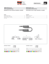
PL-PC-1021SET
14.5252-*
PL-PC-1021SET-CN
14.5253-*
WA-ID/S21
14.0050
ID/S21-C...
14.0049C...
MS-S21
14.0104
VK-S21
15.5860
MA075 (de_en)
Montageanleitung
MA075 (de_en)
Assembly instructions
Einbaudosen-Stecker ID/S21-C...
mit Bajonettverriegelung und
Gewindeanschluss M20
Panel receptacle plug ID/S21-C...
with bayonet locking and
threaded stud M20
Inhalt
Sicherheitshinweise................................................................ 2-3
Erforderliches Werkzeug �����������������������������������������������������������4
Steckverbindermontage an Fronttafel ���������������������������������������4
Anschluss ����������������������������������������������������������������������������������5
Steckverbindermontage mit Winkeladapter ������������������������������5
Montage des Schutzdeckels �����������������������������������������������������6
Montage des Mikroschalters ����������������������������������������������������� 6
Funktionskontrolle des Mikroschalters �������������������������������������� 6
Montage des Schutzdeckels VK-S21 �����������������������������������������6
Kodierung ����������������������������������������������������������������������������������7
Steckvorgang / Prüfvorgang / Trennvorgang ��������������������������7-8
Verriegelunsstift �������������������������������������������������������������������������8
Dichtung an KBT21 prüfen ��������������������������������������������������������8
Content
Safety Instructions .................................................................. 2-3
Tools required ����������������������������������������������������������������������������4
Connector assembly in front panel ��������������������������������������������4
Termination �������������������������������������������������������������������������������� 5
Connector assembly in angle departure ������������������������������������ 5
Protective cover assembly ��������������������������������������������������������� 6
Installation of microswitch ��������������������������������������������������������6
Functional check of microswitch ����������������������������������������������6
Protective cover VK-S21 assembly ������������������������������������������� 6
Coding ���������������������������������������������������������������������������������������7
Plugging, test and unplugging procedures ����������������������������7-8
Locking pin ��������������������������������������������������������������������������������8
Check KBT21 seal ���������������������������������������������������������������������� 8

2 / 8
Sicherheitshinweise Safety instructions
Die Montage und Installation der Produkte darf ausschließlich
durch Elektrofachkräfte oder elektrotechnisch unterwiesene
Personen unter Berücksichtigung aller anwendbaren gesetz-
lichen Sicherheitsbestimmungen und Regelungen erfolgen�
Stäubli Electrical Connectors (Stäubli) lehnt jegliche Haftung
infolge Nichteinhaltung dieser Warnhinweise ab�
The products may be assembled and installed by electrically
skilled or instructed personnel duly observing all applicable
safety regulations�
Stäubli Electrical Connectors (Stäubli) does not accept any lia-
bility in the event of failure to observe these warnings�
Benutzen Sie nur die von Stäubli angegebenen Einzelteile und
Werkzeuge� Weichen Sie nicht von den hier beschriebenen
Vorgängen zur Vorbereitung und Montage ab, da sonst bei der
Selbstkonfektionierung weder die Sicherheit noch die Einhal-
tung der technischen Daten gewährleistet ist� Ändern Sie das
Produkt in keiner Weise ab�
Only use the components and tools specied by Stäubli. In
case of self-assembly, do not deviate from the preparation
and assembly instructions as stated herein, otherwise Stäubli
cannot give any guarantee as to safety or conformity with the
technical data� Do not modify the product in any way�
Nicht von Stäubli hergestellte Steckverbindungen, die mit
Stäubli-Elementen steckbar sind und von einigen Herstellern
manchmal auch als „Stäubli-kompatibel“ bezeichnet werden,
entsprechen nicht den Anforderungen für eine sichere, lang-
zeitstabile elektrische Verbindung und dürfen aus Sicherheits-
gründen nicht mit Stäubli-Elementen gesteckt werden� Stäubli
übernimmt daher keine Haftung, falls diese von Stäubli nicht
freigegebenen Steck verbindungen mit Stäubli-Elementen ge-
steckt werden und deshalb Schäden entstehen�
Connectors not originally manufactured by Stäubli which can
be mated with Stäubli elements, and in some cases are even
described as ”Stäubli-compatible” by certain manufacturers,
do not conform to the requirements for safe electrical connec-
tion with long-term stability, and for safety reasons must not
be plugged together with Stäubli elements� Stäubli therefore
does not accept any liability for any damage resulting from
mating such connectors (i�e� lacking Stäubli approval) with
Stäubli elements�
Caution, risk of electric shock
(IEC 60417-6042)
Arbeiten im spannungsfreien Zustand
Die fünf Sicherheitsregeln sind bei Arbeiten an elektrischen
Installationen zu beachten�
Nachdem die betroffenen Anlagenteile festgelegt sind,
müssen die folgenden fünf wesentlichen Anforderungen in
der angegebenen Reihenfolge eingehalten werden, sofern es
nicht wichtige Gründe gibt, davon abzuweichen:
– Freischalten;
– gegen Wiedereinschalten sichern;
– Spannungsfreiheit feststellen;
– Erden und Kurzschliessen;
– benachbarte, unter Spannung stehende Teile abdecken oder
abschranken�
Alle an der Arbeit beteiligten Personen müssen Elektrofach-
kräfte oder elektrotechnisch unterwiesene Personen sein
oder unter Aufsichtsführung einer solchen Person stehen�
Quelle: EN 50110-1:2013 (DIN EN 50110-1, VDE 0105-1)
Work in a de-energized state
Follow the ve safety rules, when working on electrical instal-
lations�
After the respective electrical installations have been identi-
ed, the following ve essential requirements shall be under-
taken in the specied order unless there are essential reasons
for doing otherwise:
- disconnect completely;
- secure against re-connection;
- verify absence of operating voltage;
- carry out earthing and short-circuiting;
- provide protection against adjacent live parts�
Any person engaged in this work activity shall be electrically
skilled or instructed, or shall be supervised by such a person�
Source: EN 50110-1:2013
Der Schutz gegen elektrischen Schlag ist auch in den Endan-
wendungen zu prüfen�
Protection against electric shock shall be checked in the end-
use applications too�
Do not disconnect under load
(IEC 60417-6070)
Das Stecken und Trennen unter Spannung ist zulässig� Plugging and unplugging when live is permitted�

3 / 8
Sicherheitshinweise Safety instructions
Caution
(ISO 7000-0434B)
Vor jedem Gebrauch ist visuell zu prüfen, ob keine äußeren
Mängel vorhanden sind (besonders an der Isolation)� Wenn
Zweifel bezüglich der Sicherheit bestehen, muss ein Fach-
mann hinzugezogen oder der Steckverbinder ausgetauscht
werden�
Each time the connector is used, it should previously be ins-
pected for external defects (particularly the insulation)� If there
are any doubts as to its safety, a specialist must be consulted
or the connector must be replaced�
Die Steckverbinder sind wasserdicht gemäß der für das jewei-
lige Produkt angegebenen IP-Schutzart�
The plug connectors are watertight in accordance with the
product specic IP protection class.
Nicht gesteckte Steckverbinder sind vor Feuchtigkeit und
Schmutz zu schützen� Die Steckverbinder dürfen nicht in ver-
schmutztem Zustand miteinander gesteckt werden�
Unmated plug connectors must be protected from moisture
and dirt� The male and female parts must not be plugged to-
gether when soiled�
Die technischen Spezikationen des Steckverbinders variieren
gemäß der Klassizierung der Anlage, IEC oder UL (Bemes-
sungsspannung und -strom), siehe Produktkatalog�
The technical specications of the connector vary depending
on the system classication, IEC or UL (rated voltage and cur-
rent)� For more information, please see the product catalog�
Nützlicher Hinweis oder Tipp
Useful hint or tip
Weitere technische Daten entnehmen Sie bitte dem Produkt-
katalog�
For further technical data please see the product catalog�

4 / 8
2
3
1
5
4 x Ø6,5
Ø54
61
±0,2
61
±0,2
4
Erforderliches Werkzeug Tools required
(ill. 1)
Drehmomentschlüssel SW30, 52Nm
(ill. 1)
Torque wrench 30mm A/F, 52Nm
(ill. 2)
Gabelschlüssel:
- SW10
- SW30
(ill. 2)
Open-end spanner:
- 10mm A/F
- 30mm A/F
(ill. 3)
Kreuzschraubendreher Phillips,
Grösse 0 (wird für die Montage des
Mikroschalters benötigt)�
Drehmomentschraubenzieher 4Nm,
Bit Phillips Gr� 3
(ill. 3)
Cross-head screwdriver size 0 (re-
quired for micro-switch assembly)�
Torque screwdriver 4Nm, Phillips bit,
size 3�
Steckverbindermontage an
Fronttafel
Connector assembly in front
panel
(ill. 4)
Fronttafel gemäß Bohrplan bohren�
(ill. 4)
Drill front panel according to drilling
plan�
(ill. 5)
Falls verwendet, den Farbring FR21
auf ID/S��� aufkleben�
(ill. 5)
If used, stick the coloured ring FR21
on ID/S���
Farbring
Coloured ring
Achtung
Vor dem Kleben:
1. Oberäche reinigen (trocken, sauber und frei von
Formtrennmittelrückständen).
2. Zum Entfernen von Staub, Fett oder Öl, folgenden
Lösungsmittel verwenden:
- Heptan (kein Aceton)
Einwirkzeit unter 5 Minuten (nie eintauchen)�
- Scotch (3M) Untergrundreiniger S-151 (70% Isopropylal-
kohol und 30% destilliertes Wasser)�
3. Oberäche trocknen.
Attention
Before bonding:
1. Clean the surface (dry, rm and free from moulding
parting-agent residues).
2. For the removal of dust, grease or oil we recom-
mend the following solvents:
- Heptane (no acetone) (do not immerse)� Cleaning effec-
tive for up to 5 minutes�
- Scotch (3M) surface cleanser S-151 (70% isopropyl
alcohol and 30% distilled water)�
3. Dry the surface.

5 / 8
6
W
4 5 6
7
7 4 5 6
8
4 x Ø6,5
Ø110
93± 0, 2
93± 0, 2
min. 3mm, max. 10mm
10
9
(ill. 6)
Dose von vorne in die Fronttafel
stecken und so ausrichten, dass die
Markierung W beim Steckvorgang gut
sichtbar ist�
Kreuzschlitzschrauben M6 und Mutter
M6 anziehen�
Anzugsdrehmoment 4Nm.
(ill.6)
Insert plug into front panel�
Align plug so that marking W is visible
during plugging�
Tighten Phillips screws M6 and nut
M6. Tightening torque 4Nm.
Anschluss Termination
(ill. 7)
Mutter 6, Federscheibe 5 und Unter-
lagscheibe 4 vom Gewinde lösen�
(ill. 7)
Remove the nut 6, lock washer 5 and
the washer 4 from the screw thread�
(ill. 8)
Kabelschuh mit angeschlossener
Leitung auf das Gewinde schieben�
Unterlagscheibe 4, Federscheibe 5
und Mutter 6 montieren� Mutter 6 mit
Drehmomentschlüssel SW30 anzie-
hen und mit Gabelschlüssel SW30
und Mutter 7 kontern�
Anzugsdrehmoment 52Nm
Hinweis:
Nicht an der Isolation kontern!
(ill. 8)
Slip cable lug with pre-assembled
cable onto the thread� Bring back the
nut 6, washer 4 and the lock washer 5
onto the screw thread�
Tighten nut 6 with the torque wrench
30mm A/F and secure it with nut 7
and the open-end spanner 30mm A/F.
Tightening torque 52Nm
Note:
Do not lock-tighten on the insula-
tion!
Steckverbindermontage mit
Winkeladapter
Connector assembly in ang-
led adapter
(ill. 10)
Fronttafel gemäß Bohrplan bohren�
Winkeladapter von vorne auf die
Fronttafel montieren, so dass der An-
schluss der ID/S nach unten gerichtet
ist�
Kreuzschlitzschrauben M6 und Mutter
M6 anziehen�
Anzugsdrehmoment 4Nm.
(ill. 10)
Drill the front panel according to the
drilling plan�
Mount angled adapter on the panel
from the front so that the ID/S con-
nection points downwards�
Tighten Phillips screws M6 and nuts
M6. Tightening torque 4Nm.

6 / 8
11
W
A
13
12
Druckpunkt
Actuator
Point de pression
c
(ill.11)
Stecker von vorne in den Winkelad-
apter stecken� Stecker so ausrichten,
dass die Markierung W beim Steck-
vorgang gut sichtbar ist�
Kreuzschlitzschrauben M6 und Mutter
M6 anziehen�
Anzugsdrehmoment 4Nm.
Anschluss siehe ill� 7, 8 Seite 5
(ill.11)
Insert plug into angled adapter�
Align plug so that marking W is visible
during plugging�
Tighten Phillips screws M6 and nuts
M6. Tightening torque 4Nm.
Connection see ill� 7, 8 page 5
Montage des Schutzdeckels Protective cover assembly
Hinweis:
Siehe Montageanleitung MA036
www.staubli.com/electrical
Note:
See assembly instructions MA036
www.staubli.com/electrical
Montage des Mikroschalters Installation of microswitch
(ill. 12)
Mikroschalter auf den Stecker mit PT-
Schrauben anschrauben�
Der Mikroschalter-Kontakt mit Um-
schaltkontakt hat 3 Steckanschlüsse
2�8 x 0�5 und eine Schaltleistung von
6A, 250 VAC.
Hinweis:
Montagerichtung des Mikroschal-
ters beachten!
(ill. 12)
Fasten microswitch to plug with PT-
screw� The microswitch contact is a
changeover contact� Type of con-
nection: 3 plug connectors 2�8 x 0�5,
switching capacity 6A, 250 VAC.
Note:
Check the orientation when as-
sembling the microswitch!
Funktionskontrolle des
Mikroschalters
Functional check of
microswitch
Der Mikroschalter schaltet unmittelbar
bevor die Verriegelung einrastet und
zeigt damit an, dass die Steckverbin-
dung verriegelt ist�
Hinweis:
Die korrekte Verriegelung ist erst
nach dem Einrasten sichergestellt.
By switching immediately prior to
engagement of the interlock, the
microswitch indicates that the plug
connection is engaged�
Note:
Correct interlocking is achieved
only after latching.
Montage des Schutzdeckels Protective cover assembly
(ill. 13)
Der Schutzdeckel wird von vorne in
den Stecker gesteckt bis zum An-
schlag� Die Gummischlaufe kann über
die Öse A festgeschraubt werden�
(ill. 13)
Push the protective cover into the
plug from the front as far as it will go�
Tighten the lanyard to the connector
through the eyelet A�

7 / 8
14
Bezeichnung
Designation
Symbol
Kodier-Nr.
Coding-No.
Farbe
Colour
(UL)
Phase 1 L1 C1 Braun / Brown
Phase 2 L2 C2 Orange oder violett / Orange or violet
Phase 3 L3 C3 Gold / Yellow
Neutral N C4 Weiss / White
Erde / Ground PE C5 Grün / Green
Reserve - C6
Gleichstrom / Direct current -/+ CM/CP
CM: schwarz / CP: rot
CM: black / CP: red
Kodierung Coding
Es gibt max� 7 mechanische Kodiermöglichkeiten, gekenn-
zeichnet mit C1 bis C6 und CM/CP�
Folgende Kodierzuordnung wird zur Sicherstellung der Aus-
wechselbarkeit empfohlen:
There is a maximum of 7 mechanically coding possibilities,
designated from C1 to C6 and CM/CP�
The following coding is recommended to safeguard the inter-
changeability:
Hinweis:
Es sind nur Stecker mit Buchsen steckbar, die die gleiche
Kodier-Nr. aufweisen.
Note:
Plugs can only be inserted into sockets with the same code
no.
Steckvorgang Plugging procedure
(ill. 14)
Der Verriegelungsstift auf der Buchsenseite muss auf Position
“offen” stehen (ill� 16, Seite 8)�
Zum Stecken müssen sich die Markierungen von Stecker und
Buchse gegenüberstehen� Steckverbindung bis zum Anschlag
zusammenstecken, dann die Buchse um 45° nach rechts dre-
hen, bis die Verriegelung einrastet�
Wenn gewünscht, Verriegelungsstift auf „geschlossen“ drehen
(ill� 17, Seite 8)�
(ill. 14)
The locking pin on the female connector must be in “open”
position (ill� 16, page 8)�
The markings on the plug and socket have to be lined up� Push
the plug into the socket and press against the plug’s spring re-
sistance until it stops� Turn the socket through 45° to the right
until the bayonet lock engages�
If desired, turn the locking pin to “closed“ position
(ill� 17, page 8)�
Prüfvorgang Test procedure
Durch Drehbewegung prüfen ob die Verriegelung im Eingriff
ist�
Durch Zug prüfen, ob die Verbindung in dieser Position mecha-
nisch nicht mehr getrennt werden kann�
By twisting the connectors test that the locking mechanism is
engaged�
By attempting to simply pull the connectors apart, test that
the connection in this position can no longer be mechanically
separated�
Hinweis:
Die korrekte Verriegelung ist erst nach dem Einrasten der
Schiebehülse sichergestellt.
Note:
Correct interlocking is achieved only after engagement of
the sleeve..
45°
Markierung / Marking
Markierung / Marking

8 / 8
15
45°
D
18
16
17
© by Stäubli Electrical Connectors AG, Switzerland – MA075 – 10.2019, Index c, Marketing Communications – Änderungen vorbehalten / Subject to alterations
Trennvorgang Unplugging procedure
(ill. 15)
Der Verriegelungsstift auf der Buchsenseite muss auf Positi-
on “offen” stehen (siehe ill� 16, Seite 8)�
Zum Lösen, die Schiebehülse der Buchsenseite zurückziehen
und den Stecker um 45° nach links drehen, bis sich die Mar-
kierungen gegenüberstehen� Stecker und Buchse trennen�
(ill. 15)
The locking pin on the socket (coupler) must be in “open”
position (see ill� 16, page 8)�
To release the connection between the plug and the socket,
pull back the sleeve of the socket and turn the connector 45°
to the left until the markings coincide�
Separate male and female connectors�
Hülse zurückziehen (ca. 4 mm)
Retract sleeve (approx. 4mm)
Steckverbindung trennen
Unplug connector
Dichtung an KBT21 perio-
disch prüfen
Check KBT21 seal periodi-
cally
(ill. 18)
Dichtung D auf Beschädigung prüfen
und gegebenenfalls auswechseln�
Typ 35x3,65, Bestell-Nr� 15�5296�
(ill. 18)
Check seal D for damage and replace
it if necessary�
Type 35x3,65, Order No� 15�5296�
Verriegelungsstift Locking pin
(ill. 16)
Zum Stecken und Trennen muss der
Verriegelungsstift an der KBT21��� auf
Position „offen“ sein�
(ill. 16)
For plugging and unplugging, the
locking pin on KBT21��� must be in the
“open” position�
(ill. 17)
Verriegelungsstift “geschlossen”: ver-
hindert ein ungewolltes Trennen der
Steckverbindung!
Hinweis:
Der Verriegelungsstift kann mit
einem Schraubendreher der Grösse 0
betätigt werden.
(ill. 17)
In“closed” position, the locking pin
prevents accidental disconnection of
the plug connector�
Note:
The locking pin can be operated
with a screw driver of size 0.
/