Page is loading ...

MATRIX PLUG-IN PC
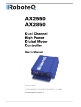
1
7
8
3
4
5
6
2
Specifications are subject to changes without prior notice
Measured in specific conditions
TECHNICAL SPECIFICATIONS
DESCRIPTION
1. main connectors
2. DIP-switch
3. loop sensitivity adjustment - loop 1
4. detection status LED - loop 1
Technology:
Tuning:
Detection mode:
Presence time:
Inductance range:
Frequency range:
Frequency steps:
Sensitivity (∆L/L):
Reaction time:
Setup time at power on:
Power supply:
Power consumption:
Temperature range:
Output:
Max. switching voltage:
Max. switching current:
Max. switching power:
Main connector:
LED indicators:
Protections:
Dimensions:
Weight:
Product compliance:
inductive loop
automatic
presence
1 min to infinity
20 µH to 1000 µH
20 kHz to 130 kHz
S-version: 4; D-version: 2
0.005% to 0.5%
S-version: 25 ms; D-version: 50 ms
S-version: 2 s; D-version: 6.5 s
24 VDC +/-20%
< 2 W
-30 °C to +70 °C (storage); -30 °C to +55 °C (operating)
optocoupler (S-version: 1x; D-version: 2x)
40 V DC
10 mA
100 mW
2x PC Board Connector MOLEX type KK series 3215, 5 entries
1x FCI 01-381 series (loop connection)
green LED: power; red LED: loop status
loop insulation transformer, zener diodes, gas discharge clamping
20 mm (H) x 50 mm (W) x 72.5 mm (D)
< 50 g
RED 2014/53/EU, RoHS 2 2011/65/EU
Inductive loop control PCB with optocoupler output
MATRIX PLUG-IN S24 C PC: for single loop (S-version)
MATRIX PLUG-IN D24 D PC: for double loop (D-version)
Please keep for further use
Designed for colour printing
ENGLISH
5. presence time adjustment
6. power LED
7. loop sensitivity adjustment - loop 2
(D-version only)
8. detection status LED - loop 2 (D-version only)

MIN MAX
0.5%
0.44%
0.34%
0.25%
0.18%
0.1%
0.005%
MIN
MAX
MIN MAX
0.5%
0.44%
0.34%
0.25%
0.18%
0.1%
0.005%
1
2
3
LOOP SENSITIVITY
Loops are mostly installed in a quadratic or rectangular form.
According to the loop size, the loop wire has to be turned a different
number of times in the slot.
Max. length: 100 m; max. cable cross-section: 1.5 mm
2
The table below shows the requested number of turns in a loop
according to the loop size (side ratio 3:1 = b:a).
LOOP INSTALLATION
WIRING
TIP!
See application note for
detailed instructions.
Circumference
4 - 5 m
5 - 6 m
6 - 15 m
Number of turns
5
4
3
Inductivity
180 - 200 µH
130 - 160 µH
140 - 150 µH
Loop 1 Loop 2 (D-version only)
MAX PRESENCE TIME
Max. duration of presence detection
POTENTIOMETER ADJUSTMENTS
1 min
10 min
1 h
2 h
5 h
20 h
infinity
CONNECTOR 1
PIN 1 GND
PIN 2 24 VDC
PIN 3 GND optocoupler
PIN 4 output 2 (D-version only)
PIN 5 output 1
CONNECTOR 2
PIN 1 not used
PIN 2 not used
PIN 3 not used
PIN 4 not used
PIN 5 not used
CONNECTOR 3
PIN 1 loop 1
PIN 2 loop 1
PIN 3 loop 2 (D-version only)
PIN 4 loop 2 (D-version only)
CONNECTOR 1 CONNECTOR 2
CONNECTOR 3
PIN 1 PIN 1
PIN 1

-
-
-
-
4
OUTPUT SIGNAL
LOOP FREQUENCY LOOP FREQUENCY NOT USED
ASB-FUNCTION
S-VERSION
Single loop
D-VERSION
Double loop
ON
OFF
FREQUENCY
LOOP 1
FREQUENCY
LOOP 2
NOT USED
ASB-FUNCTION
ON
OFF
After a oscillation frequency variation of more than 10 %, the sensor automatically launches a learning process.
Automatic sensitivity boost function (ASB)
The ASB function is recommended for detection of elevated vehicles such as
trucks, but also for all-terrain vehicles.
During detection, the sensor automatically multiplies the sensitivity set by the
potentiometer by 8. The sensitivity is limited to the maximum sensitivity and
returns to its initial value after detection.
DIP-SWITCH ADJUSTMENTS
TIP!
See application note for
more information.
LOOP 1
LOOP 2
OUTPUT 1
OUTPUT 2
MEDIUM
HIGH
HIGH
LOW
MEDIUM
LOW
ON
OFF
LOW
HIGH
LOW
HIGH
ON
OFF
high - 20%
high - 25%
high - 30%
FACTORY VALUES

1
1
1
1
1Hz
2Hz
1
BEA SA | LIEGE Science Park | ALLÉE DES NOISETIERS 5 - 4031 ANGLEUR [BELGIUM] | T +32 4 361 65 65 | F +32 4 361 28 58 | [email protected] | WWW.BEA-SENSORS.COM
TROUBLESHOOTING
LED-SIGNAL
Power
Loop detection status
Oscillation frequency
Troubleshooting
LED flashes
LED flashes
quickly
LED is off
During normal functioning, the red LED is ON as long as the loop detects a metal object.
On power on, the red LED displays the oscillation frequency of the loop measured by the sensor. If for example the LED
flashes 4x, the frequency lies between 40 kHz and 49 kHz.
There is no power supply.
Check power supply.
The loop detector
does not work.
The loop is shorted.
Check the loop cabling.
The loop detector
does not work.
The loop detector
does not work.
The oscillation frequency is
too low or the loop is open.
Adjust the frequency (DIP-switch 1 & 2)
or change the number of loop turns.
The loop LED is
functioning properly,
but no contact is
made.
Bad connection of the
output contacts.
Check connections.
The loop detector
does not work.
The oscillation frequency is
too high.
Adjust the frequency (DIP-switch 1 & 2)
or change the number of loop turns.
The manufacturer of the global system is responsible for carrying out a risk assessment and installing the device and the
global system in compliance with applicable national and international regulations and standards on safety. Other use of
the device is outside the permitted purpose and can not be guaranteed by the manufacturer. The manufacturer cannot
be held responsible for incorrect installations or inappropriate adjustments of the device.
SAFETY INSTRUCTIONS
The warranty is void if unauthorized
repairs are made or attempted by
unauthorized personnel.
Only trained and qualified
personnel may install and
setup the sensor.
Test the good functioning
of the installation before
leaving the premises.
©BEA | Original instructions | 47.0215 / V2 -08.18
BEA hereby declares that the MATRIX PLUG-IN is in conformity with the basic requirements and the
other relevant provisions of the directives RED 2014/53/EU, RoHS 2 2011/65/EU.
Only for EC countries: According the European Guideline 2012/19/EU for Waste Electrical and Electronic Equipment (WEEE)
/