Page is loading ...

MATRIX-4
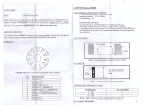
Sensitivity adjustment
LOOP A
DIGITAL INDUCTIVE LOOP SENSOR*
DESCRIPTION
DIP-switches
Presence time
adjustment
Push Button
Sensitivity adjustment
LOOP B
MATRIX-4-D only
Detection state LED
OUTPUT 2
Detection state LED
OUTPUT 1
Connection
LOOP A
Connection
LOOP B
Main connector
(86CP11)
TECHNICAL SPECIFICATIONS
-30 °C to +70 °C
-30 °C to +55 °C
2 relays, 0.5 @ 42 VAC on
resistive load
• 1 green LED: power
• 1 red LED: OUTPUT 1
• 1 red LED: OUTPUT 2
standard 11-pin round
connector 86CP11
2 contacts for each loop,
plug-in terminal for section
cable up to 2.5 mm²
77 mm (H) x 40 mm (W) x 75
mm (D)
< 200 gr
RED 2014/53/EU
EMC 2014/30/EU
Technology
Tuning
Detection mode
Presence time
Pulse time output
Inductance range
Frequency range
Frequency steps
Sensitivity (∆L/L)
Reaction time
Power supply
Mains frequency
Power consumption
Degree of protection
inductive loop
automatic
presence and motion
1 min to infinity (permanent presence)
in 8 steps
100 ms
40 µH to 470 µH
20 kHz to 130 kHz
2 for each loop
0.004% to 0.512% in 8 steps
33 ms without memory effect
140 ms with memory effect
12-24 AC/DC +10% - 5%
48 to 62 Hz
< 3 W
IP40
Storage temperature range
Operating temperature range
2 Output relays (free poten-
tial change-over contact)
LED indicators
Main connector
Loop connector
Dimensions
Weight
Product compliance
LOOPS INSTALLATION TIPS
1. CABLE SPECIFICATIONS FOR LOOP AND FEEDER
- 1.5 mm² cross section area
- Multi-strand cable
- Insulation material: PVC or Silicone
- For the feeder cable, the wire must be twisted at least 15 times by meter
- A foil screened cable is recommended for long feeder runs (earth at equipment end only)
- The feeder cable must be firmly fixed to avoid any false detection (max length: 100m)
- Waterproof cable junction box is required
Specifications are subject to changes without prior notice.
*Other use of the device is outside the permitted purpose and can not be guaranteed by the manufacturer.
ENGLISH
MATRIX-4-D
MATRIX-4-D only
MATRIX-4-S
Connection
LOOP A
This user’s guide is an informative document and
can not be seen as a commitment of result.

PIN 1
PIN 2
PIN 3
PIN 4
PIN 5
PIN 6
PIN 7
PIN 8
PIN 9
PIN 10
PIN 11
D = min. 1 m
D
4< 3 m²
33 - 5 m²
26 - 10 m²
NO (PIN 10 & 11)
NC (PIN 3 & 5)
2. DETERMINATION OF THE NUMBER OF LOOP TURNS
For example:
Loop A: if L = 2 m, Ea = 1 m and the number of turns = 4,
then the NA = 2 x 1 x 4 = 8 < 20
Loop B: if L = 2 m, Eb = 1 m and the number of turns = 4,
then the NA = 2 x 1 x 4 = 8 < 20
WARNING:
For conformity reasons, in any situation, the antenna factor defined as the loop surface multiplied by the number of turns should no exceed NA = 20
Rem: Avoid large loops or long feeder
(max 100 m), the sensitivity will be
affected.
3. SLOT DEPTH
Loop sealant
30 - 50 mm depending on cable turns number
Clean and dry slots prior to inserting cable
Rem: Make sure no metalic objects are present in proximity of the loops
WIRING
Power supply
Power supply
Relay 2 (NC)
Relay 2 (COM)
Relay 1 (NC)
Relay 1 (COM)
Not used
Not used
Not used
Relay 1 (NO)
Relay 2 (NO)
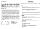
RELAY CONFIGURATIONS - PASSIVE MODE
NO DETECTIONNO POWER DETECTION
ADJUSTMENTS
1. THE CONFIGURATIONS (see table on p.4 - MATRIX-4-D only)
Configuration # 1: Independent mode
Configuration # 2: Combined mode
2. THE PUSH BUTTON
• Short push on the push button (max. 2.5 seconds): confirmation of a setting by rotary or DIP-switch (only 1 - 6). If a
switch value is changed without a manual confirmation by the PB, the green LED flashes, but the sensor continues to
work with its prior values.
• Long push on the push button (from 2.5 to 10 seconds): launching of learn mode after changing a loop frequency or
after any modification concerning the loop installation. This function launches a similar self tuning as during the power
on sequence.
The push button has two functions:
Rem: Make sure the distance D still allows any
object to be detected on both loops at the
same time with the directional mode.
Feeder cable
LOOP A
LOOP B
Feeder cable
LOOP A
LOOP B
Number of loop turnsSurface

0
1
2
3
4
5
6
7
0.512 %
0.256 %
0.128 %
0.064 %
0.032 %
0.016 %
0.008 %
0.004 %
0.512 %
0.256 %
0.128 %
0.064 %
0.060 %
0.060 %
0.060 %
0.060 %
0
1
2
3
4
5
6
7
DIP # 1
DIP # 2
DIP # 3
DIP # 4
DIP # 5
DIP # 6
DIP # 7&8
DIP # 9&10
3. ROTARY SWITCHES
• A rotary switch for adjustment of the sensitivity for the loop A.
• A rotary switch for adjustment of the sensitivity for the loop B (MATRIX-4-D only).
• A rotary switch for adjustment of the presence time adjustment: from 1 min to infinity
Memory effect
OFF
Memory effect
ON
1 min
5 min
10 min
1 hour
2 hours
5 hours
20 hours
infinity
PRESENCE TIME
ADJUSTMENT
SENSITIVITY
4. DIP SWITCHES
After each dip switch change, confirm the setting with a short push on the push button.
Independent or combined mode (see configuration table on p.4 - MATRIX-4-D only)
Automatic Sensitivity Boost - ASB (recommended for better trucks detection):
during a detection, the sensitivity increases automatically to 8 times the present sensitivity given by the
sensitivity rotary switch adjustment. It is limited to the maximum sensitivity (∆f = 0.004 %)
It goes back to the preset value after detection stops.
Relay 1 function: presence, pulse or directional pulse (see configuration table on p.4).
Relay 2 function: presence, pulse or directional pulse (see configuration table on p.4).
Relays 1 and 2 Pulse type (entry / exit).
Memory effect: the sensor keeps in memory the output states recorded just before a power cut.
Only functional if ASB is set OFF on DS2.
Loop A Oscillator frequency
These two switches are used to adjust the frequency of the loop oscillator A to avoid any
intermodulation with other loop installed in the field.
DIP # 7
DIP # 8
Loop A oscillator frequency
(in %)
OFF OFF 0 %
OFF ON -13 %
ON OFF -23 %
ON ON -30 %
Loop B Oscillator frequency (MATRIX-4-D only)
These two switches are used to adjust the frequency of the loop oscillator B to avoid any
intermodulation with other loop installed in the field.
DIP # 9
DIP # 10
Loop B oscillator frequency
(in %)
OFF OFF 0 %
OFF ON -13 %
ON OFF -23 %
ON ON -30 %
After rotary switch change, confirm the setting with a short push on the push button.

OFF ONDS # 2 OFF ON
DS # 3
DS # 4
DS # 5
DS # 6 OFF ON OFF ON
BEA SA | LIEGE Science Park | ALLÉE DES NOISETIERS 5 - 4031 ANGLEUR [BELGIUM] | T +32 4 361 65 65 | F +32 4 361 28 58 | [email protected] | WWW.BEA-SENSORS.COM
OFF <= => ON OFF <= => ON
5. CONFIGURATIONS
Independent mode - DS # 1 (OFF <=)
MATRIX-4-S and MATRIX-4-D
Combined mode - DS # 1 (=> ON)
MATRIX-4-D only
ASB mode
Rel 1 : Detection mode
Rel 2 : Detection mode
Presence Loop A Pulse Loop A
Presence Loop B Pulse Loop B Presence (A or B)
Opposite combined**
Rel 1&2 : Pulse mode
Memory effect*
* Memory Effect Mode: Only functional if ASB is set OFF by DS2.
** See sticker on the product for more details.
*** If both relays are in pulse mode, DS5 setting applies to relay 1. Pulse of relay 2 is the opposite setting. (MATRIX-4-S only)
LED SIGNAL
FAILURE MODES
1. When a loop fault is detected, the corresponding relay of the loop is activated to prevent an accident as long as
the fault is not solved. This error is stored during the line voltage OFF/ON procedure only if the memory effect is
functional.
2. If the frequency oscillator of the loop (A or B) drifts out of its limits (+/- 10 %), the corresponding relay remains in a
detection state and the red LED flashes at 5 Hz frequency. When the frequency oscillator goes back to correct values,
the MATRIX works normally again.
3. If a switch value is changed without manual validation by the PB, the green LED flashes at 5 Hz to signal an error. This
information is stored to avoid an automatic validation after a power reset.
4. On power ON, if the inductance of the loop is out of the predefined range (40 µH to 470 µH) the LED gives an error
signal status following to the table hereafter. The loop remains in this state until the problem is solved.
5. If an internal failure of the µP is detected during the normal operation the 2 relays are activated, the green LED is
turned off and the 2 red LED status is undertermined. To restart the µP, you can launch a manual setup by pressing the
PB at least 2.5 sec.
Loop Default
The inductance is > 470 µH
The inductance is < 40 µH
Loop oscillator failed
LED display
LED flashes 3x / 2 sec
LED flashes 4x / 1 sec
LED flashes 1x / 2sec
©BEA | Original instructions | 42.7075 / V4 - 07.18
Hereby, BEA declares that this radio equipment is in compliance with Directive 2014/53/EU (RED) and Directive
2011/65/EU (RoHS). The full text of the EU declaration of conformity is available on our website.
This product should be disposed of separately from unsorted municipal waste
Entry*** Exit Entry Exit
B -> AA -> B
The green LED indicates that the sensor is powered.
ON: correct line voltage
OFF: internal problem or power line voltage is too low
The green LED flashes when a switch is changed without validation by the PB.
The red LED indicates the corresponding output detection state. Each LED is assigned to one output.
When the voltage line is applied, the sensor measures the oscillation frequency of each loop.
The result of this measurement is displayed on time by using the corresponding red LED.
If a detection occurs during a frequency display procedure, the frequency display is cancelled and
the relay status is displayed by the red LED.
GREEN LED
RED LED
/
![Eberle DesignDeflectometer Inductive Loop Monitor [LMD602, LMD602T, LMD604,LMD604T]](http://vs1.manuzoid.com/store/data/001476625_2-352a61b560d4fc181793a55d495056b5-160x210.png)


