Page is loading ...

75.5094.03 20130710 Page 1 of 5
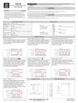
The MATRIX is a Digital Inductive Loop Detector used for the detection of vehicular traffic. The MATRIX is the ideal solution for
parking barrier control, motorized gates and doors, vehicle access control and industrial control systems.
The MATRIX is a high performance single or dual-channel vehicle detector packaged in a compact housing. The connection is
made with a standard industrial 11-pin octal (round) socket.
MATRIX2-S110 CUSTOM: Single loop detector with 110 to 120 V AC power supply.
MATRIX2-S12-24 CUSTOM: Single loop detector with 12-24V AC/DC power supply.
Technology : Inductive loop
Tuning : automatic
Detection mode : presence
Presence time : 1 min to infinity (permanent
presence) with 250 steps.
Pulse time output : 100 ms or 500 ms
Inductance range : 20 µH to 1000 µH
Frequency range : 20 kHz to 130 kHz
Frequency steps : 4 for single loop
2 for dual loop (for each loop)
Sensitivity (L/L) : 0.005% to 0.5% with 250 steps
Reaction time : 25ms for single loop
50ms for dual loop(each channel)
Setup time at power on : 8 s max by channel
Setup time after configuration : 2s max by channel
Power supply (depending on model) :
12-24 AC/DC 10%
230VAC 10 %
115VAC 10 %
Power Frequency : 48 to 62 Hz
Power Consumption : < 2.5 W
Temperature range : -22F to 158F
[-30°C to +70°C]
Degree of protection : IP40
2 Output relays (free potential change-over contact) :
Max contact voltage : 230 VAC ;
Max contact current : 5A (resistive).
LED indicators :
1 green LED : power ;
1 red LED : Loop status 1 ;
1 red LED : Loop status 2.
Protections :
loop insulation transformer ;
Zener diodes ;
gas discharge clamping.
Connection :
Standard 11-pin round connector 86CP11
Dimensions : 3 in (H) x 1.5 in (W) x 3 in (D)
[77mm (H) x 40mm(W) x 75mm(D)]
Weight :7 ounces [< 200g]
Product compliance :
R&TTE 1999/5/EC
EMC 89/336/EE
Shut off all power before attempting any wiring procedures
Maintain a clean & safe environment.
Constantly be aware of traffic around the door or gate area.
Always suspend traffic through the doorway or gate area when performing testing that may result in
unexpected reactions by the door or gate.
Always check placement of all wiring and components before powering up to insure that moving parts will not
catch any wires and cause damage to equipment.
APPLICATION
TECHNICAL
SPECIFICATIONS
DESCRIPTION
OF THE
SENSOR
1.5 in
3 in
3 in
SAFETY
PRECAUTIONS
!
We open up New Horizons
USERS GUIDE
MATRIX2
DIGITAL INDUCTIVE LOOP SENSORS

Page 2 of 5
75.5094.03 20130710
1 ¼ - 2” (30 – 50mm)
depending on the cable
turns number
C
l
e
a
n
a
n
d
d
r
y
s
l
o
t
s
p
r
i
o
r
t
o
i
n
s
e
r
t
i
n
g
c
a
b
l
e
Loop sealant
Ground
level
WARNING:
For conformity reasons, in any installation,
the loop surface multiplied by the number of
turns should not exceed 215 (for square
feet); 20 (for square meters)
A . CABLE SPECIFICATIONS FOR LOOP AND FEEDER
16 AWG (1.5mm²) cross section area ;
Multi-strand cable ;
Insulation material : PVC or Silicone ;
For the feeder cable, the wire must be twisted at least 15 times per yard for each cable.
Feeder for long runs used for foil screened cable is recommended (earth at equipment end only)
The feeder cable must be firmly fixed to avoid any false detection (max length: 330 feet (100 m)).
Waterproof cable junction box is required.
B. LOOP GEOMETRY
Avoid large loops or long feeder cables [max 330 feet (100
m)]. Longer runs may affect sensitivity of loop.
C. DETERMINATION OF THE NUMBER OF LOOP TURNS
Measure the length (L) and width (Ea) of one loop. Multiply these numbers together to determine the
loop surface area. See above drawing.
For example, if L=10 ft, Ea= 3 ft, then the area = 30 ft
2
; 4 loop turns are recommended.
or if L=2m, Ea=1m, then the area = 2 m
2
; 4 loop turns are recommended.
Recommended values for the turns:
D. SLOT DEPTH
Pin 1 : Power Supply
Pin 2 : Power Supply
Pin 3 : Relay B (NO)
Pin 4 : Not Required
Pin 5 : Presence (Relay A - COM)
Pin 6 : Presence (Relay A – NO)
Pin 7 : Loop
Pin 8 : Loop common and connect to ground
Pin 9 : Relay B (COM)
Pin 10 : Presence (Relay A - NC)
Pin 11 : Relay B (NC)
UL Requirement: Shall be used with suitable UL Recognized SWIV2 Relay Socket.
Area
Number of turns
<32 ft²
<3 m²
4
32 – 54 ft²
3 – 5 m²
3
65 – 108 ft²
6 – 10 m²
2
WIRING
LOOP
INSTALLATION
TIPS
L
Ea
Eb
!
WARNING:
Pin #8 must be connected to the loop and to ground
!

Page 3 of 5
75.5094.03 20130710
CONFIGURATION
POTENTIOMETERS
A potentiometer for adjustment of the maximum duration of a
presence detection : from 1 min to infinity ; (see Fig. 1)
A potentiometer for adjustment of the linear sensitivity (f) for the
loop A : from 0.005% to 0.5 % ; (see Fig. 2)
A potentiometer for adjustment of the linear sensitivity (f) for the
loop B : from 0.005% to 0.5 %. (see Fig. 2)
A 10 position dip switch is located on the front of the Matrix single detector. Dip switch 3, 5, 6, 7, and 8 configure the relay, while
dip switch 9 controls the duration of the pulse when the Matrix is configured for pulse operation, (as opposed to presence).
Configurations are as follows:
Dip Switch 3:
OFF= FAIL-SECURE MODE Relay is NOT energized when power is applied. Relay is energized upon detection only. In this
mode, the N.O. circuit is open, and the N.C. circuit is closed. Thus, if a closed circuit is required upon detection, one must use
the N.O. and COM terminals since they would close upon detection. When the Matrix is NOT powered, it is in the same state as
it would be for non-detection.
ON = FAIL-SAFE MODE Relay is energized as soon as power is applied, and de-energizes upon detection or power loss. In
this mode, upon powering the detector, the N.O. circuit becomes closed, and the N.C. circuit becomes open. Thus, if a closed
circuit is required upon detection, one must use the N.C. and COM terminals, since they would now be OPEN during non-
detection, and would close upon detection. When the Matrix is NOT powered, it is in the same state as it would be for detection.
Detection Status
Fail-Secure Mode
(Relay is not energized upon power-on)
Fail-Safe Mode
(Relay becomes energized upon power-on)
No Detection
The COM and N.O. terminals are OPEN.
COM and N.C. terminals are CLOSED.
The relay is de-energized.
The COM and N.O. terminals are CLOSED.
COM and N.C. terminals are OPEN.
The relay is energized.
Detection
The COM and N.O. terminals are CLOSED.
COM and N.C. terminals are OPEN.
The relay is energized.
The COM and N.O. terminals are OPEN.
COM and N.C. terminals are CLOSED.
The relay is de-energized.
Upon Power Loss
The COM and N.O. terminals are OPEN.
COM and N.C. terminals are CLOSED
The relay is de-energized.
The COM and N.O. terminals are OPEN.
COM and N.C. terminals are CLOSED.
The relay is de-energized.
Single loop Configurations
OFF
ON
DS#1
See next table
Frequency Settings
DS#2
DS#3
Active mode
Passive mode
DS#4
ASB OFF
ASB ON
DS#5
Relay A :
Presence on loop A
Relay A :
Pulse on loop
DS#6
Relay A :
Pulse on loop A
entry
Relay A :
Pulse on loop A
exit
DS#7
Relay B :
Presence on loop A
Relay B :
Pulse on loop A
DS#8
Relay B :
Pulse on loop A
entry
Relay B :
Pulse on loop A
exit
DS#9
100 ms
500 ms
DS#10
Not used
Not used
PROGRAMMING
M
i
n
M
a
x
1
m
i
n
1
0
m
i
n
1
H
2
H
5
H
2
0
H
I
n
f
i
n
i
t
y
P
r
e
s
e
n
c
e
t
i
m
e
M
i
n
M
a
x
0
.
5
%
0
.
4
4
%
0
.
3
4
%
0
.
2
5
%
0
.
1
8
%
0
.
1
%
0
.
0
0
5
%
S
e
n
s
i
t
i
v
i
t
y
FIG. 2
FIG. 1
Same
Same
DIPSWITCH
SETTINGS

Page 4 of 5
75.5094.03 20130710
FREQUENCY
After each dip switch change the sensor launches a learning process. Thus, when changing dipswitch settings, insure that the
loop area is all clear. By default, all dipswitches are set to OFF.
#
OFF
ON
REMARKS
1
See Frequency Adjustments Chart
2
See Frequency Adjustments Chart
3
Fail-Secure
Fail-Safe
Output Relay Configuration
4
ASB OFF
ASB ON
Automatic Sensitivity Boost (ASB option) [recommended for improved
truck detection] :
During a detection, the sensitivity increases automatically to 8 times the
preset sensitivity given by the sensitivity potentiometer adjustment. It is
limited to the maximum sensitivity (f = 0.005%). It goes back to the preset
value after detection stops.
5
Relay A
Presence
Relay A
Pulse
In presence mode, Relay A will hold a changed state as long as there is
detection at Loop A. A pulse mode will result in a momentary pulse upon
entering the loop or exiting the loop, according to dip switch 6.
6
Pulse On
Entry
Pulse On
Exit
ON = Relay A will pulse once upon detection at Loop A
OFF = Relay A will pulse once upon loss of detection at Loop A
7
Relay B
Presence
Relay B
Pulse
In presence mode, Relay B will hold a changed state as long as there is
detection at Loop A. A pulse mode will result in a momentary pulse upon
entering the loop or exiting the loop, according to dip switch 8.
8
Pulse On
Entry
Pulse On
Exit
ON = Relay B will pulse once upon detection at Loop A
OFF = Relay B will pulse once upon loss of detection at Loop A
9
100ms
500ms
Pulse Duration: The amount of time the relay will hold a changed state
when operating in a pulse mode
10
Single
Dual
Dual loop mode : independent or combined AB (not used with single
loop)
Green LED shows when the module is powered;
Red LEDs gives:
the corresponding loop detection state in normal situation;
the value of the oscillation frequency measurement or an error message on power ON.
In NORMAL SITUATION the red LED stays ON as long as the loop detects any object.
On POWER ON, the sensor measures the oscillation frequency of each loop. The result of this measurement is
displayed using the corresponding red LED. The number of flashes indicates the tens value of the frequency. For
example 4 short flashes correspond to a frequency between 40 kHz and 49 kHz. After this message the LED
goes back to normal display.
If the loop oscillation frequency falls outside the limits (20 kHz to 130 kHz) the red LED displays an error
message and the sensor activates the corresponding relay. The blinking frequency shows the type of error
according to the next table. The sensor will stay in error mode until the error is cleared and the frequency goes to
the right range.
Remark : The sensor launches automatically a learning process if the oscillation frequency varies more than 10%
in comparison with the measurement value.
Loop Frequency Error
LED Display
Oscillation frequency too LOW or loop opened
LED blinking at 1Hz
Oscillation frequency too HIGH
LED blinking faster at 2 Hz
Loop shorted or no oscillation
LED blinking slower at 0.5 Hz
Frequency adjustment for loop A for single loop detector
Dip Switch #1
Dip Switch #2
Loop frequency
OFF
OFF
High
ON
OFF
Mid High [High –20%]
OFF
ON
Mid Low [High – 25%]
ON
ON
Low [High – 30%]
LED SIGNAL
DIPSWITCH
SETTINGS
(CON’T)

Page 5 of 5
75.5094.03 20130710
SYMPTOM
PROBABLE CAUSE
CORRECTIVE ACTION
The loop detector will not work.
The green LED is off.
There is no power supply to the
loop detector.
Check power supply.
The loop detector will not work.
The red LED is flashing slowly
(0.5 Hz).
The corresponding loop is
shorted.
Check the loop cable.
The loop detector will not work.
The red LED blinks at either 1Hz
or 2Hz.
The frequency of oscillation falls
outside the allowed range.
Adjust frequency with dip
switches
or change loop turns.
The loop LED is detecting properly
but the contact is not made.
Bad connection of the relay
contacts.
Check relay connections.
Dip switches 5 to 8 are not
responding properly.
Their function varies according to
dip switch #10 setting.
Check the appropriate loop
mode required and adjust
dip switch #10.
If after troubleshooting a problem, a satisfactory solution cannot be achieved, please call B.E.A., Inc.
for further assistance during Eastern Standard Time at 1-800-523-2462 from 8am - 5pm.
For after-hours, call East Coast: 1-866-836-1863 / Mid-West: 1-888-308-8843
West Coast: 1-888-419-2564. DO NOT leave any problem unresolved. If you must wait for the following workday to call
B.E.A., leave the door inoperable until satisfactory repairs can be made.
NEVER sacrifice the safe operation of the automatic door or gate for an incomplete solution.
Web: www.beasensors.com
TROUBLE -
SHOOTING
COMPANY
CONTACT
/