Page is loading ...

UG367: Si823Hx-EVB User's Guide
The Si823Hx isolated gate drivers are ideal for driving power switches used in a wide
variety of power supply, inverter, and motor control applications, offering longer service
life and dramatically higher reliability compared to opto-coupled gate drivers. The
Si823Hx isolated gate drivers utilize Silicon Laboratories' proprietary silicon isolation
technology supporting up to 5 kVRMS withstand voltage per UL1577 and VDE0884.
This technology enables industry-leading common-mode transient immunity (CMTI),
tight timing specifications, reduced variation with temperature and age, better part-to-
part matching, and extremely high reliability. It also offers unique features, such as sep-
arate pull-up/down outputs, driver shutdown on UVLO fault, and precise dead time pro-
grammability. Driver outputs can be grounded to the same or separate grounds or con-
nected to a positive or negative voltage. The TTL level compatible inputs with 800 mV
hysteresis are available in individual control input (Si823H1/2/3/5/6/7 and Si82520) or
PWM input (Si823H4/8) configurations. High integration, low propagation delay, small in-
stalled size, flexibility, and cost-effectiveness make the family ideal for a wide range of
isolated MOSFET/IGBT/SiC/GaN gate drive applications.
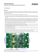
The Si823Hx evaluation board allows designers to evaluate Silicon Lab's Si823Hx family
of high CMTI performance ISOdrivers. The boards come populated with either the
Si823H2, Si82520, or two Si823H9 version of the family. The board includes screw ter-
minals for quick evaluation of the devices’ key parameters and includes test points on
each devices’ pins to accommodate direct connection to the designer’s end system. For
more ISOdriver information, visit Silicon Labs web site at www.silabs.com/isolation. The
product data sheet and numerous application notes can be referenced to help facilitate
designs.
KIT CONTENTS
• Si823Hx-based evaluation board
(Si823Hx-EVB) populated in one of the
following configurations:
•
1 - Si823H2, 2-input, 4 A, 5 kVrms High-
Side/Low-Side ISOdriver
• 1 - Si82520, 2-input, High Input Voltage,
4 A, 5 kVrms High-Side/Low-Side
ISOdriver
• 2 - Si823H9 1-input, 4 A, 5 kVrms Single
Channel ISOdrivers
silabs.com | Building a more connected world. Rev. 0.1

1. Required Equipment
The following equipment is required to demonstrate the evaluation board:
•
One signal generator
• One dual dc power supply: 0–5 V and 0–15 V (or two single supplies)
• 1 oscilloscope (at least two channels)
• Assorted cables, leads and probes as necessary to connect equipment to EVB
• Si823Hx evaluation board (board under test)
• Si823Hx evaluation board user’s guide (this document)
1.1 DC Supply Configuration
1. Set one supply to output 5 VDC.
2. Turn OFF the supply and connect the positive lead to VDDI (J1 pin1 or TP1).
3. Connect the negative lead to GNDI (J3 or TP3).
4. Turn ON the dc power supply.
5. Ensure that LED D1 turns on.
6. Ensure that the current draw is less than 25 mA. If it is larger, this indicates that either the board or Si823Hx has been damaged or
the supply is connected backwards.
7. Set the other supply to output 15 VDC.
8. Turn OFF the supply and connect the positive lead to VDDA (J2 or TP2).
9. Connect the negative lead to GNDA (J4 or TP4).
10. Turn ON the supply.
11. Ensure that LED D2 turns on.
12. Ensure that the current draw is less than 100 mA. If it is larger, this indicates that either the board or Si823Hx has been damaged
or the supply is connected backwards.
1.2 Function Generator
1. Turn ON the function generator with the output disabled.
2. Adjust its output to provide a 500 kHz, 0 to 5 V peak square wave (50 percent duty cycle) to its output.
3. Connect the output of the generator to VIA (TP5, ground on TP6).
4. Ensure a shunt is placed on TP3 between pins 2 and 3 (connects VIB to GND).
a. If the board being tested is Si823H2 or Si823H9, ensure a shunt is placed on JP4 between pins 1 and 2 to enable the device.
b. If the board being tested is an Si82520, ensure that the shunt on JP4 is between pins 2 and 3 to enable the device.
5. Enable the output of the waveform generator.
UG367: Si823Hx-EVB User's Guide
Required Equipment
silabs.com | Building a more connected world. Rev. 0.1 | 2

1.3 Oscilloscope Setup
To set up the oscilloscope, perform the following steps:
1.
Set the scope to Trigger on CH1 and adjust the trigger level to approximately 2 V.
2. Set CH1 to 2 V per division and CH2 to 5 V per division
3. Adjust the seconds/division setting to 500 ns/division
4. Connect the scope channel 1 probe to VIA (TP5). Ground the probe to GNDI (TP6)
5. Connect Channel 2 probe to VOA (J5 pin 4 or TP11). Ground the probe to GNDA (J5 pin 3 or TP12)
6. Adjust the vertical position of each channel to properly view each channel as shown in the figure below
A 500 kHz square wave should display on Channel 1 of the scope for the input and a 15 V version should display on Channel 2, as
shown in the following figure.
Figure 1.1. 500 kHz Square Wave
1.4 Repeat for Second Channel
1.
Disable the function generator output.
2. Turn OFF the 15 V supply.
3. Disconnect 15 V supply from VDDA/GNDA.
4. Connect the 15 V supply to VDDB (J6 or TP20) and GNDB (J7 or TP21).
5. Move the Channel 2 scope probe to VOB (J5 pin 2 or TP18) and GNDB (J5 pin 1 or TP17).
6. Remove the shunt on JP3.
7. Move the function generator to VIB (TP9) and GNDI (TP10).
8. Place shunt on JP1 between Pins 2 and 3 (connects VIA to GNDI).
9. Turn ON the dc supply.
10. Ensure that LED D6 turns on.
11. Ensure that the current draw is less than 100 mA. If it is larger, this indicates that either the board or Si823Hx has been damaged
or the supply is connected backwards.
12. Enable the function generator output.
13. The scope display should show both the input and output waveforms as before.
UG367: Si823Hx-EVB User's Guide
Required Equipment
silabs.com | Building a more connected world. Rev. 0.1 | 3

2. Built-In Options
The Si823Hx EVB comes from the factory configured to provide VOA, GNDA, VOB and GNDB signals out to the connector J5. This
allows the evaluation of the Si823Hx drivers on their own. However, the board provides pads in which the customer can place compo-
nents to build a half bridge for the Si823Hx to drive. This allows the customer to evaluate the Si823Hx driver in a manner that is closer
to a real application.
To configure the board for a half bridge circuit, the following components must be removed:
• R3
• R9
• R11
Also, components for the following reference designators must be added:
• R7
• U3 or U4
• U5 or U6
The positions for U3, U4 provide an option for the customer to place a FET that is either a TO-220 package or a D-PAK package for the
high side of the half-bridge. These two components are wired in parallel. They should not both be populated at the same time. The
same is true for U5 and U6 for the low side device. The customer is free to place virtually any component in those positions to evaluate
the Si823Hx driver in a circuit that resembles their intended application.
In addition to these options, there is a footprint for D4 and D5 as well as R4 and R8. This allows the customer to optimize the turn on
and turn off currents for the FET’s if they choose to do so. It should be noted that these diodes do not exist on the Si823H9-EVB. The
Si823H9 driver provides separate pull-up and pull-down outputs making it unnecessary to use a diode. The resistors used for this pur-
pose on the Si823H9-EVB are R4, R5, R8 and R10.
Furthermore, resistors R6 and R13 are footprints provided for the customer to add pull down resistors to turn off each FET should
something prevent the VOA/VOB outputs from pulling the gate circuits low.
If these options are implemented, the pinout of J5 changes slightly. Pin 1 remains connected to GNDB and would be used for the half-
bridge supply ground. Pin 2 becomes the output of the half-bridge. Pin 3 is no longer connected to anything. Pin 4 becomes the half-
bridge positive supply.
Another option on the evaluation board is the setting of JP2. If a shunt is connected between pins 2 and 3 of JP2, the VDDA pin of the
Si823Hx is connected to J2. This allows the customer to evaluate the Si823Hx driver with independent supplies. If a shunt is connected
between pins 1 and 2 of JP2, then the VDDA pin is connected to diode D3 which is then connected to VDDB. This creates a boot strap
supply for the A driver. In this configuration, capacitor C3 becomes the boot strap capacitor. It may be necessary to modify the value of
C3 to optimize the performance of the boot strap supply. Please see our boot strap calculation tool online at https://www.silabs.com/
tools/Pages/bootstrap-calculator.aspx.
Note: The Si823H9 and Si82520 evaluation boards are populated with dual drivers that have a high side/low side (HS/LS) operation.
This means that if both VIA and VIB inputs are driven high, the device’s overlap protection will force both VOA and VOB to a low state.
However, the Si823H9-EVB is built with two single channel drivers. This means there is no overlap protection. If the customer populates
the half-bridge components, they must make sure that both inputs are never driven high at the same time. Doing so will cause both FET
devices to turn on at the same time and short circuit the bridge supply. This will almost certainly damage the FET devices and likely
damage the Si823H9 devices as well.
UG367: Si823Hx-EVB User's Guide
Built-In Options
silabs.com | Building a more connected world. Rev. 0.1 | 4

3. Evaluation Board Schematics
Figure 3.1. Si823H2 Evaluation Board Schematic
UG367: Si823Hx-EVB User's Guide
Evaluation Board Schematics
silabs.com | Building a more connected world. Rev. 0.1 | 5

Figure 3.2. Si82520 Evaluation Board Schematic
Figure 3.3. Si823H9 Evaluation Board Schematic
UG367: Si823Hx-EVB User's Guide
Evaluation Board Schematics
silabs.com | Building a more connected world. Rev. 0.1 | 6

4. Evaluation Board Layouts
4.1 Si823H2-520 Layouts
Figure 4.1. Si823H2-520 Primary Silk
UG367: Si823Hx-EVB User's Guide
Evaluation Board Layouts
silabs.com | Building a more connected world. Rev. 0.1 | 7

Figure 4.2. Si823H2-520 Primary Side
UG367: Si823Hx-EVB User's Guide
Evaluation Board Layouts
silabs.com | Building a more connected world. Rev. 0.1 | 8

Figure 4.3. Si823H2-520 Ground
UG367: Si823Hx-EVB User's Guide
Evaluation Board Layouts
silabs.com | Building a more connected world. Rev. 0.1 | 9

Figure 4.4. Si823H2-520 VDD
UG367: Si823Hx-EVB User's Guide
Evaluation Board Layouts
silabs.com | Building a more connected world. Rev. 0.1 | 10

Figure 4.5. Si823H2-520 Secondary Side
UG367: Si823Hx-EVB User's Guide
Evaluation Board Layouts
silabs.com | Building a more connected world. Rev. 0.1 | 11

Figure 4.6. Si823H2-520 Secondary Silk
UG367: Si823Hx-EVB User's Guide
Evaluation Board Layouts
silabs.com | Building a more connected world. Rev. 0.1 | 12

4.2 Si823H9 Layouts
Figure 4.7. Si823H9 Primary Silk
UG367: Si823Hx-EVB User's Guide
Evaluation Board Layouts
silabs.com | Building a more connected world. Rev. 0.1 | 13

Figure 4.8. Si823H9 Primary Side
UG367: Si823Hx-EVB User's Guide
Evaluation Board Layouts
silabs.com | Building a more connected world. Rev. 0.1 | 14

Figure 4.9. Si823H9 Ground
UG367: Si823Hx-EVB User's Guide
Evaluation Board Layouts
silabs.com | Building a more connected world. Rev. 0.1 | 15

Figure 4.10. Si823H9 VDD
UG367: Si823Hx-EVB User's Guide
Evaluation Board Layouts
silabs.com | Building a more connected world. Rev. 0.1 | 16

Figure 4.11. Si823H9 Secondary Side
UG367: Si823Hx-EVB User's Guide
Evaluation Board Layouts
silabs.com | Building a more connected world. Rev. 0.1 | 17

Figure 4.12. Si823H9 Secondary Silk
UG367: Si823Hx-EVB User's Guide
Evaluation Board Layouts
silabs.com | Building a more connected world. Rev. 0.1 | 18

http://www.silabs.com
Silicon Laboratories Inc.
400 West Cesar Chavez
Austin, TX 78701
USA
Smart.
Connected.
Energy-Friendly.
Products
www.silabs.com/products
Quality
www.silabs.com/quality
Support and Community
community.silabs.com
Disclaimer
Silicon Labs intends to provide customers with the latest, accurate, and in-depth documentation of all peripherals and modules available for system and software implementers using or
intending to use the Silicon Labs products. Characterization data, available modules and peripherals, memory sizes and memory addresses refer to each specific device, and "Typical"
parameters provided can and do vary in different applications. Application examples described herein are for illustrative purposes only. Silicon Labs reserves the right to make changes
without further notice and limitation to product information, specifications, and descriptions herein, and does not give warranties as to the accuracy or completeness of the included
information. Silicon Labs shall have no liability for the consequences of use of the information supplied herein. This document does not imply or express copyright licenses granted
hereunder to design or fabricate any integrated circuits. The products are not designed or authorized to be used within any Life Support System without the specific written consent of
Silicon Labs. A "Life Support System" is any product or system intended to support or sustain life and/or health, which, if it fails, can be reasonably expected to result in significant
personal injury or death. Silicon Labs products are not designed or authorized for military applications. Silicon Labs products shall under no circumstances be used in weapons of mass
destruction including (but not limited to) nuclear, biological or chemical weapons, or missiles capable of delivering such weapons.
Trademark Information
Silicon Laboratories Inc.® , Silicon Laboratories®, Silicon Labs®, SiLabs® and the Silicon Labs logo®, Bluegiga®, Bluegiga Logo®, Clockbuilder®, CMEMS®, DSPLL®, EFM®,
EFM32®, EFR, Ember®, Energy Micro, Energy Micro logo and combinations thereof, "the world’s most energy friendly microcontrollers", Ember®, EZLink®, EZRadio®, EZRadioPRO®,
Gecko®, ISOmodem®, Micrium, Precision32®, ProSLIC®, Simplicity Studio®, SiPHY®, Telegesis, the Telegesis Logo®, USBXpress®, Zentri, Z-Wave and others are trademarks or
registered trademarks of Silicon Labs. ARM, CORTEX, Cortex-M3 and THUMB are trademarks or registered trademarks of ARM Holdings. Keil is a registered trademark of ARM Limited.
All other products or brand names mentioned herein are trademarks of their respective holders.
/