Page is loading ...

WARNING:
If the information in these instructions are not followed exactly,
a fi re or explosion may result causing property damage,
personal injury or loss of life.
FOR YOUR SAFETY
Do not store or use gasoline or other fl ammable vapors and
liquids in the vicinity of this or any other appliance.
Installation and service must be performed by a qualifi ed
installer, service agency or the gas supplier.
FOR YOUR SAFETY
What to do if you smell gas:
Do not try to light any appliance
Do not touch any electrical switch:
do not use any phone in your
building.
Immediately call your gas supplier
from a neighbour's phone. Follow
the gas supplier's instructions.
If you cannot reach your gas
supplier, call the fi re department.
FPI FIREPLACE PRODUCTS INTERNATIONAL LTD. 6988 Venture St., Delta, BC Canada, V4G 1H4
919-088a
01/17/14
Owners &
Installation Manual
Tested by:
Installer: Please complete the details on the back cover
and leave this manual with the homeowner.
Homeowner: Please keep these instructions for future reference.
MODELS: L965E-NG L965E-LP HZ965E-NG HZ965E-LP
www.regency-fi re.com
Regency L965E / HZ965E
Gas Fireplace
Liberty L965E
Horizon HZ965E

FOR SAFE INSTALLATION AND OPERATION OF YOUR “Regency” HEATER,
PLEASE CAREFULLY READ THE FOLLOWING INFORMATION:
• All Regency gas-fi red appliances must be installed
in accordance with their instructions. Carefully read all
the instructions in this manual fi rst. Consult the building
authority having jurisdiction to determine the need for a
permit prior to commencing the installation.
• NOTE: Failure to follow these instructions could
cause a malfunction of the fi replace, which could result in
death, serious bodily injury, and/or property damage.
• Failure to follow these instructions may also void your
fi re insurance and/or warranty.
GENERAL
• Installation and repair should be done by a qualifi ed
service person. The appliance should be inspected
before the fi rst use and, at least, annually by a qualifi ed
service person. More frequent cleaning may be required
due to excessive lint from carpeting, bedding material,
etc. It is imperative the control compartments, burners
and circulating air passageways of the appliance be kept
clean.
• Due to high temperatures, the appliance should be
located out of high traffi c areas and away from furniture
and draperies.
Children and adults should be alerted to the hazards
of high surface temperatures and should stay away
to avoid burn or clothing ignition.
• Young children should be carefully supervised when
they are in the same room as the appliance, Toddlers,
young children and others may be susceptible to accidental
contact burns. A physical barrier is recommended if there
are at risk individuals in the house. To restrict access to a
fi replace or stove, install an adjustable safety gate to keep
toddlers, young children and other at risk individuals out
of the room and away from hot surfaces.
• Clothing or other fl ammable materials should not be
placed on or near the appliance.
FOR YOUR SAFETY
• Installation and service must be performed by a
qualifi ed installer, service agency or gas supplier.
• This installation must conform to local codes or, in the
absence of local codes, to the current CAN/CSA-B149.1
Natural Gas and Propane Installation Code (Canada) or
National Fuel Gas Code ANSI Z223.1.2 (USA)
• To prevent injury, do not allow anyone who is
unfamiliar with the fi replace to operate it.
• To prevent injury, if the pilot or pilot and burners
have gone out on their own, open the glass door and
wait 5 minutes to air out before attempting to re-light
the fi replace.
• Always keep the area around these appliances clear
of combustible material, gasoline and other fl ammable
liquids and vapours.
• These appliances should not be used as a drying
rack for clothing or for hanging Christmas stockings/
decorations.
• Due to the paint curing on the fi replace, a faint odor
and slight smoking will likely be noticed when the fi replace
is fi rst used. Open a window until the smoking stops.
Always connect this gas fi replace to a vent system and
vent to the outside of the building envelope. Never vent
to another room or inside the building. Make sure the
specifi ed vent pipe is used, properly sized and of adequate
height to provide suffi cient draft. Inspect the venting
system annually for blockage and signs of deterioration.
WARNING: Failure to position the parts in accordance
with the diagrams in this booklet, or failure to use only
parts specifi cally approved with this appliance, may result
in property damage or personal injury.
WARNING: Do not operate with the glass front removed,
cracked or broken. Replacement of the glass should be
done by a licensed or qualifi ed service person.
• Never use solid fuels such as wood, paper, cardboard,
coal, or any fl ammable liquids, etc., in this appliance.
• Do not use this heater if any part has been under
water. Immediately call a qualifi ed service technician to
inspect the heater and to replace any part of the control
or gas control systems that have been under water.
• Do not abuse the glass by striking it or slamming the
door shut.
HOT GLASS WILL
CAUSE BURNS
DO NOT TOUCH GLASS
UNTIL COOLED.
NEVER ALLOW
CHILDREN TO TOUCH
GLASS.
WARNING
2
Regency L965E / HZ965E Gas Fireplace
SAFETY

Dimensions: 5
Rating Label Location: 5
Copy of the safety label 6
INSTALLATION 7
Introduction: 7
Non-Combustible Material Zone: 7
Framing: 8
Internal chase: 8
External chase: 9
Corner framing: 10
Framing for sidewalls and mantel: 11
Typical Framing - Raised Hearth: 12
Installation of Fireplace Facing: 13
Receiver installation 14
Allowable vent confi gurations: 15
Vent Termination Restrictions: 16
Approved Vent Parts: 17
Installation of Flue Restrictor: 18
TV Installation Above Unit: 19
Planning Your Installation: 20
Assembly of the Unit: 20
Securing unit into Position: 20
Installation Of Non-combustible Wall And Hearth Board: 21
Installation Of Venting And Terminations: 21
Horizontal Installation: 22
Vertical Termination Installation: 23
Heat Distribution Kit installation 26
Power vent Kit installation 30
Door Removal and Installation: 38
Gas Hook-Up: 39
Electrical Hook-Up: 39
LP Gas Conversion: 40
Glass Burner Removal/installation: 43
Glass Crystal installation : 44
Optional Spa Stones Installation 44
Refl ective panel installation / Removal: 45
Brick panel installation / Removal: 46
Log Burner / Ember Bed removal / Installation 47
Log set installation: 47
Full screen door / screen Installation 50
Finishing trim: 51
START-UP & OPERATION 52
Normal Sounds During Operation: 52
Remote Control Operations: 52
Technical Data 52
System Description: 52
Wall Mounting The Receiver: 54
Operating Procedure: 54
Smart Thermostat (Transmitter Operation) 55
Remote Flame Control 55
Remote Actuated Accent Lights 55
Key lock 56
Low Battery Power Detection 56
Manual Bypass Of The Remote System 56
Split Valve Operation 56
Air Shutter Adjustment: 57
Diagnostic fl ash codes: 57
Wiring Harness 58
Air Intake
: 59
Lighting Instruction Label: 59
Light Bulb Replacement 60
CLEANING / ANNUAL SERVICE 60
Cleaning The Glass: 60
Replacing Glass: 60
Burner & Firebox Cleaning: 60
TROUBLESHOOTING 61
Appendix A - Optional Reduced Ceiling Height Installation 63
Warranty 66
Regency L965E / HZ965E Gas Fireplace
33
TABLE OF CONTENTS
Liberty L965E Horizon HZ965E
Liberty Gas
Inserts Benefi ts
Horizon Gas
Inserts Benefi ts

DIRECT VENT ONLY: This type is identifi ed by the prefi x DV. This appliance draws all of its air for combustion from outside
the dwelling, through a specially designed vent pipe system.
This appliance has been tested and approved for installations from 0 feet to 4500 feet (1372 m) above sea level.
In the USA: The appliance may be installed at higher altitudes. Please refer to your American Gas Association guidelines
which state: the sea level rated input of Gas Designed Appliances installed at elevations above 2000 (610 m) feet is to be
reduced 4% for each 1000 feet (305 m) above sea level. Refer also to National Fuel Gas Code, ANSI Z223.1/ NFPA 54,
local authorities, or codes which have jurisdiction in your area regarding the de-rate guidelines.
In Canada: When the appliance is installed at elevations above 4500 feet (1372 m), the certifi ed high altitude rating shall
be reduced at the rate of 4% for each additional 1000 feet (305 m). Refer also to CSA-B149.1 Natural Gas and Propane
Installation Code, local authorities, or codes which have jurisdiction in your area regarding the de-rate guidelines.
• This appliance has been tested by INTERTEK TESTING SERVICES NA LTD. and found to comply with the established
VENTED GAS FIREPLACE HEATER standards in CANADA and the USA as follows:
This Regency L965E/HZ965E Fireplace:
• Has been certifi ed for use with either natural or propane gases. (See rating label.)
• Is not for use with solid fuels.
• Is approved for bedroom or bed sitting room. (IN CANADA: must be installed with a listed wall
thermostat. IN USA: see current ANSI Z223.1 for installation instructions.)
• Must be installed in accordance with local codes. If none exist, use current installation code CAN/
CSA-B149.1 Natural Gas and Propane Installation Code (Canada in Canada or ANSI Z223.1/NFPA
54 in the USA.
• Must be properly connected to an approved venting system and not connected to a chimney fl ue
serving a separate solid-fuel burning appliance.
• The fl ow of combustion and ventilation air not be obstructed.
IMPORTANT NOTICE (Regarding fi rst fi re up):
When the unit is turned on for the fi rst time, it should be turned onto high without the fan on for
the fi rst 4 hours. This will cure the paint, logs, gasket material and other products used in the
manufacturing process. It is advisable to open a window or door, as the unit will start to smoke and
can irritate some people. After the unit has gone through the fi rst burn, turn the unit off including
the pilot, let the unit get cold then remove the glass door and clean it with a good gas fi replace
glass cleaner, available at your local Regency dealer.
VENTED GAS FIREPLACE HEATER (L965E/HZ965E; NG/LPG)
TESTED TO: ANSI Z21.88a-2009/CSA 2.33a-2009 VENTED GAS FIREPLACE HEATERS
CAN/CGA 2.17-M91 GAS FIRED APPLIANCES FOR HIGH ALTITUDES
CSA P.4.1-02 TESTING METHOD FOR MEASURING ANNUAL FIREPLACE EFFICIENCY
4
Regency L965E / HZ965E Gas Fireplace
REQUIREMENTS

52-5/16"
(1329mm)
5-1/4"
(133mm)
18-3/4"
(476mm)
52-5/16"
(1329mm)
5-1/4"
(133mm)
18-3/4"
(476mm)
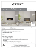
RATING LABEL LOCATION:
Figure 1. Dimensions of the Firebox.
The Rating and Lighting instruction label is located below the door frame, underneath the
fi rebox attached to a chain. To access the label, slide the plate forward out from under the
fi rebox. Always return it when fi nished.
Figure 2. Rating/Lighting Label Location.
DIMENSIONS:
An electrical junction box is provided and fastened to the right side of the fi replace. Power needs
to be brought to the electrical junction box. The power for the various control components are
all provided from the fan control module. Install the provided electric outlet and cover and plug
the the fan control module into it. See the Rating Label for the listed electrical requirements.
When installed, the L965E/HZ965E, must be electrically grounded in accordance with local
codes or, in the absence of local codes, with the National Electrical Code, ANSI/NFPA 70, or
the Canadian Electrical Code, CSA C22.1.
See Page 39.
ELECTRICAL HOOK-UP:
Regency L965E / HZ965E Gas Fireplace
5
DIMENSIONS

Figure 3. Rating Label.
ELECTRICAL RATING:(EXIGENCES ÉLECTRIQUES) Fan type circulator (Ventilateur circulaire): 120V AC 60hz/ Less than 7Amp
CLEARANCES TO COMBUSTIBLES: (DISTANCE OBLIGATOIRE DES COMBUSTIBLES)
Stove side (Côté de poêle): 4 inches (10.2cm), Back (Arriére): 4 inches (10.2cm), Ceiling from bottom of unit (Du fond
d'unité au Plafond): 80” inches (203.2cm), From fireplace frame to side wall (Du frome de la cheminée au mur latéral): 10"
(25.5 cm), From base of the unit to shelf, header, or 12" (30.5cm) mantel (De la base de l'unité à une étagère, un en-tête,
ou un 12" manteau de cheminée): 52.25" (133cm)
VENT PIPE CLEARANCES:(ESPACES LIBRES DE VENTILATION) See manufacturer’s listing, label and installation
instructions. Verifeez l’identifaction, l’etiquette et les instructionsd’installation du fabricant. This appliance must be properly
connected to a venting system in accordance with the manufacturer's installation instructions. Cet appareil doit être
convenablement connecté à un système donner vent conformément aux instructions d'installation du fabricant.
VENTED GAS FIREPLACE HEATER - NOT FOR USE WITH SOLID FUELS.
MAY BE INSTALLED IN
BEDROOM OR BEDSITTING ROOM (IN CANADA with a listed wall thermostat). THIS APPLIANCE MUST BE PROPERLY
CONNECTED TO A VENTING SYSTEM IN ACCORDANCE WITH THE MANUFACTURER'S INSTALLATION
INSTRUCTIONS. FOR DIRECT DISCHARGE WITHOUT DUCT CONNECTION. This appliance must be installed as per
manufacturers installation instructions and in accordance with local codes if any. If none exist, use current installation code
CAN/CSA B149.1 in Canada or ANSI Z223.1/NFPA 54 in the USA. This vented gas fireplace is not for use with air filters.
FOR USE WITH GLASS DOORS CERTIFIED WITH THE APPLIANCE ONLY. This appliance is only for use with the type(s)
of gas indicated on the rating plate. A conversion kit is available for this appliance. This appliance is not convertible for use
with other gases, unless a certified kit is used.
Sections of the venting system have not been installed.
WARNING: Do not operate the appliance until all sections have been assembled and installed in
accordance with the manufacturers instructions.
FOYER AU GAZ A EVACUATION - NE PAS EMPLOYER AVEC DES COMBUSTIBLES SOLIDES.
Cet
appareil peut être installé dans une chambre à coucher ou un studio. Cet appareil doit être branché correctement à un
système de conduits. Uniquement pour l'échappement direct sans raccord de conduit.Cet appareil doit être installé selon les
directives d'installation du manufacturier et selon les codes locaux, s'il y a lieu. Autrement, employez le code d'installation
en vigueur au Canada CAN/CSA B149.1. Ne pas utilliser de filtre a air avec ce foyer au gaz a evacuation. POUR L'USAGE
AVEC PORTES VITREES A CERTIFIE AVEC L'APPAREIL SEULEMENT. Cet apperareil doit etre utilise uniquement avec
le type de gaz indique sur la plaque. Cet appareil ne peut etre converti a d’autres gaz sauf si une trouse de conversion
certifee est utilisee.
ADVERTISSEMENT: Ne pas utiliser l’appareil tant que toutes les sections n’ont pas ete
assemblees et installees selon les instructions du fabricant.
MOBILE HOME: May be installed in an aftermarket, permanently located, manufactured home (USA only) or mobile home,
where not prohibited by local codes. See owner's manual for details. This appliance must be installed in accordance with the
current Standard for Mobile Homes, CAN/CSA Z240, or the Manufactured Home Construction and Safety Standard, Title 24
CFR, Part 3280, or when such standard is not applicable, the current Standard for Fire Safety Criteria for Manufactured
Home Installations, sites, and Communitties, ANSI/NFPA 501A.
LA MAISON MOBILE :
Peut être installé dans une maison mobile. Cet appareil doit être installé conformement aux Normes actuelles
pour Maisons Mobiles, le BOITE/CSA Z240, ou les Normes de Construction et de Sureté des Maisons Pré-fabriquées (Titre 24 CFR, la
Partie 3280). Quand ces Normes ne sont pas en vigueur, il faut suivre les criteres pour la sureté (contre les increndies) et pour la
construction des Maisons Pré-fabriquées, leurs sites, ANSI/NFPA 501A, et des communautées aux Instructions du manufacturier.
MANUFACTURED BY (FABRIQUE PAR) : SHERWOOD INDUSTRIES LTD. 6782 OLDFIELD RD. SAANICHTON, BC, CANADA
WH-
VENTED GAS FIREPLACE HEATER ENVIRO MODEL:
FOYER AU GAZ A EVACUATION MODELE ENVIRO:
TESTED TO / TESTÉE SELON LES NORMES:
ANSI Z21.88-2009/CSA 2.33-2009 VENTED GAS FIREPLACE HEATERS / FOYER AU GAZ EVACUATION;
CAN/CGA 2.17-M91 GAS FIRED APPLIANCES FOR HIGH ALTITUDES / LES APPAREILS BRULANT GAZ POUR
UTILISATION EN HAUTES ALTITUDES; Can/CSA P.4.1-02 (R2006) TESTING METHOD FOR MEASURING ANNUAL
FIREPLACE EFFICIENCY / LA METHODE D'ESSAI POUR MESURER L'EFFICACITE DE CHEMINEE ANNUELLE.
INPUT (ENTRÉE): NAT: 0-4500 FT (1372 M) LPG: 0-4500 FT (1372 M)
MAX: 48,000 BTU (14.07 .Wh) MAX: 48,000 BTU (14.07 .Wh)
MIN: 16,000 BTU (4.68 .Wh) MIN: 17,000 BTU (4.98 .Wh)
MANIFOLD PRESSURE (PRESSION D’ADMISSION):
NAT: 3.5 in. WC (0.87kPa) / 1.6 in. WC (0.40kPa) LPG: 10 in. WC (2.48kPa) / 6.4 in. WC (1.59kPa)
MINIMUM GAS SUPPLY PRESSURE: (PRESSION MINIMALE D'ALIMENTATION DE GAZ PERMISE)
NAT: 5 in. Wc (1.24kPa) LPG: 12 in. Wc (2.98kPa)
ORIFICE SIZE: (DIMENSIONS DE L’ORIFICE)
NAT: Left # 45 DMS, Right # 41 DMS LPG: Left # 55 DMS, Right # 53 DMS
PILOT ORIFICE SIZE: (DIMENSIONS DE PILOTER L’ORIFICE)
NAT: # 62 DMS LPG: Left # 35 DMS
NAT: (Natural Gas) LPG (Propane)
CAUTION
: Hot while in operation. Do not touch. Keep children, clothing, furniture, or gasoline and other liquids having
flammable vapors away.
ATTENTION
: Très chaud quand allumé. Ne touchez pas, les brûlures sévères peuvent résulter.
Tenez loin des enfants, des vêtements, des meubles,de l’essence ou d’autres fluides produisant des vapeurs inflammables.
DATE OF MANUFACTURE: DATE DE FABRICATION:
J F M A M J J A S O N D 2012 2013 2014 2015
DO NOT REMOVE THIS LABEL / N'ENLEVEZ PAS CETTE ETIQUETTE
Certified for use in Canada & USA
Certifié pour installation au
Canada et aux Etats-Unis.
16354
75
%
919-087
L965E
HZ965E
Manufactured in Canada for /
Fabriqué dans le Canada pour:
FPI Fireplace Products
International Ltd.
Delta, BC, Canada
COPY OF THE SAFETY LABEL
6
Regency L965E / HZ965E Gas Fireplace
SAFETY LABEL

PLANNING YOUR INSTALLATION
INTRODUCTION:
This section of the technical manual is for the use of qualifi ed technicians only. Fireplace placement, hearths, facings, mantles, and venting terminations will
be covered, as well as the gas and electric systems. There are several installation safety guidelines that must be adhered to. Please carefully read the safety
precautions at the front of this manual.
Warning: Clearances must be suffi cient to allow access for maintenance and service.
If installing a Power Vent Kit (706-922) or a Heat Distribution Kit (706-921), refer to the instructions included with the kits to aid in your planning.
NON-COMBUSTIBLE MATERIAL ZONE:
This installation guide will show you many options for installing your new L965E/HZ965E Some options include external chases, internal chases, rock facing
and corner installations. No matter what direction your installation takes, this illustration shows an area where no combustible building products may go. This
illustration applies to any and all installations for the L965E /HZ965E and should be used as the fi rst reference before any others. Failure to comply with this
requirement can lead to elevated operating temperatures, degradation of materials or even result in fi re. If you are unclear about any details contained here,
consult with your retailer prior to installation.
24"
(610mm)
**52-5/16"
(1329mm)
27-3/4"
(705mm)
11 "
(279mm)
Figure 4. Non-Combustible Material Zone.
When Installing a TV above the unit.
Regency L965E / HZ965E Gas Fireplace
7
INSTALLATION

Figure 6. Typical Framing for Internal Chase - Detailed.
63"
(1600mm)
to centerline
24"
(610mm)
Min. Chase Depth
52-5/16"
(1329mm)
Minimum
52-5/16"
(1329mm)
To Header
44-3/4"
(1137mm)
Minimum
Figure 5. Typical Framing for Internal Chase - General.
FRAMING:
INTERNAL CHASE:
NOTE:
Framing chase depth is 26-1/2”
when using the heat distribution kit.
Internal ceiling clearance is 90”
when using the heat distribution kit.
8
Regency L965E / HZ965E Gas Fireplace
INSTALLATION

Hearth Protector
Figure 7. Typical Framing for External Chase - General.
Figure 8. Typical Framing for External Chase - Detailed.
63"
(1600mm)
to centerline
24"
(610mm)
Min. Chase Depth
52-5/16"
(1329mm)
To Header
44-3/4"
(1137mm)
Minimum
EXTERNAL CHASE:
Non-Combustible Facing and Hearth Protector
Dimensions:
Facing (supplied)
1 Top = 46” x 19”
2 Sides = 32-15/16 x 4-9/16”
Hearth Protector (supplied)
46” x 12”
NOTE: No hearth is required if the unit is raised a
minimum of 18” off the fl oor.
Regency L965E / HZ965E Gas Fireplace
9
INSTALLATION

Figure 10. Typical Framing for Corner - Detailed.
44-3/4"
(1137mm)
Minimum
5
2-5/16"(1329mm)
Minimum to
Header/Shelf
Height from Base
of Unit
64”
(1626mm)
Figure 9. Typical Framing for Corner - General.
CORNER FRAMING:
10
Regency L965E / HZ965E Gas Fireplace
INSTALLATION

2
0
12
6
4
810
0
14
Non-combustible
Facing
To Unit
Base
18-1/2”
33-1/4”
10
20
26
Top of
Fireplace
Opening
10" (254mm)
No Mantel
Here
Mantel Trim
(max. of 1-1/4")
4"
(102mm)
Figure 11. Mantel Clearances
Figure 12. Typical Framing for Sidewalls & Mantel - Detailed.
Minimum
Fireplace Base to
Combustible Mantel
44-3/4"(1 137mm )
Minimum
Framing Width
51-3/4" (1314mm)
The mantel’s maximum overhang is 10” (254mm)
at the minimum height of 52¼” (1327mm)
measured from the base of the fi replace.
The mantel can extend 1” (25.4mm) further for
every 1” (25.4mm) of height it is installed over the
minimum height, as shown in Figure 12.
Non-combustible mantels and mantel legs are
not limited to these dimensions.
Mantel temperatures are monitored during
testing and can reach 117°F (47°C) above room
temperatures. Make sure the fi nish on your
mantel is suitable for temperatures of this range.
A wood trim can overhang a maximum of
1-1/4”deep and 14-1/2” in height from the top of
the unit as shown in fi gures 11 and 12.
FRAMING FOR SIDEWALLS AND MANTEL:
Regency L965E / HZ965E Gas Fireplace
11
INSTALLATION

Figure 14. Typical Framing for a Raised Hearth - Detailed.
TYPICAL FRAMING - RAISED HEARTH:
Warning: Failure to follow these guidelines may result in elevated operating temperatures, an inability to remove or install the door.
A non-combustible Hearth Insulation Board is required to be installed between any non-combustible hearth covering and any combustible fl oor-
ing beneath.
The design of the unit is such that the fi replace must
be raised by the same distance as any additional
hearth covering or riser that are added in front of
the fi replace.
Figure 14 shows a raised hearth made of a wooden
construction hearth riser (B), covered with the insu-
lation board provided and then covered with non-
52-5/16"(1329mm)
Minimum to
Combustible
Header Height
from Base of Unit
Figure 13. Typical Framing for a Raised Hearth - General.
combustible slate (A). The thickness of the riser (B)
is 4” (102mm). The thickness of the slate (A) is 2”
(52mm). A+B=C which is 6” (152mm). In summary,
the fi replace must be raised by the same thickness
of any material added in front of the fi replace.
If the raised hearth is deeper or wider than the
Insulation Board provided with the unit, additional
non-combustible materials such as Backer Board
(cement board) can be used to build up to the same
thickness as the Insulation Board.
All header, ceiling or shelf dimensions are measured
from the fl oor that the fi replace sits on. Failure to
maintain minimum installation dimensions can lead
to elevated temperatures, fi re or personal injury.
For optional Reduced Ceiling Height installations,
see Appendix A.
Non-combustible
Hearth Pad
Figure 15. Fireplace Section for a Raised
Hearth - WARNING.
The insulation board supplied with
this unit is 46”width x 12” depth x 1/2”
thick.
Any additional material such as
marble must be the same width and
depth as the insulation board.
12
Regency L965E / HZ965E Gas Fireplace
INSTALLATION

Figure 16. Typical Facing for the Fireplace - General.
There are three (3) options for installing facing to your fi replace installation. Care must be
taken to ensure proper clearances are maintained.
Failure to maintain this clearance will lead to elevated operating temperatures and possible
discoloration of materials.
Three (3) possible installations include:
1) For fi replace facing less than 1” thick (total facing and non-combustible board combined)
with an optional front installed.
2) For fi replace facing greater than 1” thick with an optional front installed.
3) For any fi replace facing without an optional front installed.
Figures 17 to 19 highlight the relationships between the fi replace, optional front, and facing
installed.
Figure 17. Option 1 - Fireplace Facing Less
Than 1” (25.4mm) Thick.
NOTE: REQUIRES 5/8”(16mm)_AIR GAP
INSTALLATION OF FIREPLACE FACING:
Figure 18. Option 2 - Fireplace Facing More
Than 1” (25.4mm) Thick With Optional Front
Installed.
NOTE: REQUIRES 3/4”(19mm) AIR GAP
Figure 19. Option 3 - Any Fireplace Facing
Without Optional Front Installed.
Regency L965E / HZ965E Gas Fireplace
13
INSTALLATION

Figure 22. Receiver Installation.
The Receiver is the heart of the remote control system. You need to access this receiver after installation to change the batteries (for operation
during a power failure), to program a new remote / receiver combination and to operate a manual override should you lose your remote control
or the batteries in the remote control lose their power.
The Receiver is connected to the fi replace with a wire harness that has a maximum length of 8 ft (2.4m). The connection point on the fi replace
is on the right side of the unit, where the gas valve and electronic ignition module is located. Because of the 8 ft (2.4m) limitation in the wiring
harness, the receiver needs to be mounted to the right side of the fi replace. An electrical box is provided for the receiver. Mount this electrical
box as you would any electrical outlet or switch box. Thread the cable and connector through the back of the electrical box and connect it to
the rear of the receiver. Secure the receiver into the electrical box. Once the facing of the fi replace installation is complete, install the receiver
cover, supplied with the unit as shown. The receiver cover also functions as a switch plate and allows for access to the program button, critical
for remote control operation.
Review the section in this manual regarding the remote control operations for more information on the functions of the receiver.
RECEIVER INSTALLATION
14
Regency L965E / HZ965E Gas Fireplace
INSTALLATION

Table 1: Vent Restrictor Sizes.
%
Restriction
Ø of Flue
Restrictor
40%
3.878”
(98.5mm)
50%
3.540”
(89.9mm)
60%
3.166”
(80.4mm)
70%
2.742”
(69.6mm)
80%
2.239”
(56.9mm)
Figure 23. Allowable Vent Confi gurations Chart.
ALLOWABLE VENT CONFIGURATIONS:
The vent chart, in Figure 23, illustrates the vent confi gurations that have been tested and approved for use with this appliance. 45˚ elbows are acceptable for
this installation and may be used instead of 90˚ elbows. You may use two (2) 45˚ elbows for every 90˚ elbow shown in this chart.
This appliance is also approved for use with 5” x 8” fl ex venting. Only use fl exible venting that is approved for this appliance. Flex vent runs must comply with
the same limitations as the rigid vent chart shown here. Flexible vent runs greater than 10’ total are not permitted. When using the fl exible vent system, part #
946-601 5” x 8” fl ex pipe adaptor must be used to adapt from rigid venting to fl ex venting. This must be attached to the appliance prior to attaching fl ex venting.
The restrictor settings shown in Figure 23, are recommended. Installation factors such as altitude, prevailing weather conditions such as temperature or
wind, or the number of elbows used may affect your fi nal restrictor settings. Insuffi cient restriction may cause pilot outages or reduced effi ciencies. Too much
restriction may lead to elevated operating temperatures, poor fl ame appearances, sooting or carbon deposits building up on burner effects or window glass.
Only use the restrictors supplied with this appliance.
Regency L965E / HZ965E Gas Fireplace
15
INSTALLATION

16
Figure 24. Vent Termination Restrictions, refer to Table 2.
A
A
D
E
L
B
C
F
B
B
B
J
M
K
G
H
I
Openable
Fixed
Closed
Openable
Fixed
Closed
Termination Cap
Air Supply Inlet
Gas Meter
G
G
Restriction Zone
(Termination not allowed)
N
O
1
In accordance with the current CSA B149, Natural Gas and Propane Installation Code.
2
In accordance with the current ANSI Z223.1 NFPA 54, National Fuel Gas Code.
* These numbers are only estimates. Clearance in accordance with installation codes and the requirements of the gas supplier.
t
A vent shall not terminate directly above a side walk or paved driveway that is located between two single family dwellings and it serves both dwellings.
+
Permitted only if verandah, porch, deck, or balcony is fully open on a minimum of two sides beneath the fl oor.
NOTE: Venting terminals shall not be recessed into walls or siding.
VENT TERMINATION RESTRICTIONS:
NOT FOR POWER VENT SYSTEM - IF USING POWER VENT - SEE PAGE 37.
Letter Canadian Installation
1
US Installation
2
Description
A 12 in (30 cm) Clearance above grade, verandah, porch, deck, or
balcony.
B 12 in (30 cm) 9 in (23 cm) Clearance from window or door that may be opened.
C 12 in (30 cm)* Clearance from permanently closed window (to prevent
condensation).
D 19¼ in (49 cm) Vertical clearance to ventilated soffi t located above the
terminal, within a horizontal distance of 2 ft (60 cm)
from center line of terminal.
E 19¼ in (49 cm) Clearance to unventilated soffi t.
F 17¼ in (44 cm)* Clearance to outside corner.
G 17¼ in (44 cm) Clearance to inside corner.
H 3 ft (91 cm) within a height
of 15 ft (4.5 m) above the
meter/regulator assembly
3 ft (91 cm) within a height of
15 ft (4.5 m) above the meter/
regulator assembly*
Clearance to each side of center line extended above
meter/regulator assembly.
I 3 ft (91 cm) 3 ft (91 cm)* Radial clearance around service regulator vent outlet.
J 12 in (30 cm) 9 in (23 cm) Clearance to non-mechanical air supply inlet to building,
or the combustion air inlet to any other appliance.
K 6 ft (1.83 m) 3 ft (91 cm) above if within 10
ft (3 m) horizontally
Clearance to mechanical air supply inlet.
L 7 ft (2.13 m
)t
7 ft (2.13 m)
*t
Clearance above paved sidewalk or paved driveway
located on public property.
M 19¼ in (49 cm)
+
Clearance under verandah, porch, deck, or balcony.
N 12 in (30 cm)* Clearance horizontally to any surface (such as an exte-
rior wall) for vertical terminations.
O 12 in (30 cm) Clearance above roof line for vertical terminations.
Table 2: Vent termination clearances, refer to Figure 24.
16
Regency L965E / HZ965E Gas Fireplace
INSTALLATION

APPROVED VENT PARTS:
Table 3: Vent part numbers (Must state if galvanized or black wanted, PART NUMBERS).
Part Description
Simpson
Duravent
Security Chim.
American
Metal
Selkirk Int. Metal-Fab EXCELDirect
6” Pipe Length
58DVA-06 SV5L6 5D7 5DT-06 5D6 TC-5DL6
9” Pipe Length
58DVA-09 5DT-09
12” Pipe Length
58DVA-12 SV5L12 5D12 5DT-12 5D12 TC-5DL1
24” Pipe Length
58DVA-24 SV5L24 5D2 5DT-24 5D24 TC-5DL2
36” Pipe Length
58DVA-36 SV5L36 5D3 5DT-36 5D36
48” Pipe Length
58DVA-48 SV5L48 5D4 5DT-48 5D48 TC-5DL4
60” Pipe Length
58DVA-60
8 ½” Pipe Extension
58DVA-08A SV5LA12(12”)
5D7A
5D12A
5DT-AJ12 5DAL
16” Pipe Extension
58DVA-16A SV5LA24(24”)
5D16A
5D26A
Flexible Length, 36” TC-5DLF
12” Adjustable Length TC-5DLT
45° Elbow
58DVA-E45 SV5E45 5D45L 5DT-EL45 5D45L TE-5DE45
90° Elbow
58DVA-E90 SV5E90 5D90L 5DT-EL90 5D90L TE-5DE90
Roof Flashing
58DVA-F6
SV5F /
SV5FA / SV5FB
5DF12
5DT-AF6
5DT-AF12
5DF
XF-6EF / XF-6EFA
/XF-6EFB
Storm Collar
58DVA-SC SV5FC 5DSC 5DT-SC 5DSC TM-SC
Ceiling Firestop
58DVA-FS SV5BF 5DFSP 5DT-FS TM-5CS
Wall Firestop
58DVA-WFS 5DFS
Wall Thimble
58DVA-WT SV5RMS 5DWT 5DT-WT 5DWT TM-5WT
Horiz. Square
Termination
58DVA-HC-* SV5CHC 5DHCS 5DT-HC 5DHT TM-5HT/TM-5DHT
Horiz. Round Termination
5DHC
Horizontal Sconce
Termination
Vert. Termination, High
Wind
58DVA-VCH SV5CGV 5DVC 5DT-VT 5DVT
Vinyl Siding Standoff
58DVA-VSS SV5VS 5DHVS 5DT-VS 5DVS TM-VSS
Flex Venting 5” and 8”
Durafl ex
*Several color choices
IMPORTANT: This chart covers the major components for each of these manufacturers only. Refer to the manufacturers’ catalogue for further
details on roof fl ashings and other installation items
The L965E/HZ965E fi replace has been tested and certifi ed for use with AMERICAN METAL PRODUCTS “AMERIVENT DIRECT”, SIMPSON
DURAVENT TYPE GS PIPE FOR GAS STOVES. SECURITY CHIMNEY’S “SECURE VENT DIRECT VENT SYSTEM”, SELKIRK “DIRECT-
TEMP VENT SYSTEM”, and EXCELDIRECT “ICC“ kits are available for horizontal and vertical venting. When planning an installation, it will be
necessary to select the proper length of vent pipe for the particular requirements.
WARNING: Do not mix parts from different vent manufacturers’ systems.
EXCEPTION TO WARNING: This product has been evaluated by Intertek for using a Direct Vent GS starting collar in conjunction with Secure
Vent, Direct-Temp, and Ameri Vent Direct venting systems. Use of these systems with the Direct Vent GS starting collar is deemed acceptable
and does not affect the Intertek WH listing of the appliance.
Regency L965E / HZ965E Gas Fireplace
17
INSTALLATION

Table 4: Approved Vent Manufacturers
Manufacturer Trade Name Nominal Sizes
American Metal Products AmeriVent Direct
5” x 8”
Security Chimneys International LTD Secure Vent
5” x 8”
Selkirk Metalbestos Direct-Temp
5” x 8”
Simpson Dura-Vent Direct Vent GS
5” x 8”
EXCELDirect ICC
5” x 8”
INSTALLATION OF FLUE RESTRICTOR:
Flue Restrictors are necessary to keep the
fi replace running at its intended effi ciency. They
are also required to counteract the effect that
taller vertical vent runs may have on the appliance.
The additional venting action that tall vertical vent
systems may have can result in poor pilot and/
or burner operations and possibly nuisance shut
downs. Generally, the vent restriction may be less
than what is shown in the vent chart, but not greater.
The vent restrictor size is shown in percentages,
meaning that a 40% restrictor restricts the vent
40% from its fully un-restricted vent size.
1) Remove the Glass Door; refer to DOOR
REMOVAL AND INSTALLATION.
2) Remove the Burner and/or Log Set; refer
to BURNER REMOVAL AND INSTALLATION.
3) Remove the Refl ective or Brick Panels;
refer to REFLECTIVE OR BRICK PANEL
INSTALLATION.
4) Refer to the Vent Chart (Figure 23) for selection
of the appropriate Restrictor.
5) Using the two (2) ¼” T-20 screws provided with
the restrictor, fasten the Restrictor into the Flue
Outlet as shown in Figures 25 & 26. Make sure
the diagonal holes line up with the diagonal holes
located in the Flue Outlet Box Use a powered
driver to drive the screw in. Be careful not to
over-torque the screw and strip the threads.
6) Re-install the Light Covers, Firebox Liners, Burners and log sets and the Glass Door.
7) Run the unit for ½ hour to check for proper operations and fl ame appearance.
Figure 25: Installation of Flue Restrictor.
Figure 26: Installation of Flue Restrictor -
Close-Up.
18
Regency L965E / HZ965E Gas Fireplace
INSTALLATION

Figure 27: Installation of TV Above the Unit.
TV INSTALLATION ABOVE UNIT:
During the development of the L965E/HZ965E, we took into consideration that in some installations TV’s or fl at panel monitors may be located above the
mantel. Although we can not anticipate every possible installation variable, we took time to evaluate the suitability of the installation of a TV or Plasma display
above the mantel. We carried out testing to evaluate what possible operating temperatures that may be experienced when the appliance was installed in an
internal chase. A mantel was installed with the maximum overhang at the minimum allowable installation height, with a full 13” (330mm) shelf installed over
the unit (see section NON-COMBUSTIBLE MATERIAL ZONE).
The area above the mantel, within 4 inches (102mm) of the wall was measured under maximum operating conditions and found to not exceed 120°F (49°C).
Variations of mantel overhangs, shelf depths or ceiling heights will affect this temperature. Please refer the TV owner’s manual for information on acceptable
operating conditions. Care must be taken to evaluate your specifi c installation and operating conditions when deciding to install electronic equipment above
or near this appliance when it is in operation. Always consult your TVs owner’s manual to ensure that this application is an approved installation.
IMPORTANT: Temperature acceptance levels in TV’s vary greatly. Before installing any electronic appliance above this fi replace, fi rst
verify temperature requirements from the TV manufacturer. See temperatures above for guidance. Regency will not be
responsible for heat damage to electronic appliances.
SEE NOTE BELOW
Regency L965E / HZ965E Gas Fireplace
19
INSTALLATION

QUALIFIED INSTALLERS ONLY
PLANNING YOUR INSTALLATION:
Prior to starting your venting installation, refer to the section on Allowable Vent Confi gurations to make sure your plans fall into the allowable limits of
horizontal and vertical installations.
When planning your installation, it will be necessary to select the proper length of vent pipe for your particular requirements. For horizontal installations,
refer to the section on Clearances to Combustibles to determine the minimum clearance from the rear of the appliance to the wall. It is also important
to note the wall thickness. Select the amount of vertical rise desired for “vertical-to- horizontal” type installations. To determine the length of vent pipe
required for vertical installations, measure the distance from the appliance fl ue outlet to the ceiling, the ceiling thickness, the vertical rise in an attic or
second story, and allow for suffi cient vent height above the roofl ine. For two-story applications, fi restops are required at each fl oor level. If an offset is
needed in the attic, additional pipe and elbows will be required.
ASSEMBLY OF THE UNIT:
1. Using eight (8) T-20 screws provided, install the
facing supports right and left as well as the heat
shield in the middle, as shown in Figure 28.
2. Using eight (8) T20 screws provided, attach
both back stand-offs, as shown in Figure 29.
SECURING UNIT INTO POSITION:
Once the unit is in its fi nal position, confi rm that you have access to power, gas
supply, that your non-combustible zone requirements are met, that you meet all the
minimum vent requirements, and that your planned vent terminal location will meet
all of the vent termination clearances. Secure the unit to the fl oor, with at least four
(4) wood screws, two (2) on either side of the unit’s bottom nailing fl ange. Secure the
side stand-offs to the framing members using four (4) wood screws, one (1) for each
stand-off and to the header, one (1) wood screw for each facing support.
Left and Right
Facing Support
Figure 28: Installation of Supports & Heat
shield.
Figure 30: Securing the Unit.
Figure 29: Installation of Back Stand-Offs.
20
Regency L965E / HZ965E Gas Fireplace
INSTALLATION
/