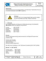
Duerkopp Adler 506-3 User manual
- Category
- Sewing machines
- Type
- User manual
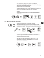
The Duerkopp Adler 506-3 sewing machine is an industrial-grade machine designed for reliable and efficient sewing operations. It features a hook monitor system that prevents sewing without a bobbin thread, ensuring uninterrupted operation. The machine also includes a thread break sensor that automatically stops sewing when the thread breaks, minimizing fabric waste and production downtime. Additionally, the 506-3 has a self-test function that allows for quick and easy troubleshooting, reducing maintenance time and costs.
The Duerkopp Adler 506-3 sewing machine is an industrial-grade machine designed for reliable and efficient sewing operations. It features a hook monitor system that prevents sewing without a bobbin thread, ensuring uninterrupted operation. The machine also includes a thread break sensor that automatically stops sewing when the thread breaks, minimizing fabric waste and production downtime. Additionally, the 506-3 has a self-test function that allows for quick and easy troubleshooting, reducing maintenance time and costs.


-
 1
1
-
 2
2
-
 3
3
-
 4
4
-
 5
5
-
 6
6
-
 7
7
-
 8
8
-
 9
9
-
 10
10
-
 11
11
-
 12
12
-
 13
13
-
 14
14
-
 15
15
-
 16
16
-
 17
17
-
 18
18
-
 19
19
-
 20
20
-
 21
21
-
 22
22
-
 23
23
-
 24
24
-
 25
25
-
 26
26
-
 27
27
-
 28
28
-
 29
29
-
 30
30
-
 31
31
-
 32
32
-
 33
33
-
 34
34


Duerkopp Adler 506-3 User manual
- Category
- Sewing machines
- Type
- User manual
The Duerkopp Adler 506-3 sewing machine is an industrial-grade machine designed for reliable and efficient sewing operations. It features a hook monitor system that prevents sewing without a bobbin thread, ensuring uninterrupted operation. The machine also includes a thread break sensor that automatically stops sewing when the thread breaks, minimizing fabric waste and production downtime. Additionally, the 506-3 has a self-test function that allows for quick and easy troubleshooting, reducing maintenance time and costs.
Ask a question and I''ll find the answer in the document
Finding information in a document is now easier with AI
in other languages
Related papers
-
 Duerkopp Adler 366 Operating instructions
-
 Duerkopp Adler 467-65 User manual
-
 Duerkopp Adler 749-5 Operating instructions
-
 Duerkopp Adler 204-370 User manual
-
 Duerkopp Adler 275 User manual
-
 Duerkopp Adler 275 User manual
-
Duerkopp Adler 975 User manual
-
 Duerkopp Adler 367 - INSTRUCTIONS FOR FITTING FOR KIT 0367 595144 User manual
-
 Duerkopp Adler 267 Operating instructions
-
 Duerkopp Adler 867 User manual


Other documents
-
DURKOPP ADLER 506-3 Manual Motor
-
-
-
 Audio Authority 9850 User guide
-
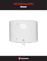 SE Electronics Reflexion Filter Pro Owner's manual
-
T+A R 1230 R User manual
-
Philips 9850 User manual
-
 DURKOPP 911-210 Owner's manual
-
-
SunStar KM-250 Series User manual


