
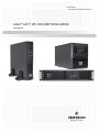
AC Power
For Business-Critical Continuity™
Liebert
®
GXT3
™
UPS 120V/208V 500VA-3000VA
User Manual


i
TABLE OF CONTENTS
IMPORTANT SAFETY PRECAUTIONS . . . . . . . . . . . . . . . . . . . . . . . . . . . . . . . . . . . . . . . . . . . . . . . .1
SAVE THESE INSTRUCTIONS . . . . . . . . . . . . . . . . . . . . . . . . . . . . . . . . . . . . . . . . . . . . . . . . . . . . .1
GLOSSARY OF SYMBOLS . . . . . . . . . . . . . . . . . . . . . . . . . . . . . . . . . . . . . . . . . . . . . . . . . . . . . . . .3
1.0 PRODUCT DESCRIPTION . . . . . . . . . . . . . . . . . . . . . . . . . . . . . . . . . . . . . . . . . . . . . . . . . . .4
1.1 Features . . . . . . . . . . . . . . . . . . . . . . . . . . . . . . . . . . . . . . . . . . . . . . . . . . . . . . . . . . . . . . . . . . . 4
1.2 Available Models . . . . . . . . . . . . . . . . . . . . . . . . . . . . . . . . . . . . . . . . . . . . . . . . . . . . . . . . . . . . 4
1.3 Appearance and Components . . . . . . . . . . . . . . . . . . . . . . . . . . . . . . . . . . . . . . . . . . . . . . . . . . 5
1.3.1 Front Panel and Controls. . . . . . . . . . . . . . . . . . . . . . . . . . . . . . . . . . . . . . . . . . . . . . . . . . . . . . . 5
1.3.2 Rear Panel Features. . . . . . . . . . . . . . . . . . . . . . . . . . . . . . . . . . . . . . . . . . . . . . . . . . . . . . . . . . . 5
1.4 Major Components . . . . . . . . . . . . . . . . . . . . . . . . . . . . . . . . . . . . . . . . . . . . . . . . . . . . . . . . . . . 8
1.5 Operating Mode . . . . . . . . . . . . . . . . . . . . . . . . . . . . . . . . . . . . . . . . . . . . . . . . . . . . . . . . . . . . . 9
1.5.1 Utility (AC) Mode . . . . . . . . . . . . . . . . . . . . . . . . . . . . . . . . . . . . . . . . . . . . . . . . . . . . . . . . . . . . . 9
1.5.2 Manual Bypass Mode . . . . . . . . . . . . . . . . . . . . . . . . . . . . . . . . . . . . . . . . . . . . . . . . . . . . . . . . . . 9
1.5.3 Battery Mode . . . . . . . . . . . . . . . . . . . . . . . . . . . . . . . . . . . . . . . . . . . . . . . . . . . . . . . . . . . . . . . 10
1.5.4 Battery Recharge Mode . . . . . . . . . . . . . . . . . . . . . . . . . . . . . . . . . . . . . . . . . . . . . . . . . . . . . . . 10
1.5.5 Frequency Converter Mode . . . . . . . . . . . . . . . . . . . . . . . . . . . . . . . . . . . . . . . . . . . . . . . . . . . . 10
2.0 INSTALLATION . . . . . . . . . . . . . . . . . . . . . . . . . . . . . . . . . . . . . . . . . . . . . . . . . . . . . . . . . 11
2.1 Unpacking and Inspection . . . . . . . . . . . . . . . . . . . . . . . . . . . . . . . . . . . . . . . . . . . . . . . . . . . . 11
2.2 What’s Included . . . . . . . . . . . . . . . . . . . . . . . . . . . . . . . . . . . . . . . . . . . . . . . . . . . . . . . . . . . . 11
2.3 Preparation for Installation . . . . . . . . . . . . . . . . . . . . . . . . . . . . . . . . . . . . . . . . . . . . . . . . . . . 11
2.3.1 Installation Environment. . . . . . . . . . . . . . . . . . . . . . . . . . . . . . . . . . . . . . . . . . . . . . . . . . . . . . 11
2.4 Mechanical Installation . . . . . . . . . . . . . . . . . . . . . . . . . . . . . . . . . . . . . . . . . . . . . . . . . . . . . . 12
2.4.1 Tower Installation . . . . . . . . . . . . . . . . . . . . . . . . . . . . . . . . . . . . . . . . . . . . . . . . . . . . . . . . . . . 12
2.4.2 Rack Installation . . . . . . . . . . . . . . . . . . . . . . . . . . . . . . . . . . . . . . . . . . . . . . . . . . . . . . . . . . . . 14
2.5 Cable Connection . . . . . . . . . . . . . . . . . . . . . . . . . . . . . . . . . . . . . . . . . . . . . . . . . . . . . . . . . . . 17
2.5.1 Connecting Input Plug and Loads . . . . . . . . . . . . . . . . . . . . . . . . . . . . . . . . . . . . . . . . . . . . . . . 17
2.5.2 Connecting Battery Cables . . . . . . . . . . . . . . . . . . . . . . . . . . . . . . . . . . . . . . . . . . . . . . . . . . . . 17
2.6 Connecting Communication Cables. . . . . . . . . . . . . . . . . . . . . . . . . . . . . . . . . . . . . . . . . . . . . 18
2.6.1 Connecting USB Communication Cables . . . . . . . . . . . . . . . . . . . . . . . . . . . . . . . . . . . . . . . . . 18
2.6.2 Installing the Optional Liebert IntelliSlot
®
Card and Communication Cables . . . . . . . . . . . 18
3.0 CONTROLS AND INDICATORS. . . . . . . . . . . . . . . . . . . . . . . . . . . . . . . . . . . . . . . . . . . . . . .19
3.1 Control Buttons . . . . . . . . . . . . . . . . . . . . . . . . . . . . . . . . . . . . . . . . . . . . . . . . . . . . . . . . . . . . 19
3.1.1 On/Alarm Silence/Manual Battery Test Button . . . . . . . . . . . . . . . . . . . . . . . . . . . . . . . . . . . . 19
3.1.2 Standby/Manual Bypass Button . . . . . . . . . . . . . . . . . . . . . . . . . . . . . . . . . . . . . . . . . . . . . . . . 19
3.2 Indicators . . . . . . . . . . . . . . . . . . . . . . . . . . . . . . . . . . . . . . . . . . . . . . . . . . . . . . . . . . . . . . . . . 20
3.2.1 Level Indicators . . . . . . . . . . . . . . . . . . . . . . . . . . . . . . . . . . . . . . . . . . . . . . . . . . . . . . . . . . . . . 20
3.2.2 UPS Status Indicators . . . . . . . . . . . . . . . . . . . . . . . . . . . . . . . . . . . . . . . . . . . . . . . . . . . . . . . . 21

ii
4.0 OPERATION . . . . . . . . . . . . . . . . . . . . . . . . . . . . . . . . . . . . . . . . . . . . . . . . . . . . . . . . . . .22
4.1 Startup Checklist for the Liebert GXT3 . . . . . . . . . . . . . . . . . . . . . . . . . . . . . . . . . . . . . . . . . 22
4.2 Starting the UPS . . . . . . . . . . . . . . . . . . . . . . . . . . . . . . . . . . . . . . . . . . . . . . . . . . . . . . . . . . . 22
4.3 Manual Battery Test . . . . . . . . . . . . . . . . . . . . . . . . . . . . . . . . . . . . . . . . . . . . . . . . . . . . . . . . 22
4.4 Manual Bypass . . . . . . . . . . . . . . . . . . . . . . . . . . . . . . . . . . . . . . . . . . . . . . . . . . . . . . . . . . . . . 22
4.5 Shut Down the Liebert
®
GXT3
™
. . . . . . . . . . . . . . . . . . . . . . . . . . . . . . . . . . . . . . . . . . . . . . . 23
4.6 Disconnecting Input Power from the Liebert GXT3. . . . . . . . . . . . . . . . . . . . . . . . . . . . . . . . 23
5.0 COMMUNICATION . . . . . . . . . . . . . . . . . . . . . . . . . . . . . . . . . . . . . . . . . . . . . . . . . . . . . . .24
5.1 Liebert IntelliSlot Communication Cards. . . . . . . . . . . . . . . . . . . . . . . . . . . . . . . . . . . . . . . . 24
5.1.1 Liebert MultiLink. . . . . . . . . . . . . . . . . . . . . . . . . . . . . . . . . . . . . . . . . . . . . . . . . . . . . . . . . . . . 24
5.2 USB Port Communication . . . . . . . . . . . . . . . . . . . . . . . . . . . . . . . . . . . . . . . . . . . . . . . . . . . . 25
5.2.1 Configuration Program . . . . . . . . . . . . . . . . . . . . . . . . . . . . . . . . . . . . . . . . . . . . . . . . . . . . . . . 25
5.3 Terminal Block Communication . . . . . . . . . . . . . . . . . . . . . . . . . . . . . . . . . . . . . . . . . . . . . . . 26
5.3.1 Any-Mode Shutdown . . . . . . . . . . . . . . . . . . . . . . . . . . . . . . . . . . . . . . . . . . . . . . . . . . . . . . . . . 26
5.3.2 Battery Mode Shutdown . . . . . . . . . . . . . . . . . . . . . . . . . . . . . . . . . . . . . . . . . . . . . . . . . . . . . . 27
5.3.3 On Battery . . . . . . . . . . . . . . . . . . . . . . . . . . . . . . . . . . . . . . . . . . . . . . . . . . . . . . . . . . . . . . . . . 27
5.3.4 Low Battery . . . . . . . . . . . . . . . . . . . . . . . . . . . . . . . . . . . . . . . . . . . . . . . . . . . . . . . . . . . . . . . . 27
6.0 MAINTENANCE . . . . . . . . . . . . . . . . . . . . . . . . . . . . . . . . . . . . . . . . . . . . . . . . . . . . . . . . .28
6.1 Replacing the Internal Battery Pack. . . . . . . . . . . . . . . . . . . . . . . . . . . . . . . . . . . . . . . . . . . . 28
6.1.1 Battery Replacement Procedures . . . . . . . . . . . . . . . . . . . . . . . . . . . . . . . . . . . . . . . . . . . . . . . 28
6.2 Battery Charging . . . . . . . . . . . . . . . . . . . . . . . . . . . . . . . . . . . . . . . . . . . . . . . . . . . . . . . . . . . 30
6.3 Precautions . . . . . . . . . . . . . . . . . . . . . . . . . . . . . . . . . . . . . . . . . . . . . . . . . . . . . . . . . . . . . . . . 30
6.4 Checking UPS Status . . . . . . . . . . . . . . . . . . . . . . . . . . . . . . . . . . . . . . . . . . . . . . . . . . . . . . . . 30
6.5 Checking UPS Functions . . . . . . . . . . . . . . . . . . . . . . . . . . . . . . . . . . . . . . . . . . . . . . . . . . . . . 30
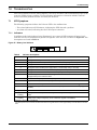
7.0 TROUBLESHOOTING . . . . . . . . . . . . . . . . . . . . . . . . . . . . . . . . . . . . . . . . . . . . . . . . . . . . .31
7.1 UPS Symptoms. . . . . . . . . . . . . . . . . . . . . . . . . . . . . . . . . . . . . . . . . . . . . . . . . . . . . . . . . . . . . 31
7.1.1 Indicators . . . . . . . . . . . . . . . . . . . . . . . . . . . . . . . . . . . . . . . . . . . . . . . . . . . . . . . . . . . . . . . . . . 31
7.1.2 Audible Alarm. . . . . . . . . . . . . . . . . . . . . . . . . . . . . . . . . . . . . . . . . . . . . . . . . . . . . . . . . . . . . . . 32
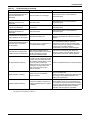
7.2 Troubleshooting . . . . . . . . . . . . . . . . . . . . . . . . . . . . . . . . . . . . . . . . . . . . . . . . . . . . . . . . . . . . 32
8.0 BATTERY CABINET . . . . . . . . . . . . . . . . . . . . . . . . . . . . . . . . . . . . . . . . . . . . . . . . . . . . . .34
9.0 S
PECIFICATIONS . . . . . . . . . . . . . . . . . . . . . . . . . . . . . . . . . . . . . . . . . . . . . . . . . . . . . . . .35
9.1 Product Warranty Registration . . . . . . . . . . . . . . . . . . . . . . . . . . . . . . . . . . . . . . . . . . . . . . . . 39

iii
FIGURES
Figure 1 Liebert GXT3 rack/tower models—front view . . . . . . . . . . . . . . . . . . . . . . . . . . . . . . . . . . . . . . . . . . 5
Figure 2 Liebert GXT3 minitower—front view . . . . . . . . . . . . . . . . . . . . . . . . . . . . . . . . . . . . . . . . . . . . . . . . 5
Figure 3 Liebert
®
GXT3
™
120V rack/tower models—rear panel components . . . . . . . . . . . . . . . . . . . . . . . . 6
Figure 4 Liebert
®
GXT3
™
208V rack/tower models—rear panel components . . . . . . . . . . . . . . . . . . . . . . . . 7
Figure 5 Liebert GXT3-1000MT120
™
—rear panel components . . . . . . . . . . . . . . . . . . . . . . . . . . . . . . . . . . . 7
Figure 6 Operating principle diagram . . . . . . . . . . . . . . . . . . . . . . . . . . . . . . . . . . . . . . . . . . . . . . . . . . . . . . . 8
Figure 7 Support bases . . . . . . . . . . . . . . . . . . . . . . . . . . . . . . . . . . . . . . . . . . . . . . . . . . . . . . . . . . . . . . . . . . 12
Figure 8 Remove the front plastic bezel cover . . . . . . . . . . . . . . . . . . . . . . . . . . . . . . . . . . . . . . . . . . . . . . . . 12
Figure 9 Rotate the operation and display panel . . . . . . . . . . . . . . . . . . . . . . . . . . . . . . . . . . . . . . . . . . . . . . 13
Figure 10 Tower installation . . . . . . . . . . . . . . . . . . . . . . . . . . . . . . . . . . . . . . . . . . . . . . . . . . . . . . . . . . . . . . . 13
Figure 11 Pulling inner member from each slide rail assembly . . . . . . . . . . . . . . . . . . . . . . . . . . . . . . . . . . . 14
Figure 12 Installing rear member of each slide rail assembly . . . . . . . . . . . . . . . . . . . . . . . . . . . . . . . . . . . . 14
Figure 13 Installing front member of each slide rail assembly . . . . . . . . . . . . . . . . . . . . . . . . . . . . . . . . . . . . 15
Figure 14 Fastening rear member and front member together . . . . . . . . . . . . . . . . . . . . . . . . . . . . . . . . . . . 15
Figure 15 Installing inner members . . . . . . . . . . . . . . . . . . . . . . . . . . . . . . . . . . . . . . . . . . . . . . . . . . . . . . . . . 15
Figure 16 Installing rack-mount handles . . . . . . . . . . . . . . . . . . . . . . . . . . . . . . . . . . . . . . . . . . . . . . . . . . . . . 16
Figure 17 Insert the UPS. . . . . . . . . . . . . . . . . . . . . . . . . . . . . . . . . . . . . . . . . . . . . . . . . . . . . . . . . . . . . . . . . . 16
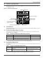
Figure 18 Operation and display panel . . . . . . . . . . . . . . . . . . . . . . . . . . . . . . . . . . . . . . . . . . . . . . . . . . . . . . 19
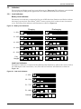
Figure 19 Battery level indicators. . . . . . . . . . . . . . . . . . . . . . . . . . . . . . . . . . . . . . . . . . . . . . . . . . . . . . . . . . . 20
Figure 20 Load level indicators . . . . . . . . . . . . . . . . . . . . . . . . . . . . . . . . . . . . . . . . . . . . . . . . . . . . . . . . . . . . . 20
Figure 21 Terminal block communication pin layout . . . . . . . . . . . . . . . . . . . . . . . . . . . . . . . . . . . . . . . . . . . 26
Figure 22 Removing the front bezel cover and battery door . . . . . . . . . . . . . . . . . . . . . . . . . . . . . . . . . . . . . . 29
Figure 23 Disconnecting the battery plug and battery receptacle (front view) . . . . . . . . . . . . . . . . . . . . . . . 29
Figure 24 Pull out the battery. . . . . . . . . . . . . . . . . . . . . . . . . . . . . . . . . . . . . . . . . . . . . . . . . . . . . . . . . . . . . . 29
Figure 25 Battery level indicator . . . . . . . . . . . . . . . . . . . . . . . . . . . . . . . . . . . . . . . . . . . . . . . . . . . . . . . . . . . 31
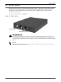
Figure 26 Battery cabinet
TABLES
Table 1 UPS models, power ratings . . . . . . . . . . . . . . . . . . . . . . . . . . . . . . . . . . . . . . . . . . . . . . . . . . . . . . . . 4
Table 2 Input circuit breaker specification . . . . . . . . . . . . . . . . . . . . . . . . . . . . . . . . . . . . . . . . . . . . . . . . . . 17
Table 3 Functions of On/Alarm Silence/Manual battery test button . . . . . . . . . . . . . . . . . . . . . . . . . . . . . 19
Table 4 Functions of Standby/Manual Bypass button . . . . . . . . . . . . . . . . . . . . . . . . . . . . . . . . . . . . . . . . 19
Table 5 UPS status indicators . . . . . . . . . . . . . . . . . . . . . . . . . . . . . . . . . . . . . . . . . . . . . . . . . . . . . . . . . . . 21
Table 6 Output voltage option . . . . . . . . . . . . . . . . . . . . . . . . . . . . . . . . . . . . . . . . . . . . . . . . . . . . . . . . . . . 25
Table 7 Replacement internal battery pack model number. . . . . . . . . . . . . . . . . . . . . . . . . . . . . . . . . . . . . 28
Table 8 Indicator descriptions . . . . . . . . . . . . . . . . . . . . . . . . . . . . . . . . . . . . . . . . . . . . . . . . . . . . . . . . . . . . 31
Table 9 Audible alarm description . . . . . . . . . . . . . . . . . . . . . . . . . . . . . . . . . . . . . . . . . . . . . . . . . . . . . . . . 32
Table 10 Troubleshooting . . . . . . . . . . . . . . . . . . . . . . . . . . . . . . . . . . . . . . . . . . . . . . . . . . . . . . . . . . . . . . . . 32
Table 11 Specifications of GXT3-500RT120 - GXT3-1000RT120 and GXT3-1000MT120 UPS . . . . . . . . . . 35
Table 12 Specifications of GXT3-1500RT120 - GXT3-3000RT120 and GXT3-3000RT208 UPS . . . . . . . . . 36
Table 13 Operating temperature parameters. . . . . . . . . . . . . . . . . . . . . . . . . . . . . . . . . . . . . . . . . . . . . . . . . 37
Table 14 Battery cabinet specifications . . . . . . . . . . . . . . . . . . . . . . . . . . . . . . . . . . . . . . . . . . . . . . . . . . . . . 37
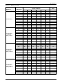
Table 15 Battery run times . . . . . . . . . . . . . . . . . . . . . . . . . . . . . . . . . . . . . . . . . . . . . . . . . . . . . . . . . . . . . . . 38

iv

1
IMPORTANT SAFETY PRECAUTIONS
SAVE THESE INSTRUCTIONS
This manual contains important safety instructions that must be followed during the installation and
maintenance of the UPS and batteries. Read this manual thoroughly before attempting to install or
operate this UPS.
UPS Safety Notes
This UPS contains no user-serviceable parts except the internal battery pack. The Off/Bypass
push button does not electrically isolate internal parts. Under no circumstances attempt to gain
internal access other than to replace the batteries due to risk of electric shock or burn. Do not
continue to use the UPS if the front panel indications are not in accordance with these operating
instructions or if the UPS performance alters in use. Refer all faults to your local dealer, Emerson
Network Power representative or Emerson Network Power Channel Support.
This UPS has an internal battery, and the output receptacles of the UPS may carry live voltage even
if the UPS is not connected to utility input power.
Before moving or rewiring this UPS, disconnect utility input power and the battery and make sure
that the UPS is completely shut down. Otherwise, the output terminal may carry live voltage,
presenting an electric shock hazard.
To ensure human safety and normal UPS operation, the UPS must be properly grounded before use.
When the UPS is connected to an IT power distribution system, a short-circuit protection device must
be installed on the neutral line.
Install and use the Liebert
®
GXT3
™
in the following environments:
• Temperature: 32°F - 104°F (0°C - 40°C), relative humidity: 0% ~ 95% non-condensing
• Out of direct sunlight
• Away from heat sources
• Stable surface, not subject to vibrations or shocks
• Away from dust and other particulates
• Away from corrosive substances, salts and flammable gases
Keep the air inlet and outlet of this UPS unobstructed. Poor ventilation will increase the internal
temperature of the UPS and can adversely affect the UPS and its batteries.
Keep liquid and foreign objects away from the UPS.
In case of fire, use a dry chemical fire extinguisher to put out the fire. Using a fluid fire extinguisher
may cause electric shock.
This UPS is not intended for use with life support and other designated critical devices. Maximum
load must not exceed that shown on the UPS rating label. This UPS is designed for data processing
equipment. If uncertain, consult your local dealer or Emerson representative.
This UPS is not for use in a computer room as defined in the standard for the Protection of Electronic
Computer/Data Processing Equipment, ANSI/NFPA 75.
The Liebert
®
GXT3-3000RT120
™
was tested under 30A branch circuit in accordance with the
National Electrical Code, ANSI/NFPA 70. To reduce the risk of fire, connect only to a circuit provided
with 30A maximum branch overcurrent protection.
!
WARNING
Observe all cautions and warnings in this manual. Failure to do so may result in serious
injury or death.
Refer all UPS and battery service to properly trained and qualified service personnel. Do not
attempt to service this product yourself.
Opening or removing the cover may expose you to lethal voltages within this unit even when
it is apparently not operating and the input wiring is disconnected from the electrical source.
Never work alone.

2
The Liebert
®
GXT3
™
-3000RT208 was tested under 20A branch circuit in accordance with the
National Electrical Code, ANSI/NFPA 70. To reduce the risk of fire, connect only to a circuit provided
with 20A maximum branch overcurrent protection.
Battery Safety
ELECTROMAGNETIC COMPATIBILITY—The Liebert GXT3 complies with the limits for a
CLASS A DIGITAL DEVICE, PURSUANT TO Part 15 of FCC rules. Operation is subject to the
following two conditions: (1) This device may not cause harmful interference and (2) this device must
accept any interference received, including interference that may cause undesired operation.
Operating this device in a residential area is likely to cause harmful interference that users must
correct at their own expense.
The Liebert GXT3 series complies with the requirements of EMC Directive 2004/108/EC and the
published technical standards. Continued compliance requires installation in accordance with these
instructions and use of accessories approved by Emerson.
Information for the Protection of the Environment
UPS Servicing: UPS makes use of components dangerous for the environment (electronic cards,
electronic components). The components removed must be taken to specialized collection and disposal
centers.
!
CAUTION
Do not dispose of batteries in a fire. The batteries may explode.
Do not open or mutilate the batteries. Released electrolyte is toxic and is harmful to skin and
eyes.
Dispose of used batteries according to the instructions.
!
CAUTION
A battery can present a risk of electrical shock and high short circuit current. The following
precautions should be observed when working on batteries:
• Remove watches, rings and other metal objects.
• Use tools with insulated handles.
• Wear rubber gloves and boots.
• Do not lay tools or metal parts on top of batteries.
• Disconnect charging source prior to connecting or disconnecting battery terminals.
• Determine if the battery is inadvertently grounded. If it is inadvertently grounded, remove
the source of the ground. Contact with any part of a grounded battery can result in electri-
cal shock. The likelihood of such shock will be reduced if grounds are removed during
installation and maintenance (applicable to a UPS and a remote battery supply not having
a grounded supply circuit).

3
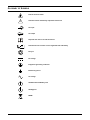
GLOSSARY OF SYMBOLS
Risk of electrical shock
Indicates caution followed by important instructions
AC input
AC output
Requests the user to consult the manual
Indicates the unit contains a valve-regulated lead acid battery
Recycle
DC voltage
Equipment grounding conductor
Bonded to ground
AC voltage
ON/Alarm Silence/Battery Test
OFF/Bypass
WEEE
!
i
PbH2SO4
-
+
R

Product Description
4
1.0 PRODUCT DESCRIPTION
The Liebert
®
GXT3
™
is a compact, online uninterruptible power system (UPS) that continuously
conditions and regulates its output voltage. The Liebert GXT3 is designed to supply microcomputers
and other sensitive equipment with clean sine wave input power.
Upon generation, AC power is clean and stable. However, during transmission and distribution it is
subject to voltage sags, spikes and complete failure that may interrupt computer operations, cause
data loss and damage equipment.
The Liebert GXT3 protects equipment from these disturbances. The Liebert GXT3 continuously
charges its batteries from utility power, enabling it to supply power to connected loads, even when
utility power fails.
This sections describes the UPS, its features, models, appearance and components, operating
principles and operating mode.
1.1 Features
• Intelligent battery management to extend the battery life
• Operation and display panel with LED for monitoring load percentage and battery capacity inde-
pendently
• Flexible network management with Liebert MultiLink
™
software
• Fan fault self-inspection and automated diagnostic function
• Intelligent fan operation, automatically changing rotation speed depending on system require-
ments, to decrease power consumption and noise
• Input circuit breaker to ease recovery from overloads
• Safety approval from UL and cUL
• Communication options: USB port, Liebert IntelliSlot
®
port and terminal block communication
• Dry contacts for remote monitoring
• Input power factor greater than0.99
• Output voltage selection function
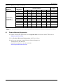
1.2 Available Models
Eight UPS models are available.
Table 1 UPS models, power ratings
Model Nominal Power Rating
GXT3-500RT120 500VA/450W
GXT3-700RT120 700VA/630W
GXT3-1000RT120 1000VA/900W
GXT3-1000MT120 1000VA/900W, minitower
GXT3-1500RT120 1500VA/1350W
GXT3-2000RT120 2000VA/1800W
GXT3-3000RT120 3000VA/2700W
GXT3-3000RT208 3000VA/2700W

Product Description
5
1.3 Appearance and Components
1.3.1 Front Panel and Controls
The Liebert
®
GXT3
™
rack/tower and minitower models in various power ratings have the same
general appearance, controls and features (see Figure 1). The various rack/tower and minitower
models differ largely in the type of receptacles each has.
Figure 1 Liebert GXT3 rack/tower models—front view
The Liebert GXT3-1000MT120
™
has the same controls and features in a minitower arrangement (see
Figure 2).
Figure 2 Liebert GXT3 minitower—front view
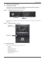
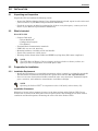
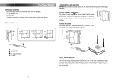
1.3.2 Rear Panel Features
The rear panel of the Liebert GXT3 has these features:
•USB port
• Cooling fan
• Power output receptacles
• Input circuit breaker
• Liebert IntelliSlot
®
port
• Communication terminal block
• Input power cable
Operation and
Display Panel
Ventilation Slots
Operation and
Display Panel
Ventilation Slots

Product Description
6
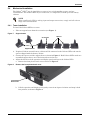
Figure 3 Liebert
®
GXT3
™
120V rack/tower models—rear panel components
Input Power Plug
and Cable 5-15P
External
Battery
Connector
Terminal Block
Communication
USB Port
Input Circuit
Breaker
Output
Receptacles,
5-15R
500VA, 700VA, 1000VA, 1500VA Models
Input Power Plug
and Cable, 5-20P
External
Battery
Connector
USB Port
Input Circuit
Breaker
Output
Receptacles,
5-15/20R
2000VA Model
Input Power Plug
and Cable, L5-30P
USB Port
External
Battery
Connector
Input Circuit
Breaker
Output Receptacles,
5-15/20R
Output
Circuit
Breakers
3000VA Model
Liebert
IntelliSlot
Port
Liebert
IntelliSlot
Port
Liebert
IntelliSlot
Port
Terminal Block
Communication
Terminal Block
Communication
Output Receptacle,
L5-30R
Cooling
Fan
Cooling
Fan
Cooling
Fan

Product Description
7
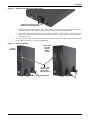
Figure 4 Liebert
®
GXT3
™
208V rack/tower models—rear panel components
Figure 5 Liebert GXT3-1000MT120
™
—rear panel components
3000VA Model
Input Power Plug
and Cable, L6-20P
External
Battery
Connector
USB Port
Cooling
Fan
Input Circuit
Breaker
Output
Receptacle,
L6-20R
Output
Circuit
Breakers
Liebert
IntelliSlot
Port
Terminal Block
Communication
Output
Receptacles,
L6-15R
Liebert IntelliSlot Port
1000VA Model
Input Power Plug
and Cable, 5-15P
USB Port
Cooling Fan
Input Circuit
Breaker
Output
Receptacles,
5-15R
Terminal Block
Communication

Product Description
8
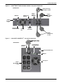
1.4 Major Components
The operating principle of the UPS is illustrated in Figure 6.
Figure 6 Operating principle diagram
The UPS is composed of utility input, TVSS and EMI/RFI filters, rectifier/PFC, inverter, battery
charger, DC-to-DC converter, battery, dynamic bypass and UPS output.
Transient Voltage Surge Suppression (TVSS) and EMI/RFI Filters
The Liebert
®
GXT3
™
has surge protection and filters that protect the connected load from power
surges, electromagnetic interference (EMI) and radio frequency interference (RFI). These features
can minimize any surges or interference present in the utility power. The filters also prevent surges
or interference generated by the UPS from adversely affecting devices connected on the same branch
as the UPS.
Rectifier/Power Factor Correction (PFC) Circuit
In normal operation, the Liebert GXT3’s rectifier/power factor correction (PFC) circuit converts utility
power to regulated DC power for use by the inverter while ensuring that the wave shape of the input
current used by the UPS is near ideal. Extracting this sinewave input current achieves two objectives:
• Efficient power use by the UPS
• Reduced reflected harmonics
This results in cleaner power being available to other devices in the building not being protected by
the Liebert GXT3.
Inverter
In normal operation, the Liebert GXT3’s inverter utilizes the DC output of the PFC to produce
precise, regulated sine wave AC power. When utility power fails, the inverter receives DC power from
the DC-to-DC Converter. In either operation mode, the UPS inverter is online, continuously
generating clean, precise, regulated AC output power.
L1
Dynamic
Bypass
Input
DC-to-DC
Converter
Rectifier /
PFC
Inverter
Battery
Battery
Charger
L1
TVSS & EMI/
RFI Filters
L2/N
Output
L2/N
GG

Product Description
9
Battery Charger
The battery charger utilizes energy from the utility power and precisely regulates it to continuously
float charge the batteries. The batteries are being charged whenever the Liebert
®
GXT3
™
is plugged
in, even when the UPS is not turned On.
DC-to-DC Converter
The DC-to-DC converter raises the DC voltage from the battery to the optimum operating voltage for
the inverter. This allows the inverter to operate continuously at its optimum efficiency and voltage,
thus increasing reliability.
Battery
The Liebert GXT3 uses valve-regulated, nonspillable, lead acid batteries. To maintain battery design
life, operate the Liebert GXT3 in an ambient temperature of 32°F to 77°F (0°C to 25°C).
Optional external battery cabinets are available to extend battery run times.
Dynamic Bypass
The Liebert GXT3 provides an alternate path for utility power to the connected loads in the unlikely
event of a UPS malfunction. Should the Liebert GXT3 have an overload, overtemperature or UPS
failure condition, the UPS automatically transfers the connected loads to bypass.
1.5 Operating Mode
The UPS operation modes include: Utility (AC) mode, bypass mode, battery mode, battery recharge
mode and frequency converter mode.
For the descriptions of indicators and control buttons in this section, refer to 3.0 - Controls and
Indicators.
1.5.1 Utility (AC) Mode
During Utility (AC) Mode, utility power provides energy to the Liebert GXT3. The filters, PFC circuit
and the inverter process this power to provide computer-grade power to connected loads. Meanwhile,
the UPS maintains the batteries in a fully charged state.
1.5.2 Manual Bypass Mode
Manual Bypass Mode occurs when the Standby/Manual bypass button is pressed and held for about
2 seconds while the Liebert GXT3 is in Utility (AC) Mode. Bypass operation is indicated by an audible
alarm and illuminated amber bypass indicator (If other indicators are illuminated, refer to 7.0 -
Troubleshooting). During manual bypass mode, utility power bypasses the inverter and provides
energy to the connected load.
NOTICE
Turning Off the UPS in bypass mode will result in loss of output power and dropped loads.
NOTE
The bypass power path does not protect the connected loads from disturbances on the utility.

Product Description
10
1.5.3 Battery Mode
The Liebert
®
GXT3
™
enters Battery Mode when utility power fails or is outside acceptable values.
The battery system supplies power through the DC-to-DC converter to the inverter to generate clean
AC power for the connected loads.
When the Liebert GXT3 enters Battery Mode, the UPS sounds a half-second beep at 10-second
intervals. When approximately 2 minutes of run time remains, the beeps sound every 5 seconds to
warn that the battery is getting low (this Low Battery Warning is user-configurable).
In Battery Mode, the AC Input indicator goes Off and the Battery Level indicators illuminate. Each
battery level indicator represents a 20% capacity level. As capacity decreases, fewer indicators remain
illuminated. Refer to 7.0 - Troubleshooting.
For approximate battery run times, refer to 9.0 - Specifications.
NOTICE
Turning Off the Liebert GXT3 when it is in Battery Mode will result in loss of output power.
If the UPS is turned Off manually, it must be manually restarted after utility power returns.
If the UPS is turned Off by a communication signal or because the batteries are depleted, it
will operate as selected in the configuration program for Auto-Restart (Refer to 5.2.1 -
Configuration Program).
1.5.4 Battery Recharge Mode
Once utility power is applied to the Liebert GXT3, the Battery Charger begins charging the batteries.
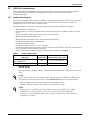
1.5.5 Frequency Converter Mode
All models of the Liebert GXT3 are capable of frequency conversion. Frequency Conversion Mode can
be selected using the configuration program. Allowable frequency operating modes include:
• Auto Sensing - 50Hz or 60Hz – Bypass Enabled
• Auto Sensing - 50Hz or 60Hz – Bypass Disabled
• Frequency Converter - 50Hz – Bypass Disabled
• Frequency Converter - 60Hz – Bypass Disabled
The default for all models of the Liebert GXT3 is “Auto Sensing - 50Hz or 60Hz – Bypass Enabled.”

Installation
11
2.0 INSTALLATION
2.1 Unpacking and Inspection
Unpack the UPS and conduct the following checks:
• Inspect the UPS for shipping damage. If any shipping damage is found, report it to the carrier and
your local dealer or your Emerson representative immediately.
• Check the accessories included in packaging list. If there is any discrepancy, contact your local
dealer or your Emerson representative immediately.
2.2 What’s Included
With GXT3 UPS
• Compact Disk with:
• Liebert MultiLink
®
• Configuration Program
• User Manual
• Terminal Block Communication terminals
• USB Cable: one, 6-1/2 ft. (2m) long
• Mounting hardware, including screws and handles
• Plastic tower stand sets: 2 (four pieces)
• Warnings, Safety Instructions booklet and WEEE recycling sheet (ISO 14001 compliance)
2.3 Preparation for Installation
2.3.1 Installation Environment
• Install the UPS indoors in a controlled environment, where it cannot be accidentally turned Off.
The installation environment should meet the specifications listed in 9.0 - Specifications).
• Place it in an area of unrestricted airflow around the unit, away from water, flammable liquids,
gases, corrosives, and conductive contaminants. Avoid direct sunlight.
Installation Clearances
Maintain at least 4 inches (100mm) clearance in the front and rear of the Liebert GXT3. Do not
obstruct the air inlets on the front panel and rear panel of the UPS; blocking the air inlets reduces
ventilation and heat dissipation, shortening the service life of the Liebert GXT3.
NOTE
The GXT3 External Battery Cabinet shipping package includes one battery cabinet, two
spacers for tower configuration and one DC power cable.
NOTE
Operating the Liebert GXT3
™
in temperatures above 77°F (25°C) reduces battery life.

Installation
12
2.4 Mechanical Installation
The Liebert
®
GXT3
™
may be installed as a tower or in a rack, depending on space and use
considerations. The Liebert GXT3 may be used alone, as a single UPS, or with up to four battery
cabinets.
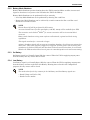
2.4.1 Tower Installation
To install the Liebert GXT3 as a tower:
1. Take out support bases from the accessories (see Figure 7).
Figure 7 Support bases
2. If optional Liebert external battery cabinets will be connected to the Liebert GXT3, take out the
spacers shipped with the battery cabinet.
3. Connect the spacers and the support bases as shown in Figure 7. Each Liebert GXT3 needs two
assembled support bases, one in the front and one in the rear.
4. Adjust the direction of the operation and display panel and logo on the Liebert GXT3.
a. Remove the front plastic bezel cover as shown in Figure 8.
Figure 8 Remove the front plastic bezel cover
b. Pull the operation and display panel gently, rotate it 90 degrees clockwise and snap it back
into position, as shown in Figure 9.
NOTE
When installing the UPS or making input and output connections, comply with all relevant
safety codes and standards
Support Bases
Spacers
Connectors
Front Plastic
Bezel Cover

Installation
13
Figure 9 Rotate the operation and display panel
c. Pull the logo on the front plastic bezel cover gently, rotate it 90 degrees clockwise and snap it
back into position. The rotated front plastic bezel cover is shown in Figure 10.
d. Replace the front plastic bezel cover on the Liebert
®
GXT3
™
. At this point, the UPS operation
and display panel and logo have been rotated 90 degrees clockwise, which provides upright
viewing for users.
5. Place the Liebert GXT3 and any battery cabinets on the support bases. Each Liebert GXT3 needs
two support assemblies, as shown in Figure 10.
Figure 10 Tower installation
Operation and Display Panel
Rotated Clockwise 90 Degrees
Operation and
Display Panel
Rotated for
Tower Operation
Support Bases
Liebert
GXT3 UPS
Liebert GXT3
UPS and
External
Battery
Cabinet

Installation
14
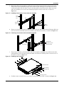
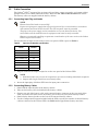
2.4.2 Rack Installation
To install a Liebert GXT3 rack/tower UPS in a rack:
1. Unpack the two slide rails assemblies and mounting hardware from the rack-mounting kit
(P/N: RMKIT18-32).
Slide rail assembly includes inner member and front and rear members. They are interchange-
able between left-hand or right-hand. Mounting hardware includes M4 screws and M5 screws.
2. Remove inner member of each slide rail assembly by extending it to its outermost position,
depressing the retaining latch and then pulling inner member from slide rail assembly (see
Figure 11).
Figure 11 Pulling inner member from each slide rail assembly
3. Determine the Liebert GXT3’s mounting position inside the racks vertical rails.
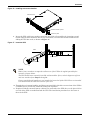
4. Attach the rear member of each slide rail assembly to the rack’s rails with two factory-supplied
M5 screws (see Figure 12).
Figure 12 Installing rear member of each slide rail assembly
NOTE
• When the Liebert
®
GXT3
™
is installed in a rack, it must be supported by a shelf, fixed
rails or slide rails on each side. The factory-supplied rack mount handles cannot sup-
port the weight of the UPS. They are used to move the UPS into and out of the rack and
attach the UPS to the rack.
• Mounting hardware and slide rails are sold separately. Contact your local Emerson
representative for these options and any assistance.
• GXT3-1000MT120 cannot be installed in a rack. The unit is a minitower only.
!
CAUTION
Reduce the risk of tipping the rack by installing the Liebert GXT3 as low as possible in the
rack.
Slide rail assembly
Retaining latch
Inner member
P
u
l
l
o
u
t
M5 screw (4 pcs)
Vertical pole
Rear member
Front member
Page is loading ...
Page is loading ...
Page is loading ...
Page is loading ...
Page is loading ...
Page is loading ...
Page is loading ...
Page is loading ...
Page is loading ...
Page is loading ...
Page is loading ...
Page is loading ...
Page is loading ...
Page is loading ...
Page is loading ...
Page is loading ...
Page is loading ...
Page is loading ...
Page is loading ...
Page is loading ...
Page is loading ...
Page is loading ...
Page is loading ...
Page is loading ...
Page is loading ...
Page is loading ...
Page is loading ...
Page is loading ...
-
 1
1
-
 2
2
-
 3
3
-
 4
4
-
 5
5
-
 6
6
-
 7
7
-
 8
8
-
 9
9
-
 10
10
-
 11
11
-
 12
12
-
 13
13
-
 14
14
-
 15
15
-
 16
16
-
 17
17
-
 18
18
-
 19
19
-
 20
20
-
 21
21
-
 22
22
-
 23
23
-
 24
24
-
 25
25
-
 26
26
-
 27
27
-
 28
28
-
 29
29
-
 30
30
-
 31
31
-
 32
32
-
 33
33
-
 34
34
-
 35
35
-
 36
36
-
 37
37
-
 38
38
-
 39
39
-
 40
40
-
 41
41
-
 42
42
-
 43
43
-
 44
44
-
 45
45
-
 46
46
-
 47
47
-
 48
48


Emerson 3000VA User manual
- Type
- User manual
- This manual is also suitable for
Ask a question and I''ll find the answer in the document
Finding information in a document is now easier with AI
Related papers
-
Emerson Liebert GXT3 Series User manual
-
-
-
-
SolaHD MultiLINK Owner's manual
-
-
Liebert GXT3 User manual
-
-
-
Other documents
-
Avocent GXT3-3000RT120 Datasheet
-
Liebert GXT3 RT120 Quick start guide
-
 PowerWalker DC SecureAdapter 12V Owner's manual
-
-
Compaq dc5000 - Microtower PC Using Instructions
-
APC SURT011 User manual
-
 Leonics Ultimate-X 3000VA User manual
-
-
-

