Vello FTA-TTL-C User manual

Category
Supplementary music equipment
Type
User manual

This manual is also suitable for

FREEWAVE
AVIATOR
TTL FLASH REMOTE SYSTEM
USER MANUAL
2
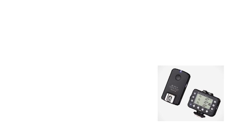
Thank you for choosing the Vello FreeWave
Aviator System. The FreeWave Aviator
is a professional solution for wirelessly
controlling o-camera TTL-capable
flashes while retaining full TTL capability.
The FreeWave Aviator System is an ideal
tool for photographers on every level.
The Aviator gives you the ability to fine
tune your lighting and help you match
your final shot to your creative vision.
The Vello FreeWave Aviator allows for
an impressive range of wireless control.
Supporting up to 16 channels, flashes can
be arranged in three groups, which can
each be set to TTL or Manual mode. The
TTL EV compensation, manual power,
and zoom levels for each group can be
INTRODUCTION
changed separately, and groups can also be
controlled with ratio-based adjustments.
This allows the flexibility to be creative
with dierent lighting treatments and
eects. You can instantly raise and lower
power levels on select lights, or use the
zoom control to change the tone and shape
of the lighting for exciting new looks.
With its multiple groups feature, you can
easily configure up to three dierent light
groups, which can be triggered individually
or simultaneously, for a total of seven
dierent combinations. (Simultaneous
triggering of multiple flash groups requires
additional FreeWave Aviator Receivers
or Transceivers, available separately.)
The FreeWave Aviator does not require
line-of-sight positioning, since its radio
waves pass through and around objects,
such as walls, windows, and floors. It also
functions in all lighting conditions including
bright daylight or direct sunshine.
3
TABLE OF CONTENTS
Contents ............................................................. 4
Key Features ....................................................... 5
Precautions ......................................................... 6
Overview ............................................................ 8
Before You Begin ............................................. 10
Compatible Devices ....................................... 10
Mounting/Turning on the Transceiver ........ 11
Mounting the Receiver................................... 12
Mounting a Hot-Shoe Flash to a
Receiver/Transceiver ...................................... 13
Using Studio Flashes with a Receiver or
Transceiver ....................................................... 14
About TTL ........................................................ 15
Setting Channels.............................................. 16
Adjusting Master/Slave Mode
on the Transceiver .......................................... 17
Setting Flash Groups ...................................... 18
Adjusting a Flash Groups
TTL Power (EV) .............................................. 20
Adjusting a Flash Groups Zoom ................. 21
Using TTL Ratio Adjustment Modes .......... 22
Changing a Flash Group's Power Mode ..... 24
Using High Speed Sync/Second Curtain Sync
Modes ................................................................ 25
Setting Auto-Focus Assist
(Nikon Only) .................................................... 27
Additional Features ........................................ 28
Resetting the Transceiver to Factory
Default Settings ............................................... 29
Specifications ................................................... 30
Troubleshooting .............................................. 31
FCC Compliance............................................. 31
Transceiver Kit
Receiver Kit
4
Transceiver
Transceiver
Lanyard
3.5 mm to 3.5 mm cable
3.5 mm to 1/4˝ mono-plug cable
Hot-shoe protector
2 × AA batteries
User manual
CONTENTS
Receiver
Receiver
Lanyard
3.5 mm to 3.5 mm cable
3.5 mm to 1/4˝ Mono-plug cable
Hot-shoe protector
Adhesive backed accessory shoe
Hot-shoe locknut
2 × AA batteries
User manual
5
Wireless TTL (Through-the-Lens):
makes full use of your flashes’
built-in TTL technology
16 Channels (2.4 GHz Radio):
allow the setting of dierent
channels to avoid interference
Three Flash Groups:
enable configuration of dierent flash
groups with individual settings
Master/Slave Function: enables the
Transceiver to be used as either
a Master (Transmitter) on your
camera or as a Slave (Receiver)
with a flash attached
KEY FEATURES
TTL or Manual Mode: remotely
sets your flash to TTL or Manual
mode and can adjust power levels
TTL Exposure Compensation: enables
fine tuning of TTL exposure by +/− 3 EV
High Speed Sync:
allows flash synchronization
up to 1⁄8000 of a second
Regular or Second Curtain Sync:
allows you to create special
eects and “after blur” images
Flash Zoom Control: remotely sets
the zoom on all compatible flashes
Additional Lighting Options:
can trigger Studio Lights together
with your hot-shoe flashes
Backlit Digital Display: allows easy
viewing and changing of settings in all
lighting conditions on the Transceiver
Threaded PC-Sync Port:
can be used for a more secure
connection with a Receiver
TTL Hot Shoe: allows you to use a
TTL flash on-camera (pass through)
Battery Indicator: displays battery
life on the Transceiver
6
PRECAUTIONS
Please read full manual before using
device.
Do not disassemble or modify. Failure to
observe this precaution could result in
electric shock or product malfunction.
Should the product break open due to
accidental damage, remove the batteries
and send it to an authorized repair
center.
Keep dry. Do not handle with wet
hands, immerse in water, or expose to
rain or snow. Failure to observe this
precaution could result in fire or cause
electric shock.
Do not use in the presence of flammable
gases. Failure to observe this precaution
could result in fire or explosion.
Keep out of the reach of children. This
product contains small parts that may
pose a choking hazard. Should a child
swallow any part of this product, consult
a physician immediately.
Turn o immediately should a
malfunction occur. Should smoke or any
unusual smell come from this product,
shut it o and remove the batteries
immediately. Send it to an authorized
repair facility for service. Continued use
may result in damage or physical injury.
Do not expose to high temperature.
Do not leave product in a closed vehicle
in the sun or other area subject to
extremely high temperature. Failure to
observe this precaution could result
in fire or damage to casing or internal
parts.
Observe precautions when handling
batteries. Batteries may leak or explode
if improperly handled. Please observe
the following precautions when using
batteries with this product.
Use only batteries listed in this manual.
Do not mix new and old batteries or
dierent brands or types of batteries.
7
Read and follow all warnings and
instructions provided by the battery
manufacturer.
Do not attempt to short-circuit or
disassemble batteries.
Do not put batteries in a fire, or apply
direct heat to them.
Do not attempt to install batteries in
the reverse direction.
Batteries may leak when fully discharged.
To avoid damage to the product, be sure
to remove the batteries if the product
will not be used for an extended period
of time or if the battery power is low.
Should fluid from damaged batteries
come into contact with skin or clothing,
rinse immediately with fresh water.
Pictures are for illustration only.
Front Right
Back Left
1
11
2
3
8
13
4 7
9
14
5 6
10
15
12
8
OVERVIEW
Transceiver
1. LCD Display Screen
2. Group Settings Buttons (A,B, and C)
3. LED Indicator
4. Test Button
5. Menu Button
6. Option Button
7. Flash Sync Mode Button
8. Select Button
9. + and − Buttons
10. TTL-Dedicated Hot Shoe
11. Battery Compartment
12. Locking Wheel
13. Power Switch
14. 3.5 mm Sync Output Port
15. USB Port
To p Left
Bottom Right
Front
1
6
11
2
7
3
8
4
9
5
10 12
9
Receiver
1. LED Indicator
2. Test Button
3. TTL-Dedicated Hot Shoe
4. Battery Compartment
5. 1/4˝-20 Lightstand Socket
6. Channel Switch
7. Power Switch
8. Threaded PC Sync Output Port
9. Group Switch
10. USB Port
11. 3.5 mm Sync Output Port
12. Lanyard Mount
10
Installing the Batteries
The Aviator Transceiver and Receiver units
each require two AA batteries to operate.
To install, open the battery compartment
door and insert the batteries as
indicated by the polarity icons in
the compartment. Once installed,
close the compartment door.
BEFORE YOU BEGIN
The Vello FreeWave Aviator is available
in models for both Nikon i-TTL and
Canon E-TTL cameras. The Nikon and
Canon models are each compatible
with the respective company’s TTL
(Through-The-Lens) technology.
To make full use of the Aviator system,
we recommend using TTL-capable hot-
shoe flashes that are fully compatible
with your cameras TTL system.
FreeWave Aviator Transceivers and
Receivers do not provide high-voltage
sync protection, and they are not
recommended for use with flash units that
have a trigger voltage of more than 6V.
COMPATIBLE DEVICES
11
1. With your camera and Transceiver O,
loosen the Transceiver’s locking ring.
2. Insert the Transceiver’s hot shoe on
your camera's hot-shoe mount with the
LCD panel facing the rear of the camera.
3. Tighten the Transceiver's locking ring.
4. Turn on the Camera and then slide the
Transceiver's Power Switch to On.
5. Slide to O position to turn the
Transceiver o.
MOUNTING/TURNING ON THE TRANSCEIVER
Note: the Aviator Transceiver can also be mounted on any hot-shoe or cold-shoe compatible stand.
Note: make sure that your Master
Transceiver and all Receiver units and Slaves
are set to the same Channel before use.
12
1. With your Receiver and flash O, mount
the Receiver to your 1/4˝-20 light stand
or accessory stand. Take care not to
overtighten the Receiver.
2. Slide the Group Switch to A, B, or C to
select the desired Group. (The Group
D setting on the Receiver is for factory
calibration only and is not available
for use.)
3. Slide the Channel Switch to 1, 2,
3, or Auto. (Auto” is equal to the
Transceiver's Channel “4”.)
MOUNTING THE RECEIVER
Note: make sure that all your FreeWave Aviator units are set to the same channel before use.
13
1. Make sure the flash and Receiver or
Transceiver are turned O.
2. Switch the flashs locking switch to the
unlocked position.
3. Insert the flash’s hot-shoe foot into
the Receiver or Transceiver’s hot-shoe
mount.
4. Switch the flashs locking switch to the
locked position.
MOUNTING A HOT-SHOE FLASH TO A RECEIVER/TRANSCEIVER
5. Turn on the flash.
6. Your flash must be in TTL mode in order
to function properly in all modes with
the FreeWave Aviator. (See your flash’s
manual for assistance.)
7. Turn on your Aviator Receiver or
Transceiver by moving the switch to the
On position.
14
For more complex lighting needs, the
FreeWave Aviator can also trigger studio
flashes independently or alongside hot-shoe
flashes. (Note that TTL compatibility is
only available for TTL-capable flashes.)
Both the Aviator Receiver and Transceiver
have 3.5 mm Sync Ports, and the Receiver
also has a PC Sync Port which allows you to
connect a sync cable to your studio flashes.
Note: the PC Sync Port will also
accept a PC locking cable.
USING STUDIO FLASHES WITH A RECEIVER OR TRANSCEIVER
Connecting with a 3.5 mm Cable
1. Plug the 3.5 mm cable into the Receiver
or Transceiver’s Sync Port.
2. Plug the other end of the cable into the
studio flash's 3.5 mm jack.
3. If your studio flash has a 1/4˝ monoplug
jack, you will need to use the included
3.5 mm to 1/4˝ monoplug cable.
Connecting with a PC Sync Cable
1. Using a PC Sync to 3.5 mm cable (not
included), plug the PC Sync end into the
Receiver's PC Sync port.
2. Plug the 3.5 mm end of the cable into
the studio flash's 3.5 mm jack.
3. If your studio flash has a 1/4˝ monoplug
jack, you will need to use a PC Sync to
1/4˝ monoplug cable (not included).
15
The FreeWave Aviator automatically
sets the appropriate flash level using
your cameras through-the-lens (TTL)
metering system data, calculating the
correct power for all communicating
TTL compatible flashes.
ABOUT TTL
Main TTL Adjustment Screen
The startup or default screen for the
Aviator Transceiver is called the TTL
Screen. Many of the instructions start
out from the TTL Screen, so it will be
helpful to remember how to return to it.
To return to the TTL Screen while in
Master mode (see page 17), simply
press the Option button once or
twice until the screen appears. (If the
device is in Slave mode, you will first
have to return to Master mode.)
Once set, the Aviator Transceiver
retains all changes made to its settings,
even after the device is turned o.
Note: see page 29 for resetting the
Transceiver to factory default settings.
Channel
16
Setting an Aviator
Transceiver’s Channel
To set the desired Channel,
do the following:
1. From the TTL Screen or the Slave Mode
screen, press Menu to enter Channel
Select.
2. Use the + and buttons to select the
desired channel from 1-16 (channels
5-16 are only available when using two
Aviator Transceiver units).
3. Press Select to apply the setting.
Setting an Aviator Receiver’s Channel
While the Receiver is O, slide the Channel
switch to the desired Channel (1, 2, 3
or Auto). Then turn the Receiver on.
Note: “Auto” is equal to the
Transceiver's Channel “4”
Note: all devices must be set to the same channel for the system to function properly.
SETTING CHANNELS
Master
Mode
17
ADJUSTING MASTER/SLAVE MODE ON THE TRANSCEIVER
Using the FreeWave Aviator System
requires at least two units: one Transceiver
set to Master mode and either a Receiver
or a second Transceiver set to Slave mode.
The Transceiver you are using to control
your lighting must be set to Master mode.
To set a Transceiver to either Master
or Slave mode, do the following:
1. From the TTL Screen, press Menu
twice. The device’s current mode will
start blinking.
2. Toggle between Master and Slave mode
using the + and buttons.
3. Press Select when the desired mode is
displayed to apply the setting.
Note: when using a flash in the hot shoe atop
a Transceiver set to Master mode, the flash
will operate as a 4th TTL Group in “fully”
automatic mode. Adjustments are limited
to “fully” TTL (i.e. TTL EV Adjustments are
not available) or Manual power settings.
Note: when a Transceiver is set to Slave mode, the Flash/Test button will not function.
Slave
Mode
Group
A
Flash Group
Mode Setting
18
Setting Flash Groups on the
Aviator Transceiver in Master Mode
The Aviator Transceiver allows individual
control of flash settings for groups A, B and
C. It can also fire all groups simultaneously.
To set the mode of a particular
flash group, do the following:
1. Press the desired group to toggle
through the modes, ( between TTL,
Manual and OFF)
Setting Flash Groups on the
Aviator Transceiver in Slave Mode
When the Transceiver is in Slave mode, set
the desired group by pressing A, B, or C.
SETTING FLASH GROUPS
19
Setting the Group on the
Aviator Receiver
Slide the Group switch on the
Aviator Receiver to the desired
Group (either A, B, or C).
To assign multiple Receivers to the same
flash group, simply select the same group
letter for each Receiver in the flash group.
Note: you can combine studio lights
and speedlights within the same flash
group. (Be aware of the independent
recycling time of each flash to ensure
all flash units are ready to fire).
Note: the Group D setting is reserved for
factory calibration and is not available for use.
TTL EV
Setting
20
Using a Transceiver in Master mode:
1. From the TTL Screen, press Select. The
screen will start flashing.
2. Press A, B, or C to select the desired
flash group. The selected group will
start flashing.
3. Use the + and buttons to set the EV
(exposure) in TTL mode.
4. Press Select twice when done to apply
the settings.
5. Press /Test to confirm settings.
ADJUSTING A FLASH GROUP’S TTL POWER (EV)
Note: /Test fires a test flash on all
connected hot-shoe lights and studio lights.
It is advisable to always test fire your flashes
after making changes to confirm your settings.
  • Page 1 1
  • Page 2 2
  • Page 3 3
  • Page 4 4
  • Page 5 5
  • Page 6 6
  • Page 7 7
  • Page 8 8
  • Page 9 9
  • Page 10 10
  • Page 11 11
  • Page 12 12
  • Page 13 13
  • Page 14 14
  • Page 15 15
  • Page 16 16
  • Page 17 17
  • Page 18 18
  • Page 19 19
  • Page 20 20
  • Page 21 21
  • Page 22 22
  • Page 23 23
  • Page 24 24
  • Page 25 25
  • Page 26 26
  • Page 27 27
  • Page 28 28
  • Page 29 29
  • Page 30 30
  • Page 31 31
  • Page 32 32

Vello FTA-TTL-C User manual

Category
Supplementary music equipment
Type
User manual
This manual is also suitable for

Ask a question and I''ll find the answer in the document

Finding information in a document is now easier with AI