Page is loading ...

Installation
®
Instr ct
36" Glass Canopg
Chimneg Vent Hood
ZV900
49-80328-3 ]
Monogram°

SafetyInformation
BEFORE YOU BEGIN
Read these instructions completely and carefully.
" IMPORTANT- Sovetheseinstructions for
Iocol inspector's use.
"IMPORTANT- Observeollgoverningcodes
ond ordinonces.
, Note to Installer - Besure to leove these
instructions with the Consumer.
. Note to Consumer - Keep these instructions
with gout Owner's Monuol for future reference.
. Skill Level -Instollotion of this opplionce requires
bosic mechonicol ond electricol skills.
. Completion Time - 1 to 3 Hours.
. Proper instollation isthe responsibilitg of the instoller.
Product foilure due to improper instollotion is not
covered under the worrontg.
For Monogram local service in gour area, call
1.800.444.1845.
For Monogram service in Canada, call 1.888.880.3030
For Monogram Parts and Accessories, call
1.800.626.2002.
ACAUTION:
Due to the weight ond size of these vent hoods ond
to reduce the risk of personol injurg or domoge to the
product, TWO PEOPLEAREREQUIREDFORPROPER
INSTALLATION.
PRUDENCE :
/_couse du poids et de Iotoille de ces hottes et pour
reduire le risque de blessures et de dommoges, IL
FAUT DEU×PERSONNESPOUR FAIREL'INSTALLATION
CORRECTEMENT.
WARNING:
To reduce the risk of fire or electricol shock, do not
use this ronge hood with ong externol solid-stote speed
control device. Ang such olterotion from originol foctorg
wiring could result in domoge to the unit ond/or creote
on electricol sofetg hozord.
AVERTISSEMENT :
Pour r_duire le risque d'incendie ou de choc 61ectrique,
il ne lout pos utiliser cette hotte ovec un rGguloteur de
vitesse 61ectronique externe. Toute modificotion de ce
tgpe du bronchement d'usine peute endommoger
I'opporeil ou crGer un risque de choc 61ectrique.
TO REDUCETHE RISKOFFIRE,USEONLY METAL
DUCTWORK.
AIA#^OklIMr_
JllVV_I_'_I_I_III_I_I: TO REDUCE THE RISKOF
FIRE,ELECTRICALSHOCK OR INJURYTO PERSONS,
OBSERVE THE FOLLOWING:
A. Use thisunitonlginthemonner intendedbg the
monufocturer.Ifgou hoveong questions,contoctthe
monufocturer.
B. Beforeservicingorcleoningunit,switchpower offot
theserviceponelond lockserviceponeltoprevent
power from beingswitchedon occidentollg.Ifthe
serviceponelconnotbe locked,fosteno togor
prominentworningIobeltotheponel.
AAVERTISSEMENT :
POUR REDUIRE LE RISQUE D'INCENDIE, DE CHOC
I_LECTRIQUE OU DE BLESSURES, IL FAUT OBSERVER LES
REGLESSUIVANTES :
A. Utiliser cet opporeil uniquement de Io moniGre
prGvue pot le fobricont. Encos de question, consulter
le fobricont.
B. Avont toute intervention ou nettogoge, couper
I'olimentotion 61ectriqueou disjoncteur et verrouiller
le ponneou du disjoncteur pour 6viter Io mise
sous tension occidentelle. S'il n'est pos possible de
verrouiller le ponneou du disconcteur, ottocher un
plocord ou une 6tiquette trGsvisible ou ponneou.
. For generol ventiloting use onlg. Do not use to
exhoust hozordous or explosive moteriols or vopors.
. Structurol froming, instollotion work ond electricol
wiring must be done bg quolified person(s)
in occordonce with oil opplicoble codes ond
stondords including fire-toted construction.
. Sufficient oir is needed for proper combustion ond
exhousting of goses through the flue (chimneg) of fuel
burning equipment to prevent bock drofting. Follow
the heoting equipment monufocturer's guidelines
ond sofetg stondords such os those published bg the
Notionol Fire Protection Associotion (NFPA),ond the
Americon Societg for Heoting, Refrigerotion ond Air
Conditioning Engineers (ASHRAE),ond the Iocol code
outhorities. When opplicoble, instoll ong mokeup
(replocement) oir sgstem in occordonce with Iocol
building code requirements. Visit GEAppliances.com
for ovoiloble mokeup oir solutions.
. Locol codes vorg. Instollotion of electricol
connections ond grounding must complg with
opplicoble codes. In the obsence of Iocol codes, the
vent should be instolled in occordonce with Notionol
Electricol Code ANSI/NFPA70-1990 or Iotest edition.
ACAUTIO N:Toreduceriskoffireondto
properlg exhoust oir, be sure to duct oir outside-do not
vent exhoust oir into spoces within wolls or ceilings or
into ottics, crowl spoces or goroges.
APRUDENCE : IIfout prendre soin
d'instollerun conduitversl'ext@rieurpourr@duirele
risqued'incendieetpouvoir6vocuerl'oircorrectement.
IIne foutpos6vocuerl'oircorrectement.IInefoutpos
6vocuer I'oir dons I'espoce entre les porois d'un mur, un
plofond ou un grenier, un espoce sonitoire ou un goroge.
2

Design Information
CONTENTS
Design Information
Product Dimensions and Clearances ....................................................3
Installation Options ........................................................................................3
Installation Preparation
Advance Planning, Ductwork, Framing ................................................4
Power Supply ....................................................................................................4
Duct Fittings .......................................................................................................5
Tools and Materials Required....................................................................6
Remove the Packaging.................................................................................6
Determine Installation Height ...................................................................7
Wall Mount Installation Heights ...............................................................7
Check Installation Hardware .....................................................................8
Installation-Vented to the Outside
Ductwork, Wiring Locations .......................................................................9
Step 1,install Framing for Hood Support ............................................9
Step 2, install Mounting Bracket ...........................................................10
Step 3, install Duct Bracket .....................................................................10
Step 4, Prepare the Hood .........................................................................11
Step 5, Mount the Hood ............................................................................12
Step 6, Level the Hood...............................................................................12
Step 7, Connect Ductwork .......................................................................12
Step 8, Connect Electrical.........................................................................13
Step 9, install Duct Covers.......................................................................14
Step 10, install Filters..................................................................................14
Step 11, Finalize installation ...................................................................14
Installation--Recirculating
Ductwork, Wiring Locations ....................................................................15
Step !, install Framing for Hood Support .........................................15
Step 2, install Mounting Bracket ...........................................................16
Step 3, install Duct Bracket .....................................................................16
Step 4, Prepare the Hood .........................................................................17
Step 5, Mount the Hood ............................................................................17
Step 6, Level the Hood...............................................................................17
Step 7, Sizeand Cut Duct Piece............................................................18
Step 8, Connect Electrical.........................................................................18
Step 9, install Duct Covers.......................................................................19
Step !0, install Filters..................................................................................19
Step !!, Finalize installation ...................................................................19
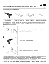
PRODUCT DIMENSIONS
AND CLEARANCES
r
*Height
to
Ceiling
3 1/4"
- .... ..........
20 7/16" _ ......
* The Supplied Duct Cover Fits 8' to 9'-5" Ceiling
Heights. For 9'-6" to 10'-5" ceilings, order zxg00!0.
The vent hood must be installed 24" min., and
30< max. above the cooking surface. The hood
installation height above the cooking surface
depends upon ceiling height.
The telescopic duct cover conceals the ductwork
running from the top of the hood to the ceiling.
The supplied duct cover is sized to reach 8' to 9'-5"
ceiling heights.
The ZX90010 accessorg is available for ceiling
heightsof9'-6"to 10'-5".
INSTALLATION OPTIONS
f ....
24" Plin.
30" Max.
2_____
NOTE: Installation height should be measured from
the cooking surface to the outer glass sides.
This hood may be installed onto a wall and vented
to the outdoors, or it can be installed for recirculatinc
operation. All necessary parts for recirculating
operation are supplied with the hood. No kits
required.
This hood can be installed over any Monogram
electric cooktop or gas cooktop. It cannot be
installed over a Monogram Professional cooktop
or range.

Installation Preparation
ADVANCEPLANNING
• Determinethe exact location of the vent hood.
Planthe route for venting exhaust to the outdoors.
• Usethe shortestand straightest duct route possible.For
satisfactory performance, duct run should not exceed 100 ft.
equivalent length for any duct configurations.
• Referto "Duct Fittings"chart to compute the maximum
permissiblelength for duct runsto the outdoors.
• When applicable, install ang makeup (replacement)
air sgstem in accordance with local building code
requirements. Visit GEAppliances.com for available
makeup air solutions.
ACAUTION: Toreduceriskoffireandtoproperly
exhaust air,be sureto duct air outside-do not vent exhaust
air into spaceswithin walls or ceilingsor into attics,crawl
spacesor garages.
, PRUDENCE :,fautprendresoind'installerun
conduit vers I'ext@ieurpour r@duirelerisque d'incendieet
pouvoir @acuer I'aircorrectement. IIne faut pas@acuer I'air
correctement. IIne faut pas@acuer I'airdans I'espaceentre
lesparois d'un mur,un plafond ou un grenier,un espace
sanitaire ou un garage.
• Usemetal ductwork only.Thesehoods must use
8"round duct.
• Installa wall capwith damper or roof cap at the exterior
opening.Orderthe wall or roof cap and any transition
needed in advance.
Wall Framing for Adequate Support
• Thisvent hood isheavy.Adequate structural support must
be provided in all types of installations.Thehood must
be secured to vertical studs in the wall, or to a horizontal
support.
• Thevent hood should be on site before finalframing and
wall finishing.Thiswill helpto accurately locatethe duct
work and electrical service.
• Installationwill be easierif the vent hood isinstalled before
the cooktop and countertop are installed.
Accessorg Duct Cover
• Thishoodisshipped with a decorative duct coverfor ceiling
heights of 7'-11" to 9'-5".ZX90010duct cover accessory
isavailableto reach 9'-6"to 10'-5" ceilingheights.The
accessoryshould be ordered with the hood and be on site
before installation begins.
POWER SUPPLY
IMPORTANT- (Pleaseread carefullg)
,AWARNING:FORPERSONALSAFE ,THIS
APPLIANCEMUSTBEPROPERLYGROUNDED.
, VERTISSEMENT :POURDES RAISONSDE
SE_CURITE,CETAPPAREILDOITETRECORRECTEMENT MISE
/_LATERRE
Removehousefuse or open circuit breaker before beginning
installation.
Donot usean extensioncord or adapter plug with this
appliance. Follow National electrical codesor prevailing local
codes and ordinances.
Electrical supplg
Thesevent hoods must be suppliedwith 120V,60Hz,and
connected to an individual, properly grounded branch circuit,
and protected by a 15 or 20 amp circuit breaker or time delay
fuse.
• Wiring must be2 wire with ground.
• Ifthe electrical supply does not meet the above
requirements, calla licensedelectrician before proceeding.
° Routehousewiring as closeto the installation location as
possible,in the ceilingor back wall.
° Connectthe hood wiring to the housewiring in accordance
with local codes.
Grounding instructions
Thegrounding conductor must be connected to a grounded
metal, permanent wiring system, or an equipment-grounding
terminal or lead on the hood.
AiJ I^_Lilklr
_I:LVV_III_i II_1_: Theimproper connection of the
equipment-grounding conductor can result in a risk of
electric shock.Checkwith a qualified electricianor service
representative ifyou are in doubt whether the appliance is
properly grounded.
, VERTISSEMENT•
, Lemauvais
branchement du fil de mise @la terre peut causer un choc
@lectrique.Encas de doute, consulter un @lectricienqualifi@ou
un technicien pour d@erminersi I'appareilest 5 la terre.
, CA UTION:Automatically Operated Device-
Toreducethe riskof injury disconnect from power supply
before servicing.Thisunit isequipped with an integral
disconnecting switch located insidethe blower housing.
APRUDENCE :Appareil command@
automatiquement. Afinde r@duirelesrisquesde blessure,
d@branchezI'appareilde I'alimentation @lectriqueavant
de proc6dera une r@aration. L'appareilest @quip@d'un
sectionneur int@ral situ@a I'int@rieurdu Iogementdu
ventilateur.
4

Installation Preparation
DUCT FITTINGS
Use this chart to compute
maximum permissible lengths for
duct runs to outdoors.
NOTE: Do not exceed maximum
permissible equivalent lengths!
Maximum duct length:
100 foot for range hoods.
Flexible ducting:
If flexible metal ducting is used,
all the equivalent feet values in
the table should be doubled.
The flexible metal duct should
be straight and smooth and
extended as much as possible.
DO NOT use flexible plastic
ducting.
NOTE: Ang home ventilation
sbtstem, such as a ventilation
hood, mabt interrupt the proper
flow of combustion air and
exhaust required bbtfireplaces, gas
furnaces, gas water heaters and
other naturallbt vented sbtstems.
To minimize the chance of
interruption of such naturallbt
vented sbtstems, follow the
heating equipment manufacturer's
guidelines and safet_t standards
such as those published bbt NFPA
and ASHRAE. When applicable,
install anbt makeup (replacement)
air sbtstem in accordance with local
building code requirements. Visit
GEAppliances.com for available
makeup air solutions.
Equivalent
Duct Piece Dimensions Length*
Round, 1 ft.
straight (per foot
length)
Total
guantitg Equivalent
Used Length
3-!/4" x !2" ! ft.
straight (per foot
length)
90 ° elbow
!7ft.
!0 ft.
45 ° elbow
3-1/4" x 12"90 ° elbow 43 ft.
3-i/4" x 12"
45 ° elbow 26 ft.
_--_ 3-i/4"x 12"90 ° flat elbow 102 ft.
8" round to" 3-!/4" x !2" transition 2 ft.
_,j_ 3-i/4" x 12" to 8"
round transition 5 ft.
8" round
to 3-i/4" x 12"
transition 90° elbow 6 ft.
3-1/4" x 12" to 8"
round transition 90 ° elbow 13 ft.
Round
wall cap
with damper 32 ft.
3-Z/4" x 12" wall cap
with damper 75 ft.
Round
roof cap 44 ft.
*Actual length of straight duct plus duct fitting
equivalent. Equivalent length of duct pieces are
based on actual tests conducted bLIGE Evaluation
Engineering and reflect requirements for good
venting performance with ang ventilation hood.
Total Duct Run

Installation Preparation
TOOLS AND MATERIALS REQUIRED
(NOT SUPPLIED}
Tape measure
Knife
_, Spirit level
Wire cutter/stripper
_, Wire nuts
Electric drill with 5/16" and 3/8" bits
Phillips and flat blade screwdrivers
Hammer
_, Pliers
Safetg glasses
_, Duct tape
Tape to mount template
Gloves to protect against sharp edges
!20V 60Hz. 15 or 20 Amp, 2 wire with
ground Properlg grounded branch circuit
Strain relief forjunction cover
8" round metal duct, length to suit
installation
Saw,jig saw or reciprocating saw
Measuring tape
Pliers
Duct tape
©
Strain relief
Wire nuts
Spirit level
Electric drill
with 5/16"
and 3/8" Bits
Safetg glasses
Phillips "_
head
screwdriver
Saw, jig saw or
Masking tape reciprocating
saw
%
Gloves
Knife
Wire cutter/
stripper
Hammer
Flat blade
screwdriver
8" round metal
duct, length to suit
installation
REMOVE THE PACKAGING
CAUTION: L,FTTHEHOODOUTOFTHEBOX
BYTHE CENTER METAL PORTION. DO NOT LIFT BY THE
GLASS SIDES.
PRU DENCE : LEVEZLAHO_EA
L'EXTERIEURDE LA BO/TE PAR LA PORTION P1ETAL
CENTRAL. NE LEVEZ PAS PARLES COTES DE VERRE
CAUTION: Wear gloves to protect against
sharp edges.
PRUDENCE : Portez des gants pour 6viter
les blessures caus6es par les tranchants.
. Grasp the hood bg the metal insert in the center
and lift straight up and out of the box.
. Remove and properlg discard the plastic wrapping.
. Remove parts box, duct covers and other
packaging.

Installation Preparation
DETERMINE INSTALLATION HEIGHT
, Telescopic duct covers are provided to conceal
the ductwork running to the ceiling.
, This hood can be installed for recirculating
operation. No kits required.
from the cooking
surface to the
outer glass portion
of the hood.
NOTE: Me
installation height
24" Min.
30" Max.
36" Min.
The vent hood must be installed 24" min. and
30" max. above the cooking surface. The hood
installation height, from the cooking surface to the
bottom of the hood, depends upon ceiling height.
ACCESSORIES:
, Order ZX90010 accessory for ZV900 wall mount
hood to reach ceiling heights between 9'-6" and
10'-5". This accessorg contains one 40" long duct
cover.
Actual
Ceiling
Height
7'-11"
8'-0"
8'-1"
8'-2"
8'-3"
8'-4"
*Possible VENTED
Installation Height
24" to 26"
24" to 27"
24" to 28"
24" to 29"
24" to 30"
24" to 30"
*Possible
RECIRCULATING
Installation Height
24" to 26"
24" to 27"
24" to 28"
24" to 29"
24" to 30"
24" to 30"
8__5 _,
8__6 _,
8'-7"
8'-8"
8'-9"
8'-!0"
24" to 30"
24" to 30"
24" to 30"
24" to 30"
24" to 30"
24" to 30"
24" to 30"
24" to 30"
24" to 30"
24" to 30"
24" to 30"
25" to 30"
8'-11" 24" to 30" 26" to 30"
9'-0" 25" to 30" 24" to 30"
9'-1" 26" to 30" 24" to 30"
9'-2" 27" to 30" 24" to 30"
9'-3" 28" to 30" 24" to 30"
9'-4" 29" to 30" 24" to 30"
9'-5" 30" 25" to 30"
9'-6" 24" to 30"
9'-7" 24" to 30"
9'-8" 24" to 30"
W
.J
t_
w
24" to 30"
24" to 30"
24" to 30" .............
9'-9" 24" to 30" 24" to 30
10'-1" 24" to 30" 24" to 30"
10'-2" 25" to 30" 24" to 30"
10'-3" 26" to 30" 25" to 30"
10'-4" 27" to 30" 26" to 30"
10'-5" 28" to 30" 27" to 30"
*B(]sed on 36S countertop height.

Installation Preparation
CHECK INSTALLATION HARDWARE
Locate the hardware accessorg box packed with the hood and check contents.
m
3
3 wood
screws
2 thumb
screws
HARDWARE PACKAGE
Locate and count
screws
3 wall
fasteners
12 hood
attachment
screws
3 wall bracket
screws
Air deflector for
recirculating
installation onlg
27-3/4"
11_u >'1
Duct bracket
2-piece decorative duct
23-7/8" cover (dimension shown
for reference onlg)
_r, 'HALL
....... t_
Wall mount template
1 charcoal filter for
recirculating installation
Stainless steel filter
0_0 _ "
Mounting bracket

Installation Instructions
INSTALLATION-VENTEDTO THEOUTSIDE
DUCTWORK, WIRING LOCATIONS
Determine the exact location of the vent hood.
, Locate the template packed with the literature.
- Measure 36" from the floor to the top of the cooking
surface. Add hood installation height determined on
page 7. Mark that location.
- Use a level to draw a straight pencil line on the wall.
5-1/2" centerline to wall _-__CEILING VENTDUCTING
A
i Ceiling
8-1/2" dia. hole (" i Centerline 26" above
--_ _ the marked bottom
pencil line for
FOR WALL VENT DUCT_-_ installation height.
,_,_,
REARWALL
_OU_Ne_LATE
m.
,f
- Tape the template in position along the penciled
line. CHECKTO BESURETHE TEMPLATEIS LEVEL.
Ceiling ducting:
If ductwork will vent straight up to the ceiling:
, Use a level to draw a line straight up, from the
centerline on the template to the ceiling.
, Measure 5-1/2" from the back wall to the centerline
of an 8-1/2" hole on the ceiling.
NOTE:If drgwall is not present, add drgwall thickness
to the 5-1/2" dimension.
Wall Ducting:
If ductwork will vent to the rear:
, Use a level to draw a line straight up from the
centerline on the template.
, Measure at least 26" above the pencil line that
indicates the bottom installation height, to the
centerline of an 8-1/2" dia. duct hole. (Hole mag be
elongated for duct elbow.)
HOUSEWIRING LOCATION:
, Thejunction box is located on the top left side of the
hood.
, Wiring should enter the back wall at least 22" above
the bottom of the hood, and within 6" of the left side
of the centerline.
| INSTALL FRAMING FOR HOOD
SUPPORT
IMPORTANT- Framing must be capableof
supporting 100 Ibs.
min. opening for ductwork
View from rear -
1" x 6" min.
mounting
support
Centerline of
installation
space
i
If drgwall is present, mark the screw hole locations for
the top mounting brackets. Remove the template.
, Cut awag enough drgwall to expose 2 vertical studs
at the bracket location indicated on the template.
, Install a horizontal support at least l"x 6" between
two wall studs at the bottom mounting bracket
installation location. The horizontal support must
be flush with the room side of the studs. Use cleats
behind both sides of the support to secure to wall
studs.
, Reinstall drgwall.

Installation instructions
INSTALLATION-VENTEDTO THEOUTSIDE
i2] INSTALL MOUNTING BRACKET
This vent hood must be secured to the horizontal
support or wall studs.
. With the template taped in place, use a punch to
mark mounting bracket screw locations.
. Drill 3/16" pilot holes in 2 of the punched locations
in the lower bracket.
. Remove the template.
t
R_R WALL
r<our_1,r,s_SM_'LA_S
. Use wood screws to secure the mounting bracket
to the wall. The screws must engage wall studs or
the installed horizontal mounting support.
. Check to be sure that the bracket is level.
INSTALL DUCT BRACKET
The duct bracket should be installed against the
back wall and flush with the ceiling. This bracket will
hold the duct cover in place at the top.
Secure the bracket to the wolh
, Align the marked centerline on the bracket with
the centerline on the wall.
, Mark 2 screw hole locations in the wall.
, Drill 3/26" pilot holes in the marked locations.
, If pilot holes do not enter studs, enlarge the holes
to 3/8" and install wall fastener anchors.
, Drive screws, bg hand, into the fasteners to allow
anchors to expand. Remove the screws.
, Secure the bracket to the wall with wood screws
and/or fasteners.
P
/
/
/
/
10

Installation instructions
INSTALLATION-VENTEDTO THEOUTSIDE
PREPARE THE HOOD
, Place the hood on a padded surface.
, Position the motor housing at the back of the hood.
Electrical connectors should face the front, with
rear mounting hooks at the back.
, Slip the bottom flange of the motor housing into
the side slots at the top rear opening.
\
Rear view
Rear
mounting
hooks
, Carefullg lag the hood on its back.
, Fasten the hood to the motor housing from the
bottom, using 6 screws.
Front side
\ /
)}
, Join two cable connectors at the front of the hood.
Engage flange on
motor housing into slots
Control
Panel
11

Installation Instructions
INSTALLATION-VENTEDTO THEOUTSIDE
_-_ MOUNT THE HOOD
WARNING: 2peopleare required to lift and
position the hood onto the mounting bracket.
AVERTISSEIENT :
If faut deux personnes pour lever et mettre en place
la hotte sur le support de montage.
, Lift the hood onto the mounting bracket.
, Position a spirit level at the bottom of the hood to
check side to side leveling.
[6] LEVEL THE HOOD
This hood has built-in levelers on the mounting hooks
at each side. Use a long Phillips screwdriver from the
front to access the levelers.
, Use the top screw hole in the leveler to raise or lower
the hood on that side.
, Use the bottom screw hole to pull the hood tight
against the wall surface.
Screw hole
, Mark hole location at the bottom of the hood.
, Remove the hood. If the bottom screw hole does not
enter a stud, enlarge the hole to 3/8% and install wall
fastener anchors.
, Place the hood back onto the mounting bracket,
check level again and install the wall fastener.
[-_ CONNECT DUCTWORK
, Install ductwork, making connections in the
direction of airflow as illustrated.
, Push duct over the exhaust outlet and damper.
, Secure joints in ductwork with sheetmetal screws.
, Wrap oil duct joints and the flange connections
with duct tope for on airtight seal.
Airflow
Duct tape -_t--
over seam
and screw
-- Screw
CAUTION: Do not use sheet metal screws
at the hood flange connection. Doing so will prevent
proper damper operation. Seal connection with
tope onlg.
PRUDENCE:
II ne fout pos utiliser de vis autorourdeuses (_Io
connexion du collet de la hotte. Ceci emp6cheroit
le ban fonctionnement du registre. N'utiliser que du
ruban adh6sif pour assurer 1'6tanch6it6 du raccord.
12

Installation Instructions
INSTALLATION-VENTEDTO THEOUTSIDE
[_ CONNECT ELECTRICAL
Verify that power is turned off at the source.
WARNING: ,f house wiring is not 2-wire
with a ground wire, a ground must be provided by
the installer. When house wiring is aluminum, be sure
to use U.L approved anti-oxidant compound and
aluminum-to-copper connectors.
AVERTISSEMENT :
Sila maison n'est pas cablee avec deux ills et un
fil de terre, I'installateur dolt installer un fil de terre.
Ouand les ills sont en aluminium, il faut prendre soin
d'utiliser des connecteurs aluminium a cuivre avec
une pate antioxgdante approuv6e par U.L.
, Removejunction box cover and knockout on the
left side.
Knockout
, Secure the house wiring to the junction box with
a strain relief.
House wiring\
J-Box
cover.
, Connect white leads to branch circuit white lead.
, Connect black leads to branch circuit black lead.
, Connect green/gellow leads to branch circuit green
lead or bare ground lead.
, Secure all connections with wire nuts on each
electrical connector.
, Push wires into junction box and replace cover.
Besure wires are not pinched.
, Secure J-Box cover with original screw.
13

Installation instructions
INSTALLATION-VENTEDTO THEOUTSIDE
i-9-1INSTALL DUCT COVERS
. Place the decorative duct .__
covers on top of the hood. Plounting_
NOTE:The inside (upper) screws I J
duct piece has holes on one J:_,_ j
end. The holes are intended
for use when the hood is
installed for recirculating
purposes. Slide the inside end
into the outer piece; the vent !._ j
holes should not be visible in
this installation.
The inside duct piece must slip into the folded ends
of the outer section.
Upper
duct cover
Duct cover
support bracket
Duct cover
support bracket
Lower
duct cove_. _,.
Lower duct %-_'_ .A
cover seat
, Extend the inner duct upward to the ceiling
bracket.
. Secure duct cover to ceiling bracket with 2 screws.
INSTALL FILTERS
IMPORTANT: Check to be sure that the main ON/
OFF switch next to the motor is in the ON position.
, Remove protective film on the filters.
Filter Lock
NOTE: The charcoal filter is not required for this
installation.
, Tip the filter into the left or right side of the
opening. Lift the filter to the opposite side and
into the filter lock.
. To remove the filter, pull the filter lock downward.
[-_ FINALIZE INSTALLATION
, Check to be sure all tape and packaging materials
have been removed.
, Refer to the Owner's Manual for operating
instructions.
14

Installation Instructions
INSTALLATI ON--R ECIRCULATI NG
DUCTWORK, WIRING LOCATIONS
, Determine the exact location of the vent hood.
, Locate the template packed with the literature.
, Measure 36_<from the floor to the top of the cooking
surface. Add hood installation height determined on
page 7. Mark that location.
Ceiling
_EARWALL
MOU_NGTEMP_ATE
,!
, Tape the template in position along the penciled line.
CHECKTO BESURETHE TEMPLATEISLEVEL.
, Use a level to draw a line straight up, from the
centerline on the template to the ceiling.
HOUSEWIRING LOCATION:
, Thejunction box is located on the top left side of
the hood.
, Wiring should enter the back wall at least 22_<
above the bottom of the hood, and within 6_<
of the centerline.
INSTALL FRAMING FOR HOOD
SUPPORT
IMPORTANT: Fromingmustbecapable of
supporting 100 Ibs.
I
Centerline of
installation
space
View from rear
cleats
1" x 6" min.
mounting
support
If drgwall is present, mark the screw hole locations for
the top mounting brackets. Remove the template.
, Cut awag enough drgwall to expose 2 vertical studs
at the bracket location indicated on the template.
, Install a horizontal support at least 1" x 6"
between two wall studs at the bottom mounting
bracket installation location. The horizontal support
must be flush with the room side of the studs.
Use cleats behind both sides of the support to
secure to wall studs.
, Reinstall drgwall.
15

Installation Instructions
INSTALLATI ON--R ECIRCULATI NG
INSTALL MOUNTING BRACKET
This vent hood must be secured to the horizontal
support or wall studs.
, With the template taped in place, use a punch to
mark mounting bracket screw locations.
, Drill ]/16" pilot holes in 2 of the punched locations
in the lower bracket.
, Remove the template.
R_f, WALL
, Use wood screws to secure the mounting bracket
to the wall. The screws must engage wall studs or
the installed horizontal mounting support.
, Check to be sure that the bracket is level.
[-_ INSTALL DUCT BRACKET
The duct bracket should be installed against the
back wall and flush with the ceiling. This bracket will
hold the duct cover in place at the top.
Secure the bracket to the wall:
, Align the marked centerline on the bracket with
the centerline on the wall.
, Mark 2 screw hole locations in the wall.
, Drill 3/164 pilot holes in the marked locations.
, If pilot holes do not enter studs, enlarge the holes
to ]/84 and install wall fastener anchors.
, Drive screws, bg hand, into the fasteners to allow
anchors to expand. Remove the screws.
, Secure the bracket to the wall with wood screws
and/or fasteners.
/
/
/,
16

Installation Instructions
INSTALLATI ON--R ECIRCULATI NG
PREPARE THE HOOD
, Place the hood on a padded surface.
, Position the motor housing at the back of the hood.
Electrical connectors should face the front, with
rear mounting hooks at the back.
, Slip the bottom flange of the motor housing into
the side slots at the top rear opening.
\
Rear view
mounting
hooks
Engage flange on
motor housing into slots
, Carefully lay the hood on its back.
, Fasten the hood to the motor housing from the
bottom, using 6 screws.
Front side
, Join two cable connectors at the front of the hood.
To Lights
To
Control
Panel
MOUNT THE HOOD
WARNING: 2 people are required to lift and
position the hood onto the mounting bracket.
AVERTISSEMENT :
If faut deux personnes pour lever et mettre en place
la hotte sur le support de montage.
, Lift the hood onto the mounting bracket.
, Position a spirit level at the bottom of the hood to
check side to side leveling.
LEVEL THE HOOD
This hood has built-in levelers on the mounting hooks
at each side. Use a long Phillips screwdriver from the
front to access the levelers.
® @
, Use the top screw hole in the leveler to raise or lower
the hood on that side.
, Use the bottom screw hole to pull the hood tight
against the wall surface.
17
Screw hole
, Hark hole location atthe bottom of the hood.
, Remove the hood. If the bottom screw hole does not
enter a stud, enlarge the hole to 3/84 and install wall
fastener anchors.
, Place the hood back onto the mounting bracket,
check level again and install the wall fastener.

Installation Instructions
INSTALLATI ON--R ECIRCULATI NG
| SIZE AND CUT DUCT PIECE
, Hold upper air deflector
with duct connector
against the ceiling.
, Measure from the bottom
of the air deflector to the
top of the hood as
Measure
shown. Reduce length
that dimension bg
1" to facilitate installation.
The duct will cover
and overlap the deflector
and the hood outlets.
P
Deflector
%
i;
, Cut the duct piece to size and
slip onto the bottom of the
deflector.
, Place the assembled deflector
and duct over the exhaust
outlet.
. Hold the assemblg against the
duct bracket.
. Drive a screws into the bottom
of the deflector and into the
bracket.
. Use duct tape to seal duct
to the deflector and at the
exhaust outlet.
18
_-1 CONNECT ELECTRICAL
Verify that power is turned off at the source.
WARNING: _fhouse wiring is not 2-wire
with a ground wire, a ground must be provided bg
the installer. When house wiring is aluminum, be
sure to use U.L approved anti-oxidant compound
and aluminum-to-copper connectors.
AVERTISSEMENT :
Si la maison n'est pas c@blee avec deux ills et un
fil de terre, I'installateur dolt installer un fil de terre.
Ouand les ills sont en aluminium, il faut prendre soin
d'utiliser des connecteurs aluminium a cuivre avec
une pate antioxgdante approuv@ par U.L
, Remove junction box cover and knockout on the
left side.
Knockout
J-Box
cover.\
. Secure the house wiring to the junction box with
a strain relief.
House wiring...
J-Box
cover_
, Connect white leads to branch circuit white lead.
, Connect black leads to branch circuit black lead.
, Connect green/gellow leads to branch circuit
green lead or bare ground lead.
, Secure all connections with wire nuts on each
electrical connector.
, Push wires into junction box and replace cover.
Be sure wires are not pinched.
, Secure J-Box cover with original screw.

Installation Instructions
INSTALLATI ON--R ECIRCULATI NG
[-_ INSTALL DUCT COVERS
, Place the decorative duct
covers on top of the hood.
NOTE: The inside piece has
holes on one end intended for
use when the hood is installed
for recirculating purposes.
Be sure the vented end is at
the top; the vent holes will
be visible in this installation.
The inside duct piece must slip
into the folded ends on the outer
section.
Haunting
screw holes
Vent holes
Upper
duct cover
Lower
duct cover
Duct cover
support bracket
Duct cover
support bracket
Lower duct
cover seat
, Extend the inner duct upward to the ceiling
bracket.
, Secure duct cover to ceiling bracket with 2 screws.
INSTALL FILTERS
IMPORTANT: Check to be sure that the main ON/
OFF switch next to the motor is in the ON position.
Charcoal filter
i
i
, Install the black charcoal filter into the center
opening. Secure the filter with thumbscrews on
each side.
Metal filter
Filter Lock
, Tip the filter into the left or right side of the
opening. Lift the filter to the opposite side and into
the filter lock.
, To remove the filter, pull the filter lock downward.
i-_ FINALIZE INSTALLATION
, Remove all tape and packing material.
, Refer to the Owner's Manual for operating
instructions.
19

[49-80328-3 1
02-13 GE
Printed in Mexico
NOTE: While performing installations described inthis book,
safetg glasses or goggles should be worn.
For Monogram _ local service in your area, call
1.800.44¢.18¢5.
NOTE: Product improvement is a continuing endeavor at
General Electric. Therefore, materials, appearance and
specifications are subject to change without notice.
Monogram:
GE Appliances & Lighting
Appliances
General Electric Company
Louisville, KY 40225
monogram.corn
/