Page is loading ...

KNOOK UNDERCABINET
JBKNOOK
INSTALLATION INSTRUCTIONS
Thank you for buying RAB lighting xtures. Our goal is to design the best quality products to get the job done right. We’d like to hear your comments.
Call the Marketing Department at 888-RAB-1000 or email: marketing@rabweb.com
TM
SAFETY INSTRUCTIONS
WARNING: Make certain power is OFF before installing or maintaining xture. No user serviceable parts inside.
WARNING: Risk of re or electric shock. SUITABLE FOR INDOOR DRY LOCATIONS ONLY.
WARNING: To prevent overheating do not install in small enclosed spaces.
WARNING: Do not install this product in an environment outside the listed ambient temperature (-20°C to +40°C).
WARNING: 300W maximum linear run, do not use this Junction Box to provide power to other products.
IMPORTANT
READ CAREFULLY BEFORE INSTALLING FIXTURE. RETAIN THESE INSTRUCTIONS FOR FUTURE REFERENCE.
Fixtures must be wired in accordance with the National Electrical Code and all applicable local codes. Proper grounding is required
for safety. THIS PRODUCT MUST BE INSTALLED IN ACCORDANCE WITH THE APPLICABLE INSTALLATION CODE BY A PERSON
FAMILIAR WITH THE CONSTRUCTION AND OPERATION OF THE PRODUCT AND THE HAZARDS INVOLVED.
Knockout
Electrical Port
Junction Box
Cover Screws and
Lockwashers(2 ea.)
JBKNOOK
Alternate
Knockouts
3/8” Wire Connector
(supplied)
Junction Box
Fixture
Jumper Cable
(Ordered seperately)
On-O Switch
Junction Box
Cover
Clamping
Screws (2)
Lock Nut
Captive Screws (2)
MOUNTING INSTRUCTIONS
The xture is suitable for indoor dry locations only.
1. Remove Junction Box Cover Screws (2) and remove Cover.
Save Screws and Lockwashers.
2. Prepare electrical wire(s) (supplied by others) by stripping
conductor ends approximately 3/8”.
3. For installation using 3/8” Wire Connector (supplied)
determine mounting orientation and remove one KNOCKOUT
on desired side of Junction Box for electrical supply and
attach 3/8” Wire Connector to Junction Box as shown. Outer
wire jacket must protude through 3/8” Wire Connector to
adequately protect internal conductors.
4. Secure 3/8” Wire Connector to Junction Box by tightening
the Locknut then tightening Clamping Crews(2) on electrical
connector tting securely.
5. Push stripped wire(s) ends into PUSH-IN WIRE CONNECTORS
(see WIRING DIAGRAM). Push excess electrical supply wire(s)
back into wall.
6. Secure Junction Box to mounting surface using (2) Captive
Screws (supplied), be careful not to drive screws all the way
through the cabinet bottom. Use shorter screws if neccessary
(supplied by others).
7. Replace and secure Junction Box Cover with supplied screws.
Make certain Lockwashers are located beneath screw heads
to properly ground cover.
8. Follow installation instructions provided with undercabinet
light xture for mounting and connector options.
9. Before powering on make sure that all xtures connected to
Junction Box have been properly installed and that all open
Electrical Ports on the Junction Box and xtures are safely
covered with Electrical Port Covers.

KNOOK UNDERCABINET
JBKNOOK
INSTALLATION INSTRUCTIONS
Thank you for buying RAB lighting xtures. Our goal is to design the best quality products to get the job done right. We’d like to hear your comments.
Call the Marketing Department at 888-RAB-1000 or email: marketing@rabweb.com
TM
TROUBLESHOOTING
1. Check that the line voltage at xture is correct. Refer to
wiring directions.
2. Is the xture grounded properly?
CLEANING & MAINTENANCE
CAUTION: Be sure xture temperature is cool enough
to touch. Do not clean or maintain while xture is
energized.
1. Clean polycarbonate lens with non-abrasive glass
cleaning solution.
2. Do not open xture to clean the LED. Do not touch the
LED.
JBKNOOK IN-0816
Easy Installation & Product Help
Tech Help Line
Call our experts 888 RAB-1000
©2016 RAB LIGHTING Inc.
Northvale, New Jersey 07647 USA
rabweb.com
Visit our website for product info
email
Answered promptly sales@rabweb.com
Note: These instructions do not cover all details or variations in equipment nor do they provide for every possible situation during installation operation or
maintenance.
ONOFF WIRING
Make sure the supply voltage is the same as the luminaire
voltage, see xture spec label.
1. Connect the black xture lead to the LINE supply lead.
2. Connect the white xture lead to the COMMON supply lead.
3. Connect the GROUND wire from xture to supply ground.
LIGHT
FIXTURE
(+)LINE BLACK
(-)COMMON WHITE
GROUND GROUND

Thank you for buying RAB lighting xtures. Our goal is to design the best quality products to get the job done right. We’d like to hear your comments.
Call the Marketing Department at 888-RAB-1000 or email: marketing@rabweb.com
KNOOK UNDERCABINET
INSTALLATION INSTRUCTIONS
TM
SAFETY INSTRUCTIONS
WARNING: Risk of re or electric shock. SUITABLE FOR INDOOR DRY LOCATIONS ONLY.
WARNING: To prevent overheating do not install in small enclosed spaces.
WARNING: Do not install this product in an environment outside the listed ambient
temperature (-20° to +40°C).
WARNING: 300W maximum linear run.
IMPORTANT
READ CAREFULLY BEFORE INSTALLING FIXTURE. RETAIN THESE INSTRUCTIONS FOR FUTURE REFERENCE.
Fixtures must be wired in accordance with the National Electrical Code and all applicable local codes. Proper grounding is required
for safety. THIS PRODUCT MUST BE INSTALLED IN ACCORDANCE WITH THE APPLICABLE INSTALLATION CODE BY A PERSON
FAMILIAR WITH THE CONSTRUCTION AND OPERATION OF THE PRODUCT AND THE HAZARDS INVOLVED.
WARNING: Make certain power is OFF before installing or maintaining xture. No user serviceable parts inside.
Knockout
Housing
Rear Access
Door Screw
MOUNTING INSTRUCTIONS
The xture is suitable for indoor dry locations only.
1. Determine location to install xture(s).
WARNING: To prevent wiring damage or abrasion, do
not expose wiring to edges of sharp objects.
2. Access wiring compartments using option A or B:
A) Rear access door knockout (Fig. 1).
Remove Knockout by using a punch tool (not
supplied). Loosen Rear Access Door Screw and
remove door.
B) Alternate Knockouts for 24” or 32” only(Fig. 2 and 3).
Alternate Knockouts are located along back and top
of housing. Remove Wiring Compartment Cover.
3. To access internal wiring remove Wiring Compartment
Cover (Fig.3).Feed wires through 3/8” Wire Connector
(supplied) and install connector to Rear Access Door.
Wire cable to push in connectors. Secure Rear Access
Door to xture (Fig. 4).
4. Secure xture to mounting surface using (2) at head
wood screws (supplied), be careful not to drive screws all
the way through the cabinet bottom. Use shorter screws
if neccessary (supplied by others). Once the xture is
secure to surface insert Screw Hole Covers (supplied).
KNOOK 8”
KNOOK 16”
KNOOK 24”
KNOOK 32”
Fig. 1
Alternate Knockouts
24”, 32” only
Fig. 2
Wiring Compartment Cover
On-O
Switch
Screw Hole Covers
(supplied)
Rear Access Door
3/8” Wire Connector
(supplied)
Push-In Connectors
Fig. 3
Fig. 4

Thank you for buying RAB lighting xtures. Our goal is to design the best quality products to get the job done right. We’d like to hear your comments.
Call the Marketing Department at 888-RAB-1000 or email: marketing@rabweb.com
KNOOK UNDERCABINET
INSTALLATION INSTRUCTIONS
TM
INTERCONNECTING FIXTURES
Use In-Line Connector supplied with each xture to connect
xtures directly to each other end-to end.
ACCESSORIES OCSKNOOK
ordered separately)
Use Junction Box with Motion Sensor (ordered separately) for
automatic on/o control.
ACCESSORIES JBKNOOK
ordered separately)
Use Junction Box (ordered separately) to split electrical
connections between two xtures.
In-Line Connector (supplied)
ACCESSORIES KJC6, KJC12
KJC24, KJC72 ordered separately)
Use 6”, 12”, 24”, 72” exible Jumper Cables (ordered separately)
ACCESSORIES KPCJ
ordered separately)
Use 6FT exible Cord and Plug (ordered separately) to
power xture.
ACCESSORIES KPCJ
ordered separately)
Use 6FT exible Power Feed Cord (ordered separately) to
connect xture to Junction Box (supplied by others).
Junction box with Occupancy Sensor
(ordered separately)
Junction Box
(ordered separately)
Jumper Cable
(ordered separately)
Cord and Plug
(ordered separately)
Power Feed Cord
(ordered separately)
Fixture
Fixture

Thank you for buying RAB lighting xtures. Our goal is to design the best quality products to get the job done right. We’d like to hear your comments.
Call the Marketing Department at 888-RAB-1000 or email: marketing@rabweb.com
KNOOK UNDERCABINET
INSTALLATION INSTRUCTIONS
TM
YELLOW/GREEN
GROUND
( - ) COMMON
( + ) LINE
BLACK
WHITE
LIGHT
FIXTURE
• DIVA DV-603P
• SKYLARK S-600P
• SKYLARK SELV-300P
• SKYLARK CTCL-153P
• DECORA IPL06-10Z
• DECORA 6631-P
• COOPER-TAL06P-C1
• LUTRON-RRD-8ANS-WH
• LUTRON-RRD-6NA-WH
• LEVITON 35A00-1
TROUBLESHOOTING
1. Check that the line voltage at xture is correct. Refer to
wiring directions.
2. Is the xture grounded properly?
CLEANING & MAINTENANCE
CAUTION: Be sure xture temperature is cool enough
to touch. Do not clean or maintain while xture is
energized.
1. Clean polycarbonate lens with non-abrasive glass
cleaning solution.
2. Do not open xture to clean the LED. Do not touch the
LED.
KNOOK IN-0816
Easy Installation & Product Help
Tech Help Line
Call our experts 888 RAB-1000
©2016 RAB LIGHTING Inc.
Northvale, New Jersey 07647 USA
rabweb.com
Visit our website for product info
email
Answered promptly sales@rabweb.com
Note: These instructions do not cover all details or variations in equipment nor do they provide for every possible situation during installation operation or
maintenance.
ONOFF WIRING
Make sure the supply voltage is the same as the luminaire
voltage, see xture spec label. Diming compatible with most
incandescent dimmers.
1. Connect the black xture lead to the LINE supply lead.
2. Connect the white xture lead to the COMMON supply lead.
3. Connect the GROUND wire from xture to supply ground.
COMPATIBLE DIMMERS
This partial list contains a representative selection of known
compatible dimming controls.

KNOOK UNDERCABINET
OCSKNOOK INSTALLATION INSTRUCTIONS
Thank you for buying RAB lighting xtures. Our goal is to design the best quality products to get the job done right. We’d like to hear your comments.
Call the Marketing Department at 888-RAB-1000 or email: marketing@rabweb.com
TM
SAFETY INSTRUCTIONS
WARNING: Make certain power is OFF before installing or maintaining xture. No user serviceable parts inside.
WARNING: Risk of re or electric shock. SUITABLE FOR INDOOR DRY LOCATIONS ONLY.
WARNING: To prevent overheating do not install in small enclosed spaces.
WARNING: Do not install this product in an environment outside the listed ambient temperature( -20°C to +40°C).
WARNING: 300W maximum linear run, do not use this Junction Box to provide power to other products.
IMPORTANT
READ CAREFULLY BEFORE INSTALLING FIXTURE. RETAIN THESE INSTRUCTIONS FOR FUTURE REFERENCE.
Fixtures must be wired in accordance with the National Electrical Code and all applicable local codes. Proper grounding is required
for safety. THIS PRODUCT MUST BE INSTALLED IN ACCORDANCE WITH THE APPLICABLE INSTALLATION CODE BY A PERSON
FAMILIAR WITH THE CONSTRUCTION AND OPERATION OF THE PRODUCT AND THE HAZARDS INVOLVED.
OCSKNOOK
OCCUPANCY SENSOR
SPECIFICATIONS
Input Voltage: 120V
Operational Frequency: 50/60Hz
Time Delay: 30 seconds, 10 min, 20 min, 30 min
Operating Temperature: 0°C to 55°C (32°F to 131°F)
Mounting Height: reduced sensitivity, 8ft
optimal sensitivity, 6ft
Coverage Diameter: 10ft at 8ft mounting height
OPERATION
• Uses passive infrared technology to detect motion
• Heat from occupants of room triggers sensor into Auto-on
• Lack of detection triggers Time Delay
• If Time Delay period elapses with no detected motion,
xture will turn o
• Motion detection during Time Delay period stops Time
Delay and xture remains on
• Movement must occur across zones of detection (see
coverage diagram below
COVERAGE DIAGRAM
10' 10'8'
8'
6'
4'
2'
0'
2'
4'
6'
8'
6' 4' 2' 0' 2' 4' 6' 8'
10'
SETTING TIME DELAY
• Turn dial to desired
Time Delay period
• Dial is located on
sensor surface
10 M 20 M
30 M
30 S
TIME DELAY

KNOOK UNDERCABINET
OCSKNOOK INSTALLATION INSTRUCTIONS
Thank you for buying RAB lighting xtures. Our goal is to design the best quality products to get the job done right. We’d like to hear your comments.
Call the Marketing Department at 888-RAB-1000 or email: marketing@rabweb.com
TM
TROUBLESHOOTING
1. Check that the line voltage at xture is correct. Refer to
wiring directions.
2. Is the xture grounded properly?
CLEANING & MAINTENANCE
CAUTION: Be sure xture temperature is cool enough
to touch. Do not clean or maintain while xture is
energized.
1. Clean polycarbonate lens with non-abrasive glass
cleaning solution.
2. Do not open xture to clean the LED. Do not touch the
LED.
OCSKNOOK IN-0916
Easy Installation & Product Help
Tech Help Line
Call our experts 888 RAB-1000
©2016 RAB LIGHTING Inc.
Northvale, New Jersey 07647 USA
rabweb.com
Visit our website for product info
email
Answered promptly sales@rabweb.com
Note: These instructions do not cover all details or variations in equipment nor do they provide for every possible situation during installation operation or
maintenance.
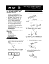
MOUNTING INSTRUCTIONS
The xture is suitable for indoor dry locations only.
1. Remove Junction Box Cover Screws (2) and remove Cover.
Save Screws and Lockwashers.
2. Prepare electrical wire(s) (supplied by others) by stripping
conductor ends approximately 3/8”.
3. For installation using 3/8” Wire Connector (supplied)
determine mounting orientation and remove one KNOCKOUT
on desired side of Junction Box for electrical supply and
attach 3/8” Wire Connector to Junction Box as shown. Outer
wire jacket must protude through 3/8” Wire Connector to
adequately protect internal conductors.
4. Secure 3/8” Wire Connector to Junction Box by tightening
the Locknut then tightening Clamping Crews(2) on electrical
connector tting securely.
5. Push stripped wire(s) ends into PUSH-IN WIRE CONNECTORS
(see WIRING DIAGRAM). Push excess electrical supply wire(s)
back into wall.
6. Secure Junction Box to mounting surface using (2) Captive
Screws (supplied), be careful not to drive screws all the way
through the cabinet bottom. Use shorter screws if neccessary
(supplied by others).
7. Replace and secure Junction Box Cover with supplied screws.
Make certain Lockwashers are located beneath screw heads
to properly ground cover.
8. Follow installation instructions provided with undercabinet
light xture for mounting and connector options.
9. Before powering on make sure that all xtures connected to
Junction Box have been properly installed and that all open
Electrical Ports on the Junction Box and xtures are safely
covered with Electrical Port Covers.
Knockout
Electrical Port
Junction Box
Cover Screws and
Lockwashers(2 ea.)
Alternate
Knockouts
Occupancy Sensor
3/8” Wire Connector
(supplied)
OCS Junction Box
Fixture
Jumper Cable
(ordered separately)
On-O Switch
Junction Box
Cover
Clamping
Screws (2)
Lock Nut
Captive Screws (2)

KNOOK UNDERCABINET
OCSKNOOK INSTALLATION INSTRUCTIONS
Thank you for buying RAB lighting xtures. Our goal is to design the best quality products to get the job done right. We’d like to hear your comments.
Call the Marketing Department at 888-RAB-1000 or email: marketing@rabweb.com
TM
SAFETY INSTRUCTIONS
WARNING: Make certain power is OFF before installing or maintaining xture. No user serviceable parts inside.
WARNING: Risk of re or electric shock. SUITABLE FOR INDOOR DRY LOCATIONS ONLY.
WARNING: To prevent overheating do not install in small enclosed spaces.
WARNING: Do not install this product in an environment outside the listed ambient temperature( -20°C to +40°C).
WARNING: 300W maximum linear run, do not use this Junction Box to provide power to other products.
IMPORTANT
READ CAREFULLY BEFORE INSTALLING FIXTURE. RETAIN THESE INSTRUCTIONS FOR FUTURE REFERENCE.
Fixtures must be wired in accordance with the National Electrical Code and all applicable local codes. Proper grounding is required
for safety. THIS PRODUCT MUST BE INSTALLED IN ACCORDANCE WITH THE APPLICABLE INSTALLATION CODE BY A PERSON
FAMILIAR WITH THE CONSTRUCTION AND OPERATION OF THE PRODUCT AND THE HAZARDS INVOLVED.
OCSKNOOK
OCCUPANCY SENSOR
SPECIFICATIONS
Input Voltage: 120V
Operational Frequency: 50/60Hz
Time Delay: 30 seconds, 10 min, 20 min, 30 min
Operating Temperature: 0°C to 55°C (32°F to 131°F)
Mounting Height: reduced sensitivity, 8ft
optimal sensitivity, 6ft
Coverage Diameter: 10ft at 8ft mounting height (Fig. 1)
OPERATION
• Uses passive infrared technology to detect motion
• Heat from occupants of room triggers sensor into Auto-on
• Lack of detection triggers Time Delay
• If Time Delay period elapses with no detected motion,
xture will turn o
• Motion detection during Time Delay period stops
Time Delay and xture remains on
• Movement must occur across zones of detection (see
Coverage Diagram (Fig. 1)
COVERAGE DIAGRAM
10' 10'8'
8'
6'
4'
2'
0'
2'
4'
6'
8'
6' 4' 2' 0' 2' 4' 6' 8'
10'
SETTING TIME DELAY
• Turn dial to desired
Time Delay period
(see Fig. 2)
• Time Delay Setting Dial
• is located on
• sensor surface
(see Fig. 3)
10 M
20 M
30 M
30 S
TIME DELAY
Fig.1
Fig. 2

KNOOK UNDERCABINET
OCSKNOOK INSTALLATION INSTRUCTIONS
Thank you for buying RAB lighting xtures. Our goal is to design the best quality products to get the job done right. We’d like to hear your comments.
Call the Marketing Department at 888-RAB-1000 or email: marketing@rabweb.com
TM
TROUBLESHOOTING
1. Check that the line voltage at xture is correct. Refer to
wiring directions.
2. Is the xture grounded properly?
CLEANING & MAINTENANCE
CAUTION: Be sure xture temperature is cool enough
to touch. Do not clean or maintain while xture is
energized.
1. Clean polycarbonate lens with non-abrasive glass
cleaning solution.
2. Do not open xture to clean the LED. Do not touch the
LED.
OCSKNOOK IN-1216
Easy Installation & Product Help
Tech Help Line
Call our experts 888 RAB-1000
©2016 RAB LIGHTING Inc.
Northvale, New Jersey 07647 USA
rabweb.com
Visit our website for product info
email
Answered promptly sales@rabweb.com
Note: These instructions do not cover all details or variations in equipment nor do they provide for every possible situation during installation operation or
maintenance.
MOUNTING INSTRUCTIONS
The xture is suitable for indoor dry locations only.
1. Remove Junction Box Cover Screws (2) and remove Cover.
Save Screws and Lockwashers (see Fig. 4)
2. Prepare electrical wire(s) (supplied by others) by stripping
conductor ends approximately 3/8”.
3. For installation using 3/8” Wire Connector (supplied)
determine mounting orientation and remove one KNOCKOUT
on desired side of Junction Box for electrical supply and
attach 3/8” Wire Connector to Junction Box as shown. Outer
wire jacket must protude through 3/8” Wire Connector to
adequately protect internal conductors.
4. Secure 3/8” Wire Connector to Junction Box by tightening
the Locknut then tightening Clamping Crews(2) on electrical
connector tting securely.
5. Push stripped wire(s) ends into PUSH-IN WIRE CONNECTORS
(see WIRING DIAGRAM). Push excess electrical supply wire(s)
back into wall.
6. Secure Junction Box to mounting surface using (2) Captive
Screws (supplied), be careful not to drive screws all the way
through the cabinet bottom. Use shorter screws if neccessary
(supplied by others).
7. Replace and secure Junction Box Cover with supplied screws.
Make certain Lockwashers are located beneath screw heads
to properly ground cover.
8. Follow installation instructions provided with undercabinet
light xture for mounting and connector options (Fig. 5).
9. Before powering on make sure that all xtures connected to
Junction Box have been properly installed and that all open
Electrical Ports on the Junction Box and xtures are safely
covered with Electrical Port Covers.
Knockout
Electrical Port
Junction Box
Cover Screws and
Lockwashers(2 ea.)
Alternate
Knockouts
Occupancy Sensor
3/8” Wire Connector
(supplied)
OCS Junction Box
Fixture
Jumper Cable
(ordered separately)
On-O Switch
Junction Box
Cover
Clamping
Screws (2)
Lock Nut
Captive Screws (2)
Occupancy Sensor
Time Delay Setting Dial
Junction Box
Junction Box Cover
Fig. 3
Fig. 4
Fig. 5
/