Page is loading ...

Instruction Manual
thermoMETER CSL
CSL-SF
CSLM-2

MICRO-EPSILON
MESSTECHNIK
GmbH & Co. KG
Königbacher Strasse 15
94496 Ortenburg / Germany
Tel. +49 (0) 8542 / 168-0
Fax +49 (0) 8542 / 168-90
www.micro-epsilon.com
Certified acc. to DIN EN ISO 9001: 2008
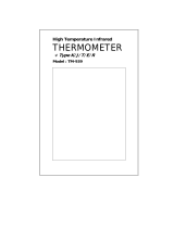
Infrared sensor

thermoMETER CSL
Contents
1. Safety ........................................................................................................................................ 5
1.1 Symbols Used ................................................................................................................................................. 5
1.2 Warnings .......................................................................................................................................................... 5
1.3 Notes on CE Identification ............................................................................................................................... 6
1.4 Proper Use ....................................................................................................................................................... 6
1.5 Proper Environment ......................................................................................................................................... 7
2. Technical Data .......................................................................................................................... 8
2.1 Functional Principle ......................................................................................................................................... 8
2.2 Sensor Models ................................................................................................................................................. 9
2.3 General Specifications ..................................................................................................................................... 9
2.4 Electrical Specifications ................................................................................................................................. 10
2.5 Measurement Specifications ........................................................................................................................ 11
3. Delivery ................................................................................................................................... 12
3.1 Unpacking ...................................................................................................................................................... 12
3.2 Storage .......................................................................................................................................................... 12
4. Optical Charts ......................................................................................................................... 13
5. Mechanical Installation .......................................................................................................... 18
6. Electrical Installation .............................................................................................................. 19
6.1 Cable Connections ........................................................................................................................................ 19
6.1.1 Basic Version ................................................................................................................................ 19
6.1.2 Power Supply ............................................................................................................................... 19
6.1.3 Pin Assignment (Sensor Terminal Block) ..................................................................................... 20
6.2 Analog Mode ................................................................................................................................................. 20
6.3 Digital Mode ................................................................................................................................................... 21
6.4 Digital and Analog Mode Combined ............................................................................................................. 22
6.5 Maximum Loop Impedance ........................................................................................................................... 22
7. Emissivity Setting ................................................................................................................... 23
8. Laser Sighting ........................................................................................................................ 24

thermoMETER CSL
9. Instructions for Operation...................................................................................................... 25
9.1 Cleaning ......................................................................................................................................................... 25
10. CompactConnect Software .................................................................................................... 26
10.1 Installation ...................................................................................................................................................... 26
10.2 System Requirements ................................................................................................................................... 26
10.3 Main Features ................................................................................................................................................ 27
10.4 Communication Settings ............................................................................................................................... 27
10.4.1 Serial Interface .............................................................................................................................. 27
10.4.2 Protocol ........................................................................................................................................ 27
10.5 Digital Command Set .................................................................................................................................... 28
11. Basics of Infrared Thermometry ............................................................................................ 30
12. Emissivity ................................................................................................................................ 31
12.1 Definition ........................................................................................................................................................ 31
12.2 Determination of Unknown Emissivity ........................................................................................................... 31
12.3 Characteristic Emissivity ................................................................................................................................ 32
13. Warranty .................................................................................................................................. 33
14. Service, Repair ....................................................................................................................... 34
15. Decommissioning, Disposal .................................................................................................. 34
Appendix
A 1 Accessories ............................................................................................................................ 35
A 1.1 Mounting Brackets ......................................................................................................................................... 35
A 1.2 Air Purge Collar .............................................................................................................................................. 37
A 1.3 Water Cooled Housing .................................................................................................................................. 38
A 2 Factory Settings ..................................................................................................................... 39
A 3 Emissivity Table Metals .......................................................................................................... 40
A 4 Emissivity Table Non Metals .................................................................................................. 43
A 5 Smart Averaging ..................................................................................................................... 45

Page 5
Safety
thermoMETER CSL
1. Safety
The handling of the system assumes knowledge of the instruction manual.
1.1 Symbols Used
The following symbols are used in the instruction manual:
Indicates a hazardous situation which, if not avoided, may result in minor or moder-
ate injuries.
Indicates a situation which, if not avoided, may lead to property damage
Indicates a user action.
i
Indicates a user tip.
Measure
Indicates a hardware or a button/menu in the software
1.2 Warnings
Connect the power supply and the controller in accordance with the safety regulations for electrical equip-
ment.
> Danger of injury
> Damage to or destruction of the sensor
Avoid shock and vibration to the sensor.
> Damage to or destruction of the sensor
The power supply must not exceed the specified limits.
> Damage to or destruction of the sensor
Protect the sensor cable against damage.
> Destruction of the sensor, Failure of the measuring device

Page 6
Safety
thermoMETER CSL
No solvent-based cleaning agents may have an effect on the sensor (neither for the optics nor the housing)
> Damage to or destruction of the sensor
1.3 Notes on CE Identification
The following applies to the thermoMETER CSL:
- EU directive 2004/108/EC
- EU directive 2011/65/EU, “RoHS“ category 9
Products which carry the CE mark satisfy the requirements of the quoted EU directives and the European
standards (EN) listed therein. The EC declaration of conformity is kept available according to EC regulation,
article 10 by the authorities responsible at
MICRO-EPSILON MESSTECHNIK
GmbH & Co. KG
Königbacher Straße 15
94496 Ortenburg / Germany
The system is designed for use in industry and laboratory and satisfies the requirements.
1.4 Proper Use
- The thermoMETER CSL is designed for use in industrial and laboratory areas. It is used for non-contact
temperature measurement.
- The system may only be operated within the limits specified in the technical data, see Chap. 2..
- Use the system in such a way that in case of malfunctions or failure personnel or machinery are not endan-
gered.
- Take additional precautions for safety and damage prevention for safety-related applications.

Page 7
Safety
thermoMETER CSL
1.5 Proper Environment
- Protection class: IP 65
- Operating temperature: -20 ... 85 °C (-4 ... +185 °F)
Avoid abrupt changes of the operating temperature.
> Inaccurate measuring values
- Storage temperature: -40 ... 85 °C (-40 ... +185 °F)
- Humidity: 10 ... 95 %, non-condensing

Page 8
Technical Data
thermoMETER CSL
2. Technical Data
2.1 Functional Principle
The sensors of the thermoMETER CSL series are non-contact measuring infrared temperature sensors. They
calculate the surface temperature based on the emitted infrared energy of objects, see Chap. 11. An inte-
grated double laser aiming marks the real measurement spot location and spot size at any distance on the
object surface.
The sensor housing of the thermoMETER CSL is made from stainless steel (protection class IP 65).
i
The thermoMETER CSL sensor is a sensitive optical system. Please only use the thread for mechanical
installation.
Avoid mechanical violence on the sensor.
> Destruction of the system

Page 9
Technical Data
thermoMETER CSL
2.2 Sensor Models
The sensors of the thermoMETER CSLaser series are available in the following basic versions:
Model Modal codes Measuring range Spectral response Typical applications
CSL SF -50 to 975 °C 8 - 14 μm Non-metallic surfaces
CSL M-2 M-2H 385 to 1600 °C 1.6 μm Metals and ceramic surfaces
In the following chapters of this manual you will find only the short modal codes.
2.3 General Specifications
Protection class IP 65
Operating temperature
1
-20 ... 85 °C (-4 ... +185 °F)
Storage temperature -40 ... 85 °C (-40 ... +185 °F)
Relative humidity 10 ... 95 %, non-condensing
Material Stainless steel
Dimensions 100 mm x 50 mm, M48x1.5
Weight 600 g
Cable diameter 5 mm
Vibration IEC 68-2-6: 3 g 11 - 200 Hz, any axis
Shock IEC 68-2-27: 50 g, 11 ms, any axis
1) Laser will turn off automatically at ambient temperatures > 50 °C.

Page 10
Technical Data
thermoMETER CSL
2.4 Electrical Specifications
Power supply 5 - 28 VDC
Current draw (laser) 45 mA @ 5 V
20 mA @ 12 V
12 mA @ 24 V
Aiming laser 635 nm, 1 mW, On/Off via external switch (needs to be installed by user before
start-up) or software
Output/analog 4 - 20 mA current loop
Alarm output Programmable open collector output at RxD pin
(0 - 30 V/ 500 mA)
Output impedance Max. loop resistance 1000 Ω
(in dependence on supply voltage)
Output/digital uni-/ bidirectional, 9.6 kBaud, 0/3 V digital level
USB optional

Page 11
Technical Data
thermoMETER CSL
2.5 Measurement Specifications
Model SF M-2H
Temperature range (scalable) -50 ... 975 °C (-58 °F ... 1787 °F) 385 ... 1600 °C (725 ... 2912 °F)
Spectral range 8 ... 14 μm 1.6 μm
Optical resolution 50:1 300:1
System accuracy
1
±1 °C or ±1 %
2
±(0.3 % of reading +2 °C)
3
Repeatability
1
±0.5 °C or ±0.5 %
2
±(0.1 % of reading +1 °C)
3
Temperature resolution 0.1 °C
2
0.1 °C
Response time (90 % signal) 150 ms 10 ms
Warm-up time 10 min -
Emissivity/ gain 0.100 ... 1.100 (adjustable via switches on sensor or via software)
IR window correction 0.100…1.000 (adjustable via software)
Signal processing Average, peak hold, valley hold, extended hold functions with threshold
and hysteresis (adjustable via software)
1) At operating temperature 23 ±5 °C; whichever is greater.
2) At object temperatures > 0 °C; e = 1
3) e = 1/ Response time 1 s

Page 12
Delivery
thermoMETER CSL
3. Delivery
3.1 Unpacking
1 thermoMETER CSL sensor
1 Mounting nut and mounting bracket (fixed)
1 Instruction Manual
Check the delivery for completeness and shipping damage immediately after unpacking.
In case of damage or missing parts, please contact the manufacturer or supplier.
You will find optional accessories in appendix, see Chap. A 1.
3.2 Storage
- Storage temperature: -40 ... 85 °C (-40 ... +185 °F)
- Humidity: 10 ... 95 % (non-condensing)

Page 13
Optical Charts
thermoMETER CSL
4. Optical Charts
The following optical charts show the diameter of the measuring spot in dependence on the distance
between measuring object and sensor. The spot size refers to 90 % of the radiation energy. The distance is
always measured from the front edge of the sensor.
i
The size of the measuring object and the optical resolution of the infrared thermometer determine the
maximum distance between sensor and measuring object. In order to prevent measuring errors the
object should fill out the field of view of the optics completely.
Consequently, the spot should at all times have at least the same size as the object or should be
smaller than that.
D = Distance from the front of the sensor to the object
S = Spot size
The D:S ratio is valid for the focus point.
SF
Optics: SF
D:S (focus distance) = 50:1
24 mm @ 1200 mm
D:S (far field) = 20:1

Page 14
Optical Charts
thermoMETER CSL
SF
Optik: CF1
D:S (focus distance) = 50:1
1.4 mm @ 70 mm
D:S (Fernfeld) = 1.5:1
SF
Optik: CF2
D:S (focus distance) = 50:1
3 mm @ 150 mm
D:S (far field) = 6:1

Page 15
Optical Charts
thermoMETER CSL
SF
Optik: CF3
D:S (focus distance) = 50:1
4 mm @ 200 mm
D:S (far field) = 8:1
SF
Optik: CF4
D:S (focus distance) = 50:1
9 mm @ 450 mm
D:S (far field) = 16:1

Page 16
Optical Charts
thermoMETER CSL
M-2H
Optik: FF
D:S (focus distance) = 300:1
12 mm @ 3600 mm
D:S (far field) = 115:1
M-2H
Optik: SF
D:S (focus distance) = 300:1
3.7 mm @ 1100 mm
D:S (far field) = 48:1
M-2H
Optik: CF2
D:S (focus distance) = 300:1
0.5 mm @ 150 mm
D:S (far field) = 7.5:1

Page 17
Optical Charts
thermoMETER CSL
M-2H
Optik: CF3
D:S (focus distance) = 300:1
0.7 mm @ 200 mm
D:S (far field) = 10:1
M-2H
Optik: CF4
D:S (focus distance) = 300:1
1.5 mm @ 450 mm
D:S (far field) = 22:1

Page 18
Mechanical Installation
thermoMETER CSL
5. Mechanical Installation
The thermoMETER CSLaser is equipped with a metric M48x1.5 thread and can be installed either directly via
the sensor thread or with help of the supplied mounting nut (standard) and fixed mounting bracket (standard)
to a mounting device available.
Fig. 1 thermoMETER CSL sensor, dimensions in mm, not to scale
i
Make sure to keep the optical path clear of any obstacles.

Page 19
Electrical Installation
thermoMETER CSL
6. Electrical Installation
6.1 Cable Connections
6.1.1 Basic Version
The basic version is supplied without connection cable.
To connect the thermoMETER CSLaser please open at first the sensor backplane (4 screws).
Use a 4-wire shielded cable which you have to conduct through the cable gland.
Fig. 2 View on sensor back side
i
During assembling please make sure the shield gets a safe electrical contact to the sensor housing.
For an easier connection the terminal block can be removed from the PCB by pulling off.
6.1.2 Power Supply
Use a power supply unit with an output voltage of 5 - 28 VDC, which can supply 100 mA.

Page 20
Electrical Installation
thermoMETER CSL
6.1.3 Pin Assignment (Sensor Terminal Block)
RXD Receive data (digital)
TXD Transmit data (digital)
LOOP + Current loop (+)
LOOP - Current loop (-)
LASER - Power supply laser (-)
LASER + Power supply laser (+)
Fig. 3 Sensor back side with terminal block
Above the terminal block you will find two rotary switches for Emissivity Adjustment, see Chap. 7..
6.2 Analog Mode
Fig. 4 Analog Mode
If the thermoMETER CSLaser is used as analog device the sensor provides beside the 4 - 20 mA signal in
addition an alarm output (open-collector) on the RxD pin. To activate the alarm output and set the alarm
threshold value the software (optional) is needed. The supply line for the sighting laser must be led via a
switch or button, which has to be installed max. 2 m away from installation site of the sensor.
/